The angle of a lathe tool is a crucial parameter affecting the cutting effect, including the rake angle, clearance angle, lead angle, secondary lead angle, and blade inclination angle.
- The rake angle refers to the angle between the tool and the workpiece contact surface, which influences the cutting force and the quality of the cut surface.
- The clearance angle is the angle between the tool’s back surface and the base, mainly affecting the tool’s durability and heat dissipation conditions.
- The lead angle is the angle between the main cutting edge of the tool and the rotational axis of the workpiece, affecting the distribution of cutting force and depth of cut.
- The secondary lead angle refers to the angle between the secondary cutting edge and the primary cutting edge, impacting the roughness of the machined surface and the strength of the tool.
- The blade inclination angle is the angle between the tool edge and the rotational axis of the workpiece, affecting the chip ejection direction and machining quality.
When choosing the tool angle, consider the rigidity of the turning process system composed of the lathe, fixture, and tool, as well as the geometric shape and material characteristics of the workpiece being processed.
For instance, when system rigidity is good, the lead angle should be small to enhance the tool’s service life, improve heat dissipation conditions, and surface roughness. When machining steps, the lead angle generally takes 90°, while for workpieces cut in the middle, the lead angle usually takes 60°.
Furthermore, the choice of clearance angle is influenced by the material being processed. For instance, when cutting plastic metals, the clearance angle is larger, while for brittle metals or materials with high toughness, the clearance angle is smaller.
The article delves into the various factors that influence the selection of each angle, such as the hardness of the material being cut, the type of machining operation, and the rigidity of the turning process system. It also explains the importance of the three reference planes used to determine and measure the geometric angle of the lathe tool.
Whether you are a seasoned professional or a beginner looking to improve your metal cutting skills, this article is a must-read. So, grab your lathe tools and get ready to take your machining operations to the next level!
When cutting metal, the tool angle plays a crucial role in determining the geometry of the cutting part of the tool as it penetrates the workpiece.
Lathe Cutting Tool Angle Selection Basics
Importance of Angle Selection
When working with a lathe, selecting the appropriate tool angle is crucial for obtaining the desired results. The angle chosen will greatly influence the accuracy of the workpiece, the material removal rate, and the overall efficiency of the process. A well-selected angle will also contribute to the durability of the cutting tool, ultimately saving time and reducing costs.
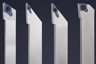
Types of Cutting Tools
There are several types of cutting tools used in lathe operations, including:
- Turning tools: These are employed to remove material from the outer diameter of a workpiece, generating a cylindrical shape.
- Facing tools: Used for cutting material at the end of a workpiece to create a flat surface.
- Boring tools: Essential for enlarging existing holes in a workpiece.
- Cutting-off tools: Designed for parting or separating a portion of the workpiece from the parent material.
Geometry of Tool Angles
The geometry of tool angles plays an essential role in determining the performance and lifespan of a cutting tool. Some critical angles to consider are:
- Rake angle: This angle influences chip formation, cutting force, and temperature generation. A positive rake angle can reduce the cutting force and make chip formation easier, while a negative rake angle can provide a stronger cutting edge, suitable for harder materials.
- Clearance angle: Clearance angles are essential to prevent rubbing between the workpiece and the tool. Insufficient clearance may result in increased wear and heat generation.
- Lead angle: The lead angle is the angle between the cutting edge and the workpiece surface. It affects the direction of forces, chip thickness, and the contact length between the tool and the workpiece. A larger lead angle can result in a thinner chip, reducing cutting forces, but can also compromise surface finish quality.
The selection of tool angles will depend on factors such as the material being cut, the type of lathe operation performed, and the desired outcome for the workpiece. By understanding these basics, one can make well-informed decisions to optimize the lathe cutting process.
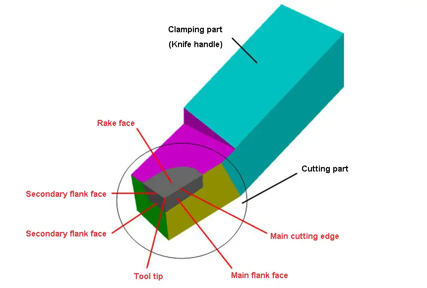
Composition of Lathe Tool Cutting Part
The cutting part of a lathe tool consists of the rake face, main flank face, secondary flank face, main cutting edge, secondary cutting edge, and tool tip.
- Rake face: The surface through which chips flow on the tool.
- Main flank face: The surface on the tool that interacts with and opposes the machined surface on the workpiece.
- Secondary flank face: The surface on the tool that interacts with and opposes the machined surface on the workpiece.
- Main cutting edge: The intersection line between the rake face of the tool and the main flank.
- Secondary cutting edge: The intersection line between the rake face of the tool and the secondary flank.
- Tool tip: The intersection of the main cutting edge and the secondary cutting edge. The tool tip can either be a small curve or a straight line, referred to as the rounding tool tip or the chamfering tool tip.
Auxiliary Plane for Measuring the Lathe Cutting Tool Angle
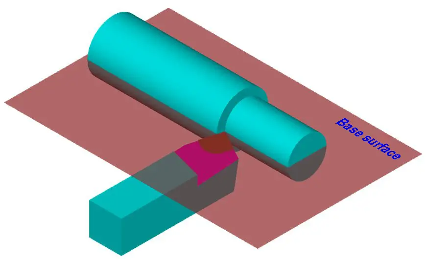
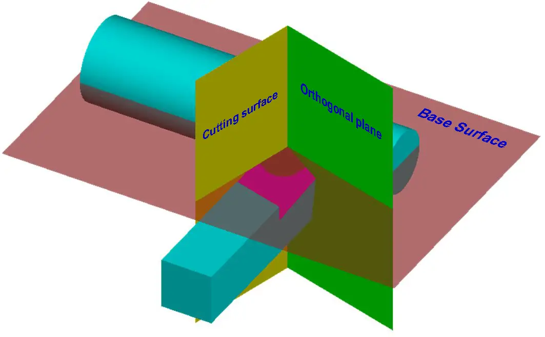
To determine and measure the geometric angle of the lathe tool, three reference planes must be selected. These three reference planes are the cutting plane, the base plane, and the perpendicular plane.
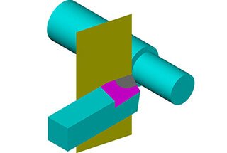
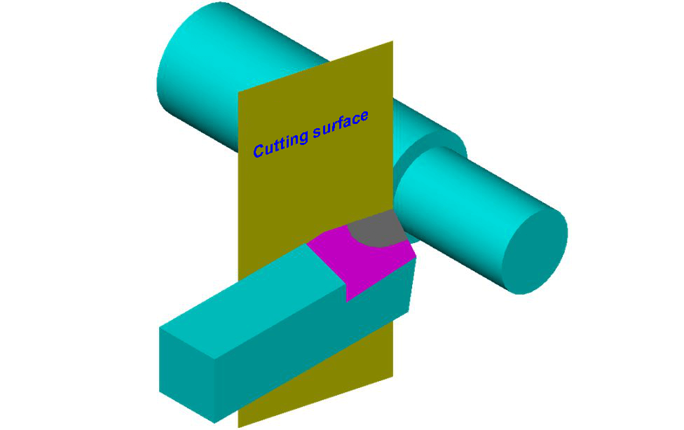
1) Cutting plane
A plane that intersects at a designated point on the main cutting edge and is perpendicular to the base plane of the shank.
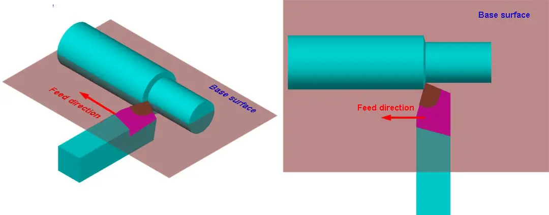
2) Base plane
A plane that passes through a selected point on the main cutting edge and is parallel to the base surface of the shank.
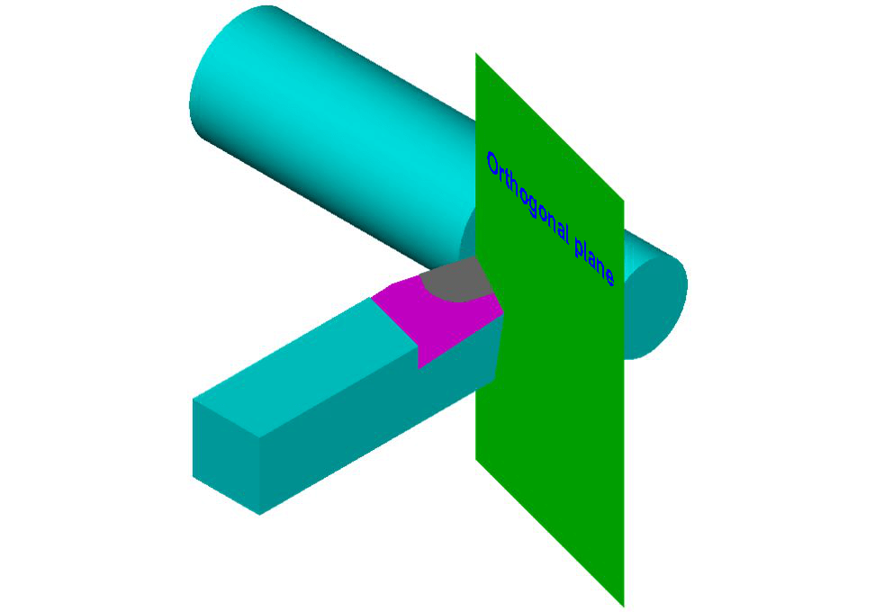
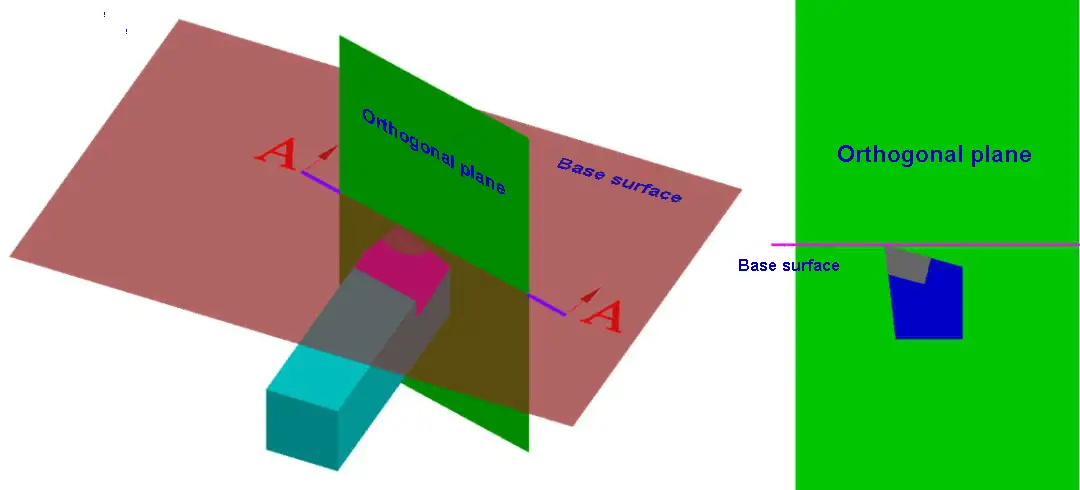
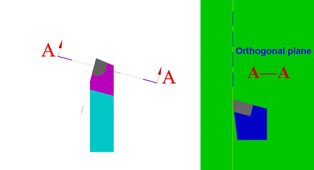
3) Orthogonal plane
A plane that is perpendicular to the cutting plane and perpendicular to the base plane.
It can be seen that these three coordinate planes are perpendicular to each other, forming a space rectangular coordinate system.
Main Geometric Angles and Selection of Lathe Tools
1) Principle of rake angle (γ0 ) selection
The size of the rake angle is a crucial factor in balancing the durability and sharpness of the cutting tool.
When determining the rake angle, the first consideration should be the hardness of the material being cut.
For materials with high hardness, a smaller rake angle is preferred, while for softer materials, a larger angle is appropriate.
Additionally, the type of machining operation also influences the choice of rake angle.
For rough machining, a smaller angle is preferred, while a larger angle is used in finishing operations. A rake angle between -5° and 25° is typically selected.
Typically, the rake angle (γ0) is not predetermined when manufacturing lathe tools. Instead, it is achieved by grinding a chip-discharge groove on the tool.
This groove, also known as a chip-breaking groove, serves to break the chips without winding, control the flow direction of the chips to maintain the accuracy of the machined surface, reduce cutting resistance, and extend the tool’s lifespan.
2) The principle of back angle (α0 ) selection
Firstly, the type of machining should be considered. In finishing machining, the back angle should have a large value, whereas in rough machining it should have a small value.
Secondly, the hardness of the material being processed should be taken into account.
If the material being machined is hard, the main back angle should have a small value to improve the cutter head’s firmness.
On the other hand, if the material is soft, the back angle can have a larger value. The back angle should not be 0° or negative and is generally chosen between 6° and 12°.
3) Principle of cutting edge angle (Kr ) selection
Firstly, the rigidity of the turning process system composed of lathes, fixtures, and tools should be considered.
If the system’s rigidity is good, the entering angle should be a small value, which will increase the service life of the lathe tool, improve heat dissipation conditions, and result in a better surface roughness.
Secondly, the geometry of the workpiece to be processed must be taken into account. When processing steps, the cutting edge angle should be 90°.
For workpieces that are cut in the middle, the cutting edge angle is generally 60°. The cutting edge angle is usually between 30° and 90°, with the most commonly used angles being 45°, 75°, and 90°.
4) The principle of the secondary deflection angle (Kr’) selection
Firstly, the lathe tool, workpiece, and clamp must have sufficient rigidity to reduce the secondary deflection angle, otherwise, a larger value should be taken.
Secondly, consider the nature of the processing.
In finishing machining, the secondary deflection angle should be 10° to 15°, while it should be around 5° for rough machining.
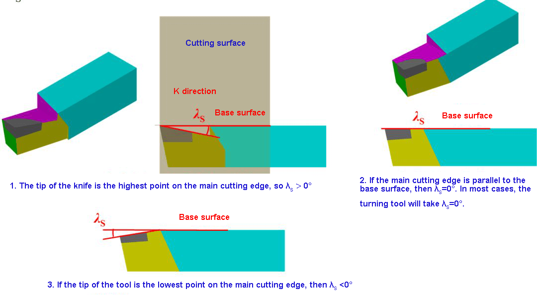
5) The principle of inclination angle (λS) selection
It mainly depends on the nature of the machining process. During rough machining, the workpiece has a significant impact on the lathe tool.
In finishing machining, when λS is less than or equal to 0°, the impact force of the workpiece on the lathe tool is minimal.
When λS is greater than or equal to 0°, a value of 0° is usually taken. The inclination angle is typically selected between -10° and 5°.
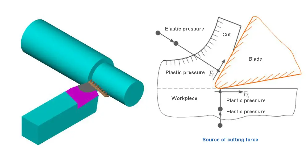
What is the specific impact of lathe tool angles on cutting forces and cutting surface quality?
The influence of lathe tool angles on cutting forces and the quality of the cutting surface is mainly reflected in the following aspects:
Rake Angle: The size of the rake angle directly affects the sharpness of the cutting edge and the cutting force. An increased rake angle can enhance the sharpness of the cutting edge, thereby reducing the cutting force and making the cut more effortless. Simultaneously, a larger rake angle helps improve chip evacuation, reduces cutting deformation, and enhances the quality of the machined surface. However, when the rake angle is too large, the strength of the cutting edge decreases, causing the tool tip to wear faster and the cutting force to increase.
Clearance Angle: The clearance angle is the angle between the cutting face and the line perpendicular to the tool axis. It influences the strength of the cutting edge and chip evacuation. An appropriate clearance angle can enhance the tool’s durability and chip removal efficiency, but an overly large clearance angle may increase the cutting force.
Lead Angle: The lead angle affects the shape of the chip and the direction of the cutting force. Different lead angles are suitable for different machining requirements, such as rough or finish machining. For instance, in rough face milling, a lead angle of 60° to 75° can significantly reduce the radial cutting force, improving vibration resistance and cutting stability.
Tip Chamfer Angle: A larger tip chamfer angle can reduce cutting forces and cutting temperature while enhancing the cutting edge’s life and surface quality. However, if the chamfer angle is too large, it may reduce the cutting edge’s entry angle. The chips can easily block the gap between the tool and the workpiece, affecting the machining results.
What are the best selection criteria for the back angle in different material processing?
The best selection criteria for the back angle in different material processing primarily depend on the properties of the workpiece material (such as hardness, plasticity, toughness, etc.) and the specific requirements of the machining process (such as rough machining or fine machining). Here are the best selection criteria I’ve summarized from my research:
When machining plastic materials, a larger back angle should be chosen. This is because plastic materials tend to deform and stick to the tool. A larger back angle helps reduce friction between the tool and the workpiece, thus improving machining efficiency and surface quality.
When machining brittle or hard materials, a smaller back angle should be chosen. This is because brittle and hard materials are more prone to crack. A smaller back angle can increase the strength of the cutting edge and prevent breakage during the machining process.
During fine machining, due to the smaller cutting thickness, a larger back angle should be chosen to ensure the quality of the machined surface. This makes the tool sharper, reduces wear, and improves machining accuracy.
When machining materials that are prone to forming hardened layers, a larger back angle should also be chosen. This helps prevent the formation of hardened layers and maintain the sharpness of the tool.
For specific materials, such as titanium alloys that have higher plasticity and toughness, a larger back angle should also be considered during machining to reduce the difficulty of machining and improve machining efficiency.
How is the influence of the primary and secondary relief angles on the surface roughness of the machined surface quantified?
The influence of the primary and secondary relief angles on the roughness of the machined surface can be quantified in several ways:
Impact of the primary relief angle: The primary relief angle (KAPR) is the angle between the main cutting edge of the tool and the surface of the workpiece. It affects chip thickness, cutting force, and tool life. As the primary relief angle decreases, chip thickness reduces. This thinning effect of the chips distributes the machined material over a larger part of the cutting edge, which may affect surface roughness.
Impact of the secondary relief angle: The secondary relief angle mainly affects the roughness and quality of the machined surface. A smaller secondary relief angle can reduce surface roughness because it can increase the strength of the tool tip, reduce vibrations, and polish the machined surface.
However, reducing the secondary relief angle can easily cause vibrations, so it needs to be determined based on the rigidity of the machine tool. Moreover, it is common to reduce the surface roughness value by decreasing the secondary relief angle kr’, although this may cause tool vibration.
Comprehensive consideration: Among the geometric parameters of the tool, the primary relief angle Kr, the secondary relief angle Kr’, and the tool tip radius re have a significant influence on surface roughness. When the primary and secondary relief angles are small, the height of the residual area on the machined surface is also small, thereby reducing surface roughness. This indicates that by adjusting the size of the primary and secondary relief angles, surface roughness can be controlled to a certain extent.
What are the specific case studies on the influence of the tool rake angle on chip evacuation direction and machining quality?
The impact of the tool rake angle on chip evacuation direction and machining quality can be primarily observed in the following aspects:
The positive or negative of the rake angle directly influences the flow direction of the chips. When the rake angle is positive, the chip rotates counterclockwise and elongates, forming an angle at its root with the transitioned surface, causing the chip flow to only extend towards the surface to be processed. This indicates that the design of the rake angle plays a vital role in controlling the flow direction of the chips, especially in situations where it’s necessary to reduce chip contamination on the workpiece surface.
In the oblique cutting process of C45 steel, the rake angle λs significantly affects the minimum uncut chip thickness (hmin) within the range of 0° to 60°. This finding has been confirmed through theoretical analysis and experimental verification. This implies that the rake angle not only influences the chip evacuation direction but also has a direct impact on the material removal rate during the machining process.
During angle cutting, the chip flows out of the cutting edge in an inclined direction and produces a lateral bend along the front tool face, forming a spiral chip discharge. This phenomenon is caused by the distribution of frictional forces between the tool and the chip. This further substantiates the significant impact of the rake angle on chip evacuation characteristics.
Adjusting the rake angle can also affect tool durability and the hardening degree of the workpiece. Increasing the rake angle can lead to a drop in the temperature of the rear tool face, thereby reducing back tool face wear. This means that by adjusting the rake angle, tool life can be extended to a certain degree and the surface quality of the workpiece can be improved.
In a high-rigidity system, how do you adjust the angle of the lathe tool according to the geometry and material characteristics of the workpiece?
In high-rigidity systems, adjusting the angle of the lathe tool according to the geometric shape and material characteristics of the workpiece requires initial consideration of the tool’s geometric parameters, including the main lead angle, relief angle, and approach angle.
These parameters significantly impact cutting deformation, cutting force, cutting temperature, and tool wear, thereby affecting cutting efficiency, tool life, workpiece surface quality, and machining cost. For instance, adjusting the tool’s angles, particularly the main lead angle, relief angle, and approach angle, can solve the issue of machine tool vibration and tool chattering.
For different workpiece shapes and materials, selecting the appropriate tool shape is also crucial. For example, an 80-degree diamond-shaped blade is suitable for a wide range of applications from rough machining to fine machining, while a 55-degree or 35-degree diamond-shaped blade is typically used for contour machining. Moreover, the geometric shape of the tool should also consider factors such as the geometric shape of the workpiece, its material, and surface quality requirements.
In practical operations, attention should also be paid to the size of the residual area left on the machined surface when the tool makes a feeding motion relative to the workpiece. Reducing the main lead angle, the relief angle, and increasing the tool tip radius can all decrease the height of the residual area. This implies that when adjusting the tool angle, one must consider not only the geometric parameters of the tool but also how these parameters impact physical phenomena during the cutting process, such as cutting force and cutting efficiency.
Adjusting the angle of the lathe tool according to the geometric shape and material characteristics of the workpiece requires a comprehensive consideration of the tool’s geometric parameters (such as the main lead angle, relief angle, and approach angle), selecting the appropriate tool shape, and considering the interaction between the tool and the workpiece as well as the physical phenomena during the cutting process. Such adjustments can help improve machining efficiency, prolong tool life, and ensure the quality of workpiece machining.