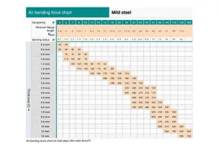
Air Bending Force Chart (Amada)
In this blog post, we'll explore the fascinating world of air bending and the force charts that make it possible. Join us as we delve into the science behind this…
Have you ever wondered how to accurately calculate the bending force required for sheet metal fabrication? In this insightful blog post, we’ll explore the intricacies of bending force calculation, drawing from the expertise of seasoned mechanical engineers. Discover the key factors that influence bending force and learn how to apply proven formulas to optimize your metal forming processes. Get ready to elevate your sheet metal bending knowledge to new heights!

At present, the formulas for calculating bending force that are widely used have been adopted from foreign sources without any information about their origin or scope of application.
This article presents a systematic analysis of the derivation process of the formula for calculating bending force, as well as the required parameters.
Furthermore, a new approach for calculating bending force is introduced to broaden its scope of application.
In recent years, the press brake machine has gained widespread use across various industries and has expanded its processing capabilities.
Despite its popularity, there has been a lack of systematic discussion on the calculation of bending force.
Currently, there are approximately two types of bending force calculation formulas recommended by the product manuals of different press brake manufacturers.
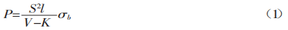
In the formula:
The recommended formula for calculating the bending force by the manufacturer is based on a previously mentioned formula.
Both of these formulas have been taken from various product brochures, however, there is no proof of their accuracy.
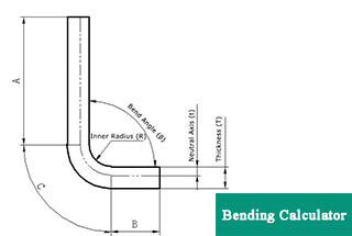
Related calculator: Press Brake Tonnage Calculator
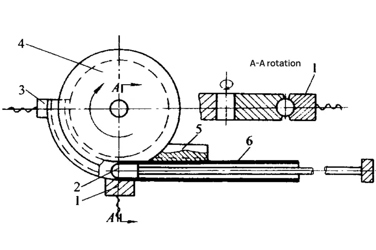
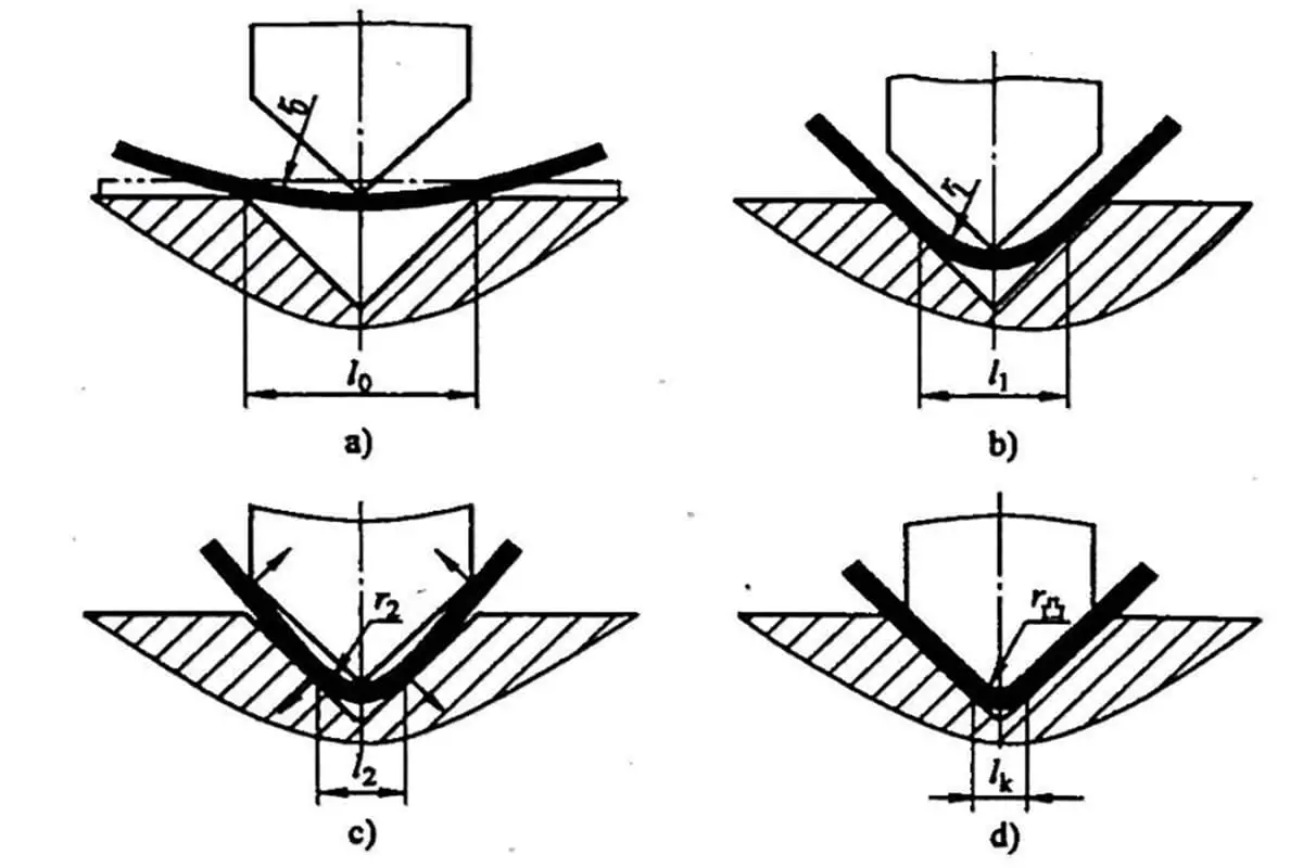
Figure 1 is a schematic representation of the bending process of a sheet.
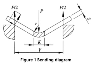
The calculation of the bending force and its parameters are explained as follows:
The recommended width of the lower die opening (V) for free bending is 8 to 10 times the sheet thickness (S), with a width-to-thickness ratio of V/S = 9.
Press brake manufacturers provide the values of the die width (V) and the inner radius (r) of the bent workpiece in their bending force parameter table. The radius-to-width ratio is usually r = (0.16 to 0.17) V, and in this case, the value of 0.16 is used.
During the bending process, the material in the deformation zone undergoes significant plastic deformation, causing it to bend around the centerline.
In some instances, small cracks may appear on the outer surface of the curved area.
The stress in the deformation zone, except near the central layer, is close to the material’s tensile strength, with the upper part of the neutral layer being compressed and the lower part being in tension.
Figure 2 illustrates the cross-section and corresponding stress diagram in the deformation zone.
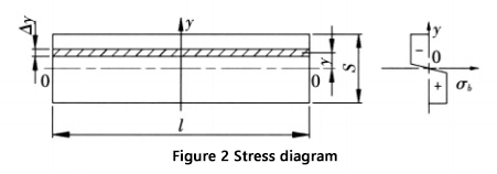
The bending moment at the section of the deformation zone is:
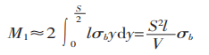
The bending moment produced by the bending force in the deformation zone is depicted in Figure 1.
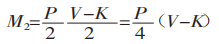
From M1 = M2, we get:
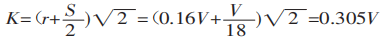
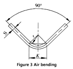
When bending a sheet with a universal mold on a bending machine, as shown in Figure 3, most sheets are bent to 90°. In this case, K is:
By substituting K into equation (1), we obtain:
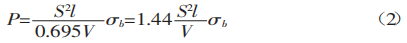
The tensile strength of ordinary materials, σb, is 450 N/mm². This value can be used in formula (2) to calculate the result.
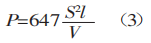
The formula for calculating the bending force obtained here is in agreement with the information provided in foreign brochures.
The variables in the formula are:
As can be seen from the derivation process, when using formulas (2) or (3) to calculate the bending force, it is important to ensure that two additional conditions are met: the ratio of width to thickness (V/S) must be equal to 9, and the ratio of radius to width must be equal to 0.16.
If these conditions are not satisfied, significant errors may result.
The calculation of bending force can be complicated when it is not possible to meet the two additional requirements (width-to-thickness ratio V/S = 9 and radius-to-width ratio = 0.16) due to design or process limitations.
In such situations, it is advisable to follow these steps:
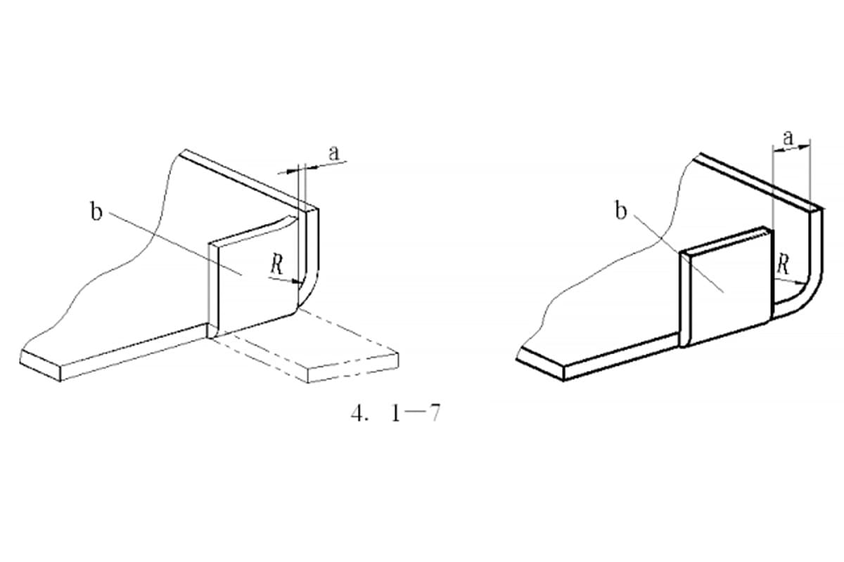
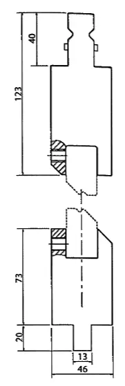
These steps will provide a more precise and dependable result compared to using the commonly used formula. An example to illustrate this process is shown in Figure 4.
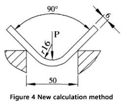
Given: Sheet thickness (S) = 6mm, Sheet length (l) = 4m, Bending radius (r) = 16mm, Lower die opening width (V) = 50mm, and Material tensile strength (σb) = 450N/mm².
Question: How can we calculate the bending force required for air bending?
Here are the steps:
First, calculate the ratio of width to thickness and the ratio of radius to width:
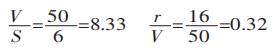
Then calculate the projected width of the deformation area:
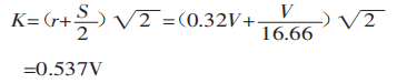
Finally, use formula (1) to calculate the bending force:
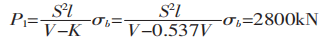
If the usually recommended formula is used to calculate the bending force:
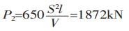
It can be inferred from P1/P2 = 1.5 that the difference between P1 and P2 is 1.5 times.
The reason for this discrepancy is because in this example, the bending radius is relatively large, which results in an increased deformed area and therefore requires a greater bending force.
The ratio of radius to width in this example is 0.32, which surpasses the previously mentioned criteria.
Using the standard formula to calculate the bending force is not suitable for this scenario. The advantages of using the new method for calculation can be observed in this example.
Additionally, there is an online calculator available to calculate the bending force using the new method.
Tensile Strength Table
| Material | Tensile strength | ||
|---|---|---|---|
| American | European | China | N/mm² |
| 6061 Aluminum | Alu50 | LD30 | 290 |
| 5052 Aluminum | Alu35 | LF2 | 303 |
| 1010 Mild steel | DC01 | 10/10F | 366 |
| A 536 -80 G 60-40-18 | GGG-40 | QT400-18 | 400 |
| A 351 G CF 8 | G-X 6CrNi 18 9 | Q235 | 450 |
| A 572 G50 | S 355 MC | Q345 | 550 |
| 304 Stainless | Inox V2A | 0Cr18Ni9 | 586 |
| 316 Stainless | Inox V4A | 0Cr17Ni12Mo2 | 600 |
| 4140 Low alloy | 42 CrMo 4 | 42CrMo | 1000 |
The formulas for calculating coining parameters are different from air bending.

1. Width of the die vee:
V = sheet metal thickness × 5
2. The internal radius is determined by the punch tip, which should be chosen in accordance with the following formula:
Radius = sheet metal thickness × 0.43.
3. Force required for coining:
F(kn/m)=Thickness2×1.65×Tensile Strength (N/mm2)×4.5/Die Vee Width
4. The formula for calculating the minimum internal edge remains the same:
Minimum internal edge = Die vee × 0.67

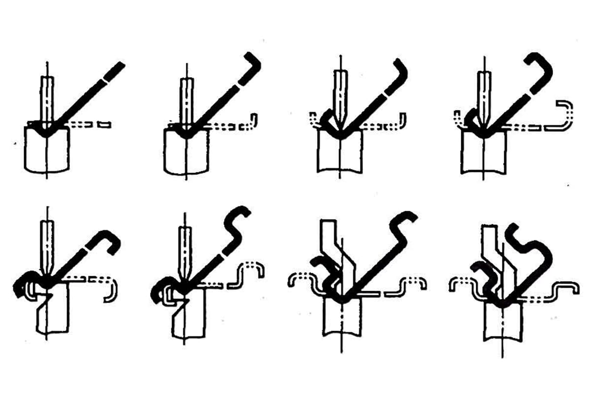
Some tools need a particular force to yield the sheet metal and to manage springback in order to obtain the profile re-quired.
As an example we will consider joggle tools, which make two bends at once with a short distance between bend and counterbend.
As these tools make two bends at once, springback has to be canceled completely by coining.
The equation to calculate the necessary force is:

Joggle tools usually consist of an insert holder into which the joggle tools chosen in accordance with the joggle and the angle required are secured with grub- screws.
It is important to ask for technical advice from the manufacturer before purchasing, because these systems can only bend thin sheet metal, a maximum 2mm, but the maximum thickness will depend on the type of insert and it could be less than 2mm.
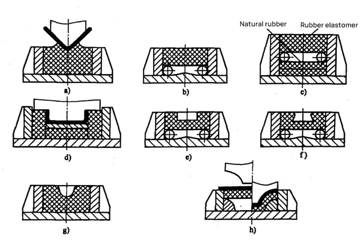
The formulas and steps provided for calculating the bending force are suitable not only for angular bending of a sheet, but also for arc-shaped bending (which technically should be referred to as angle bending with a large bending radius).
It is crucial to keep in mind that forming an arc shape requires a unique mold design.
When projecting the deformation area, the calculation must be based on the process parameters established during the process, which cannot be determined through a single formula.
At a specific iron tower factory, we successfully bent a cylinder with a wall thickness of 12mm, a diameter of 800mm, and a length of 16m using a 28000kN press brake machine and a circular mold.
The method outlined in this article was utilized to determine the bending force and produced satisfactory results when designing a mold for an arc shape.
Further reading:

As the founder of MachineMFG, I have dedicated over a decade of my career to the metalworking industry. My extensive experience has allowed me to become an expert in the fields of sheet metal fabrication, machining, mechanical engineering, and machine tools for metals. I am constantly thinking, reading, and writing about these subjects, constantly striving to stay at the forefront of my field. Let my knowledge and expertise be an asset to your business.