This manual is applicable to maintenance personnel who do not have dedicated debugging instruments and equipment. Maintenance personnel use digital or pointer multimeters for measurement and repair. Analyze the cause of the fault through the fault phenomenon and measurement data, determine which components are damaged, and find a solution.
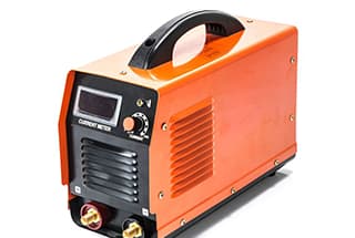
After the welder fails, first remove the machine casing and check whether there is any scorching or burning inside.
Focus on the following parts:
(1) Upper board section: MOSFET, Control Module, Drive Module, Auxiliary Power Supply
(2) Bottom board section: Electrolytic capacitor, High-voltage silicon grain, Thermistor, Varistor. If scorching or burning is discovered, the board can be replaced directly.
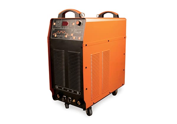
Chapter 1 – Manual Arc Welding Series
Troubleshooting
Switch power indicator does not light up, fan does not rotate, no welding output
1. Confirm that the power switch is closed.
2. Confirm that the input cable is connected to a power source with electricity.
Power indicator lights up, fan does not rotate, no welding output
1. It may be due to the input being connected to a 380V power supply, causing the overvoltage protection circuit to start. Switch to a 220V power supply and restart the machine.
2. Unstable 220V power (input wire too thin or too long) or input wires are overlapped on the power grid, causing the overvoltage protection circuit to start. Increase the wire diameter of the input wires and tighten the connection points. This phenomenon can be resolved by turning off the machine for 5-10 minutes before restarting it.
3. Continuous opening and closing of the power switch in a short period of time causes the overvoltage protection circuit to start. Turn off the machine for 5-10 minutes before restarting it to restore normal operation.
4. The wire between the power switch and the power board is loose. Re-tighten it.
5. The 24V relay on the power board is not energized or damaged. Check the 24V power supply and relay. You can replace the relay with another relay of the same model.
Fan rotates, welding output current is unstable or not controlled by the potentiometer, current is sometimes large and sometimes small
1. The 1K potentiometer may have quality problems. It should be replaced.
2. Poor contact in various connection points, especially connectors, needs to be checked.
Fan rotates, abnormal indicator does not light up, no welding output
1. Check whether various internal connection lines are in poor contact.
2. There is a break or poor contact at the output terminal connection point.
3. Use an instrument to measure the voltage from the power board to the MOS board (VH-07 connector), which should be around DC 308V.
(1) Whether the silicon bridge is broken or the connector is in poor contact.
(2) Replace individual leaking electrolytic capacitors (around 470UF/450V) among the four large ones on the power board.
4. If the green indicator of the auxiliary power supply on the MOS board does not light up, please contact the dealer or the company.
5. For control circuit problems, please contact the dealer or the company.
Fan rotates, abnormal indicator lights up, no welding output
1. It may be overcurrent protection. Turn off the machine and wait for the abnormal indicator to turn off before restarting to restore normal operation.
2. It may be overheating protection. Wait 5-10 minutes for the machine to naturally recover.
3. It may be an inverter circuit failure: unplug the power plug of the main transformer on the MOS board (near the fan VH-07) and restart the machine:
(1) If the abnormal indicator is still on, individual MOSFETs on the MOS board may be damaged. Find and replace them with the same type of MOSFETs.
(2) If the abnormal indicator does not light up.
A. The intermediate transformer may be damaged. Use a bridge to measure the primary inductance and Q value of the main transformer. The primary is in parallel, L=12.2-2.0mH, Q>40. If the inductance and Q values are both too small, they should be replaced.
B. Some rectifying tubes in the transformer secondary may have breakdown. Look for and replace the same type of rectifying tubes.
4. It may be a feedback circuit failure.
5. Common troubleshooting for ARC 250, ARC 315, ARC 400, ARC 400B, ARC 500
The meter head does not display, the fan does not rotate, and there is no welding output
1. Confirm that the air switch is closed.
2. The input cable is connected to a power source with electricity.
3. Thermistors (4) are damaged (24V relay normally open point does not close or contact is poor).
4. Power board (bottom board failure, no output DC 537V voltage):
(1) Silicon bridge is broken, and the connector of the silicon bridge is in poor contact.
(2) The power board has scorching or burning areas.
(3) Check the connection line from the air switch to the power board and the connection line from the power board to the inverter board (MOS board).
5. The auxiliary power supply part on the control board fails. (Contact the dealer or manufacturer)
The meter head displays normally, the fan rotates normally, and there is no welding output
1. Check whether various internal connection lines are in poor contact.
2. There is a break or poor contact at the output terminal connection point.
3. Inverter circuit failure (abnormal indicator lights up)
Please unplug the power supply line of one of the inverter boards (near the front panel VH-07 connector) and the power supply line of the transformer (near the fan VH-07 connector) and restart the machine:
If the abnormal indicator does not light up, the fault is on this inverter, otherwise, the fault is on the other inverter. Next, turn off the power, plug in the power supply line of the faulty inverter (do not plug in the power supply line of the main transformer), and restart the machine:
1) If the abnormal indicator does not light up, the fault is on the intermediate board;
a. The intermediate transformer may be damaged. Use a bridge to measure the primary inductance and Q value of the main transformer, and measure each transformer separately. If the inductance or Q value is very small, replace it.
b. Some rectifying tubes in the intermediate board may be damaged. Replace them.
2) If the abnormal indicator lights up, the fault is on the MOS board, and some of the inverter MOSFETs are damaged. Replace them with the same type of MOSFETs.
4. Feedback circuit failure (abnormal indicator lights up). Contact the dealer or manufacturer. Large welding spatter, unreasonable output polarity connection, exchange the output electrode polarity.
Chapter 2 – TIG Welding Series
1. The power switch is turned on, but the green light does not turn on, the fan does not rotate, and there is no response inside the machine when the welding gun switch is pressed.
• Cause Analysis:
1. External power supply is abnormal.
2. The power cable is broken or the connector is poor.
3. The power switch is damaged.
• Troubleshooting:
1. Check the external 220V/AC voltage.
2. Check the connectors.
3. Replace the power switch.
2. The power switch is turned on, the green light does not turn on, the fan rotates, and there is no response inside the machine when the welding gun switch is pressed.
• Cause Analysis:
1. The power switch to the bottom board connector is not plugged in properly.
2. The auxiliary power supply on the upper board is damaged and there is no DC 24V output.
• Troubleshooting:
1. Check the connectors.
2. Repair or replace the auxiliary power supply.
3. The green light turns on after turning on the machine, the fan rotates, but there is no response when pressing the welding gun switch.
• Cause Analysis:
1. The welding gun switch or control line is loose.
2. Poor contact of the aviation socket or disconnected connection wire.
• Troubleshooting:
Check and replace.
4. After turning on the machine normally, there is gas out when pressing the welding gun switch, but the red light does not turn on and there is no high frequency.
• Cause Analysis:
Firstly, check the output end of the welder, unplug the high-frequency control line, and see if there is a DC 55V no-load voltage. If there is a DC 55V, see if it can arc.
If it can arc, focus on checking the high-frequency arc starting part:
1. Whether the boost transformer connection line from the upper board to the bottom board is loose or the transformer is open circuit.
2. Whether the high-voltage silicon grain and the high-voltage capacitor 102/10KV are breakdown damaged.
3. Whether the high-voltage discharge nozzle is sticky, the gap is too large, or the surface is severely oxidized.
4. Whether the high-frequency arc starter and the connector are loose.
5. Whether the high-frequency control relay is damaged and whether its power supply circuit is normal.
6. Whether the switch with ARC/TIG conversion function is good. If there is no DC 55V output, check whether the inverter circuit works normally:
① Whether the control module has a driving signal output.
② Whether the driving conversion and driving modules work normally.
③ Whether the connection line of the field tube, main transformer and main current is loose.
• Troubleshooting:
1. Check and replace.
2. Check and replace.
3. Adjust or replace.
4. Check and replace.
5. Check and replace.
6. Check and replace.
5. After turning on the machine normally, there is gas out when pressing the welding gun switch, but the red light turns on.
• Cause Analysis:
1. Overcurrent protection during operation.
2. Overheat protection during operation.
3. It may be a fault in the inverter circuit and arc-starting part. (After shutting down, unplug the power plug of the arc-starting transformer on the MOS board (near the fan VH-03), and turn on the machine by pressing the welding gun switch.
a. If the red light does not turn on, it is a short circuit of the arc-starting transformer or it may be boost arc starting and the diode breakdown.
b. If the red light turns on, there is a problem with the inverter circuit. Shut down and unplug the power plug of the intermediate transformer (near the fan VH-07), and turn on the machine by pressing the welding gun switch.
c. If the red light turns on, some of the MOSFETs on the inverter board are damaged, and at the same time, check whether there are any component damage in the driving module.
d. If the red light does not turn on, it is a short circuit of the intermediate transformer or rectifier tube. The inductance and Q value of the transformer can be detected using a bridge. C = 0.9-1.6mH, Q> 35, and each rectifying tube should be checked and excluded one by one.
• Troubleshooting:
1. Turn off the machine for 5 minutes and then turn it back on.
2. Stop working for 5 minutes.
a. Replace it; b. Check and replace; c. Check and replace; d. Replace if it is too small.
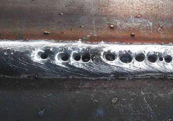
6. The machine turns on normally, can arc, but the welding point becomes black.
• Cause Analysis:
1. Check whether the solenoid valve and its air pipe are blocked by foreign objects.
2. The solenoid valve is damaged.
3. The power supply control circuit of the solenoid valve is damaged.
4. Remove the welding gun, press the welding gun switch, if there is gas out, it means the welding gun is damaged or leaking gas.
5. Poor current-carrying capacity of the welding gun cable, causing arc scattering or deviation.
6. Poor quality tungsten electrode or impure argon gas.
• Troubleshooting:
1. Clean.
2. Replace.
3. Check and replace.
4. Replace.
5. Replace.
6. Replace.
7. The welding current is unstable and not controllable, sometimes large and sometimes small.
• Cause Analysis:
1. Poor or damaged potentiometer contact.
2. Leakage or damage to the bottom board filtering capacitor.
3. Input cable or output cable is too long or thin, causing unstable current.
4. Poor contact or loose connector.
• Troubleshooting:
1. Check and replace.
2. Check and replace.
3. Increase the cross-sectional area of the conductor.
4. Check and replace.
8. The machine trips when turned on.
• Cause Analysis:
1. Rectifier silicon bridge short circuit.
2. Power cord loose and short circuit.
• Troubleshooting:
1. Replace.
2. Plug in securely.
9. When pressing the welding gun switch, the gas valve closes immediately without delay, and the sealing wave is slow.
• Cause Analysis:
The IN4004 diode for the power supply of the gas valve control relay is short-circuited.
• Troubleshooting:
Check and replace.
10. There is a high-frequency discharge sound when pressing the welding gun switch, but there is no current output.
• Cause Analysis:
1. Poor or loose contact of the welding gun ground wire.
2. The output terminal of the ground wire and the air-electric joint are loose or the connection to the intermediate board is loose.
• Troubleshooting:
1. Check and replace.
2. Check and replace.
11. Arc ignition is not good.
• Cause Analysis:
1. The gap between the discharge nozzle is too large or too small, or the surface is oxidized.
2. The capacity of the high-voltage output capacitor is low, and there is a short circuit in the high voltage.
3. Dust in the arc starter causes inter-turn leakage.
4. Poor quality argon gas or tungsten electrode.
5. The welding gun has a loose connection.
• Troubleshooting:
1. Clean and adjust.
2. Check and replace.
3. Check and replace.
4. Check and replace.
5. Check and replace.
12. When turning on the machine, the red light turns on immediately after starting work.
• Cause Analysis:
1. The negative feedback circuit is open.
2. Poor contact of the main current transmission circuit or power device causes overcurrent protection.
• Troubleshooting:
1. Check the connection.
2. Check and replace.
13. High frequency occurs when turning on the machine.
• Cause Analysis:
1. The hand switch control optocoupler PC817 (or transistor 8050) is damaged.
2. Short circuit of the welding gun switch or control line.
• Troubleshooting:
1. Check and replace.
2. Check.
14. High frequency occurs continuously during welding.
• Cause Analysis:
1. The high-frequency control relay is damaged.
2. There is peak interference in the output voltage.
3. High-frequency self-locking.
• Troubleshooting:
1. Replace.
2. Tighten the feedback and control line.
3. Increase the absorption of the high-frequency transformer and increase the capacitance at the coil end of the high-frequency relay.