Welding Symbols Explained: Complete List with Diagrams
Welding symbols may seem like a foreign language, but mastering them is crucial for effective communication in the world of mechanical engineering. In this blog post, a seasoned mechanical engineer will demystify these intricate symbols, providing you with the knowledge to interpret and apply them confidently in your projects. Get ready to unlock the secrets of welding symbols and elevate your engineering skills to new heights!
This standard outlines the method of presenting welding symbols. It is applicable to both metal fusion welding and resistance welding.
2. Normative References
GB/T 5185: Designation of Metal Welding and Brazing Methods in Drawings
GB/T 12212: Technical Drawings – Dimension, Proportions, and Simplified Representation of Welding Symbols
3. Basic Requirements
3.1 Clear Indication of Weld Type
The welding symbol should clearly indicate the type of weld to be made and should not include excessive notes. The representation of the weld can be through the use of a weld graphic method or a weld symbol annotation method. The method of weld symbol marking is generally preferred, but if it’s unclear or if the graphical method is simpler, it can be used instead.
3.2 Components of Welding Symbols
The welding symbol consists of a basic symbol and leader, and additional symbols such as an auxiliary symbol, supplementary symbol, and weld size symbol can be added if needed. The scale, size, and representation method of the graphic symbols should comply with GB/T 12212. For commonly used graphic methods in GB/T 12212, see Appendix C (normative appendix).
3.3 Indication of Weld Size and Process
When professional standards specify the weld size and process, these should be indicated in the welding symbol. The welding method marked on the drawing should be in accordance with Appendix B (normative appendix). Any post-welding processing such as spading, grinding, or cutting should be indicated in the technical requirements.
I. Basic Forms of Weld Seam Overlap
1. Butt Joint
2. Overlap
3. Right Angle Connection
4. T-shaped Joint
5. Bevel Joint:
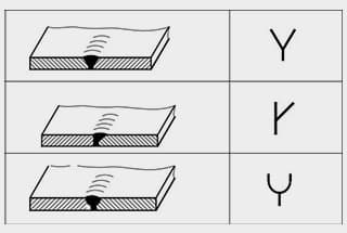
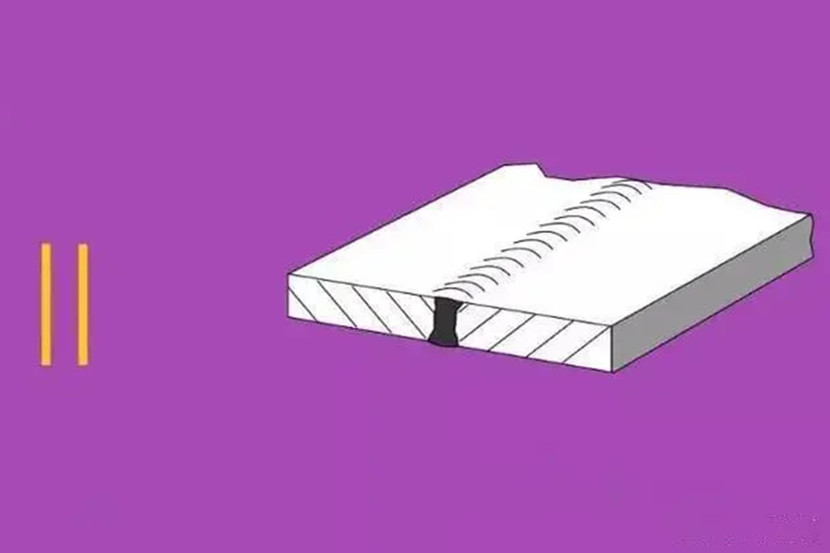
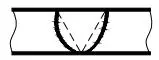
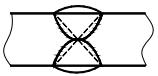
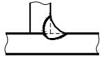
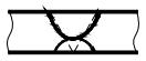
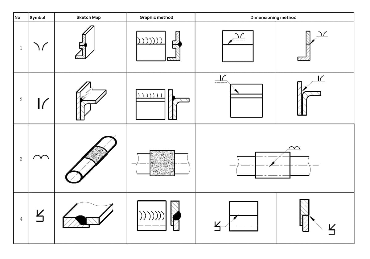
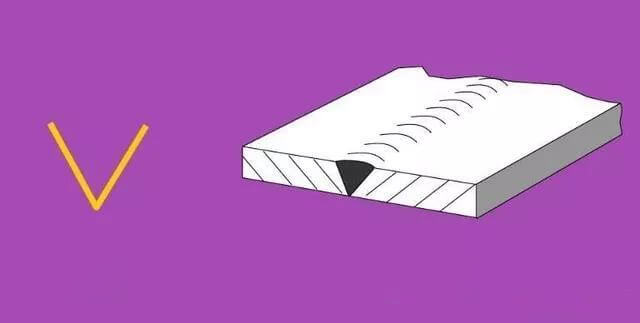
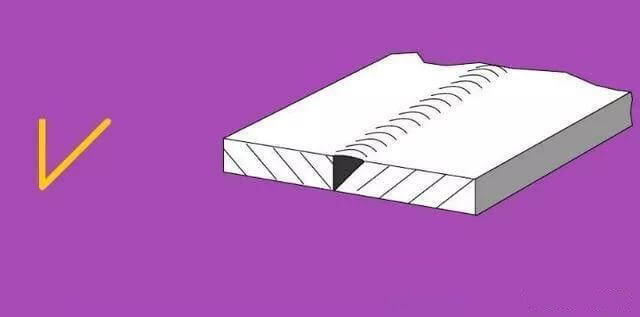
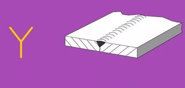
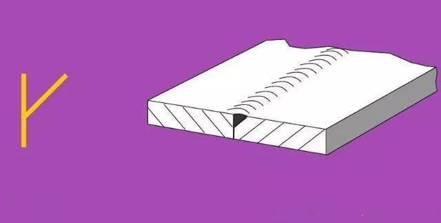
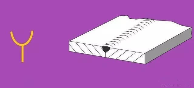
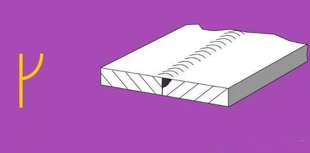
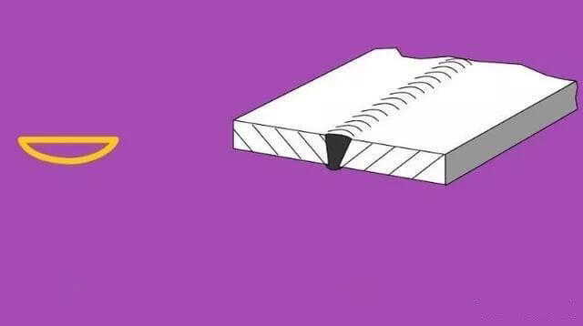
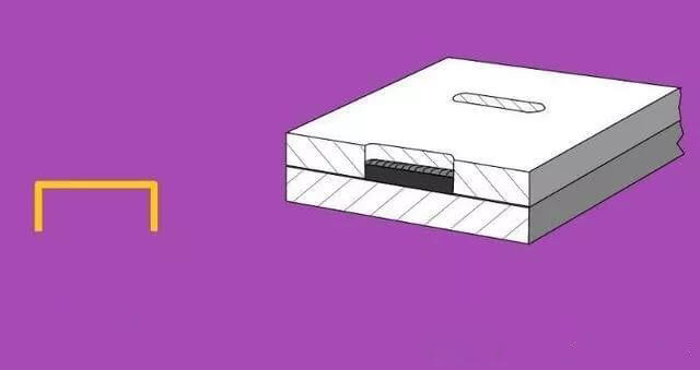
II. Basic Fracture Shapes of Weld Seams
No.
Schematic Diagram
Bevel Form
Welding symbols
1
I-shaped Groove
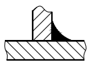
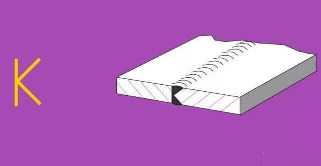
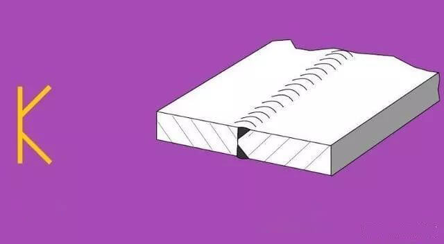
2
K-shaped Groove
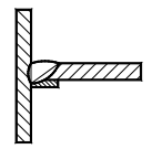
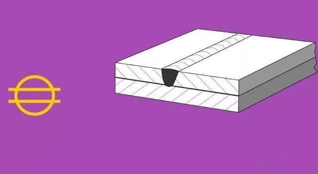
3
V-shaped Groove
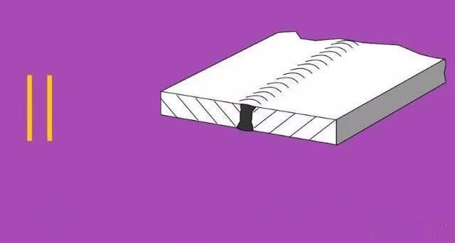
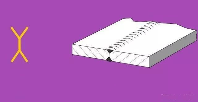
4
X-shaped Groove
5
Y-shaped Gap
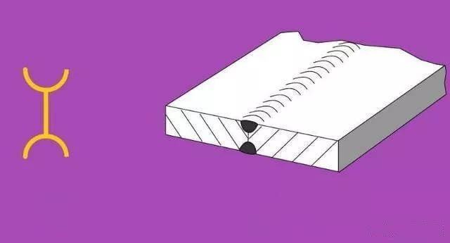
6
X-shaped (with pure edge)
7
Oblique V-shaped Gap
8
Oblique Y-shaped Gap
9
Overlap (three-side weld)
10
U-shaped Gap
11
Single-sided U-shaped Break
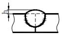
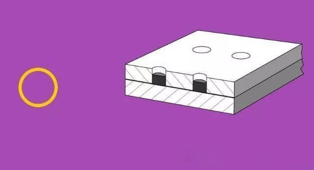
12
Spot Welding
13
Irregular Break
14
Irregular Break
15
Irregular Break
III. Welding Symbols
1. Definition of Welding Symbols
Welding symbols are standardized notations used on engineering drawings to convey detailed information about welding requirements. These symbols indicate the welding methods, weld form, weld size, and other technical details necessary for the fabrication process.
2. Components of Welding Symbols
Welding symbols are composed of several elements, each serving a specific purpose in conveying detailed welding instructions:
(1) Weld Symbols
Basic Symbols: Represent the cross-sectional shape of the weld, such as fillet, groove, or spot welds.
Supplementary Symbols: Indicate additional features of the weld, such as contour (e.g., flat, convex, concave).
Additional Symbols: Provide further details about the weld characteristics, such as finish symbols or field weld symbols.
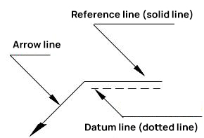
(2) Reference Line
The reference line is a fundamental part of the welding symbol structure, consisting of:
Arrow Line: Points to the location where the weld is to be made.
Reference Line: A horizontal line where weld symbols and dimensions are placed.
(3) Weld Size Symbols
These symbols specify the dimensions of the weld, such as the size of the fillet weld or the depth of the groove.
3. Standard Position of Weld Symbols on Drawings
Basic Annotation Format of Weld Symbols
Standards for welding symbols, such as those provided by the American Welding Society (AWS) or ISO, dictate precise rules for the placement of weld symbols, dimension symbols, and dimension values on the reference line. Adhering to these standards ensures clarity and consistency in welding diagrams.
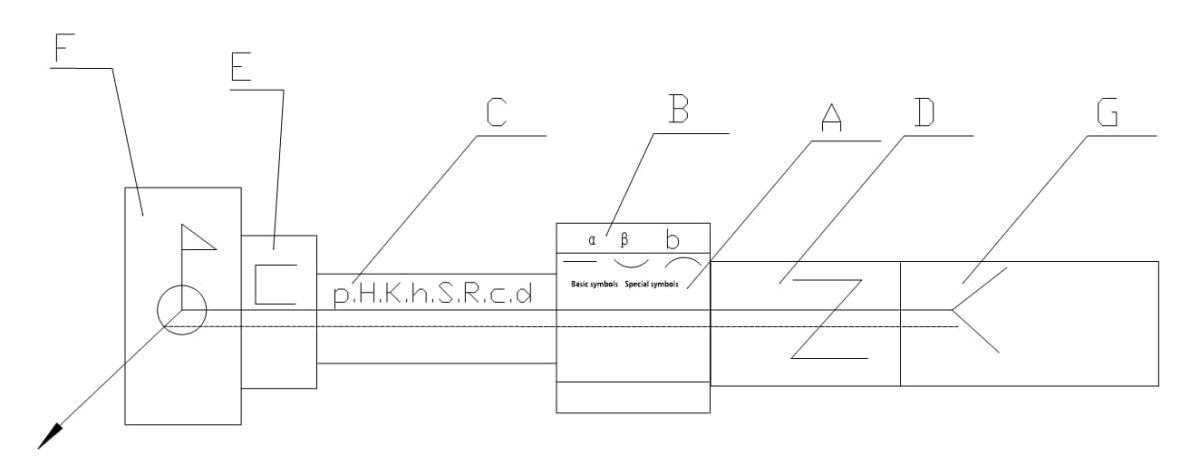
Symbols and numeric values are positioned in seven distinct zones (A~G) relative to the reference line. These zones remain fixed in position regardless of the direction of the arrow line. The zones are defined as follows:
A Zone: Main Functional Area
Content: Basic symbols, special symbols, backing strip symbols, and symbols for plane, convex, and concave in auxiliary symbols.
B Zone: Supplementary Functional Area
Location: Above or below the A Zone.
Content: Groove angle (α), groove surface angle (β), and root gap (b) in the weld size.
C Zone: Left Side of the Basic Symbol
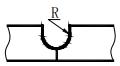
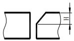
Content: Dimension symbols and values on the cross-section of the weld, such as blunt edge (p), groove depth (H), weld angle size (K), reinforcement (h), effective weld thickness (S), root radius (R), weld width (C), and fusion core diameter (d).
D Zone: Right Side of the Basic Symbol
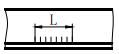
Content: Staggered weld symbols and longitudinal size values of the weld, such as the number of weld sections (n), weld length (l), and weld spacing (e).
E Zone: Three-Side Weld Symbols
Content: Marks the three-side weld symbols in supplementary symbols.
F Zone: Field Weld Symbols
Content: Marks the field weld symbols and surrounding weld symbols in supplementary symbols.
G Zone: Tail Symbols
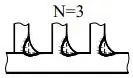
Content: Marks the tail symbols in supplementary symbols. After the tail symbols, additional information such as the number of identical welds (N), welding method code, weld quality, and inspection requirements are noted.
4. Representation Codes of Common Welding Methods in Drawings
Refer to the table below (note: the table is not provided in the query).
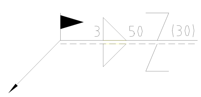
Indication: Weld height is 3, staggered welding, weld seam length is 50, interval is 30, site welding is required.
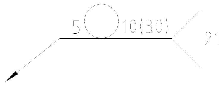
Example 2:
Statement: Spot weld diameter is 5, the number of spot welds is 10, and the interval is 30.
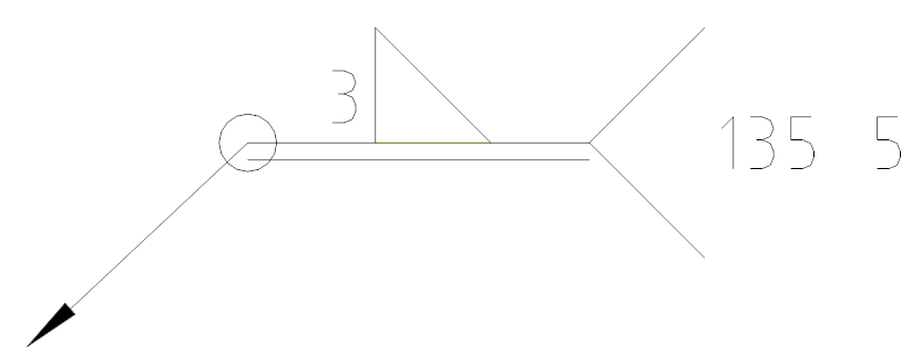
Example 3:
Indication: The weld height is 3, with full welding around. The joint is made using CO2 gas shielded welding, with a total of 5 locations.
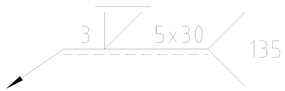
Example 4:
Indication: The weld height is 3, with a bevel V-groove, the weld surface is ground flat, the weld length is 30, in total 5 segments, and the welding is carried out using CO2 gas shielded welding.
6. Basic symbols
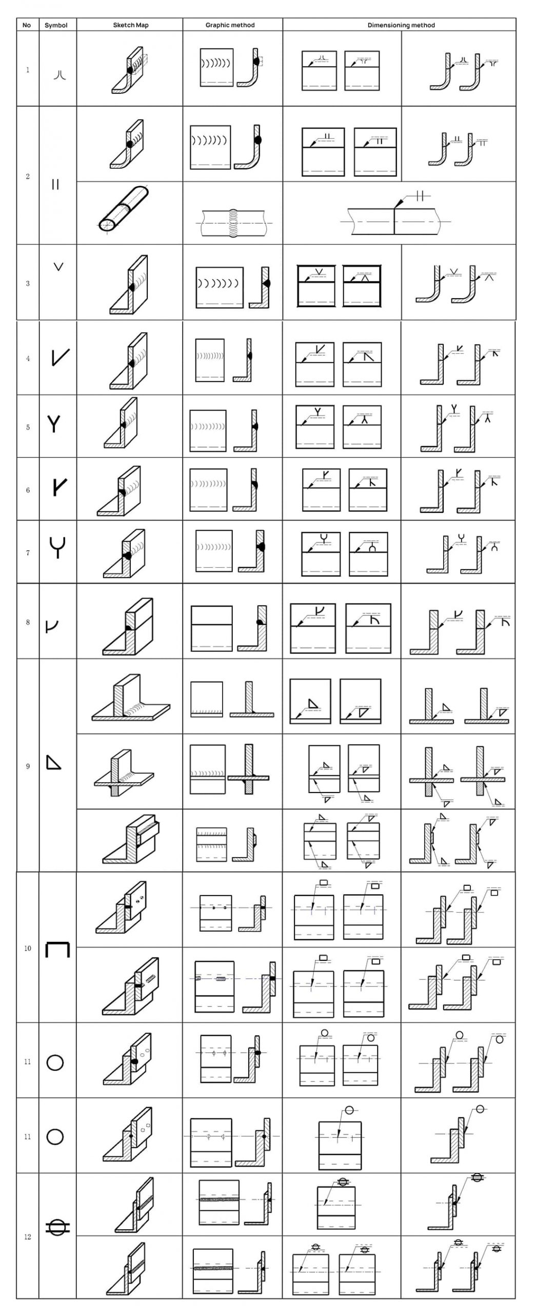
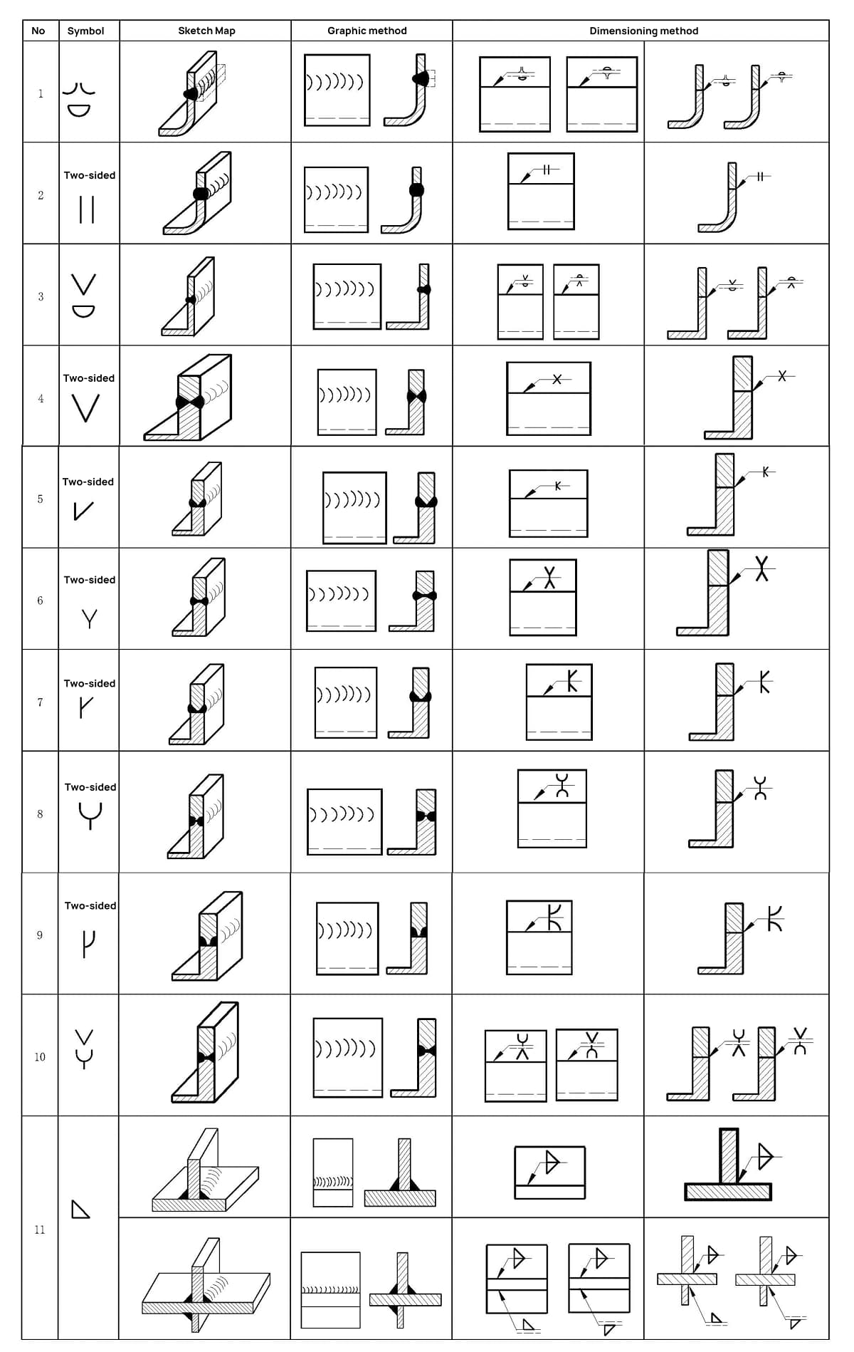
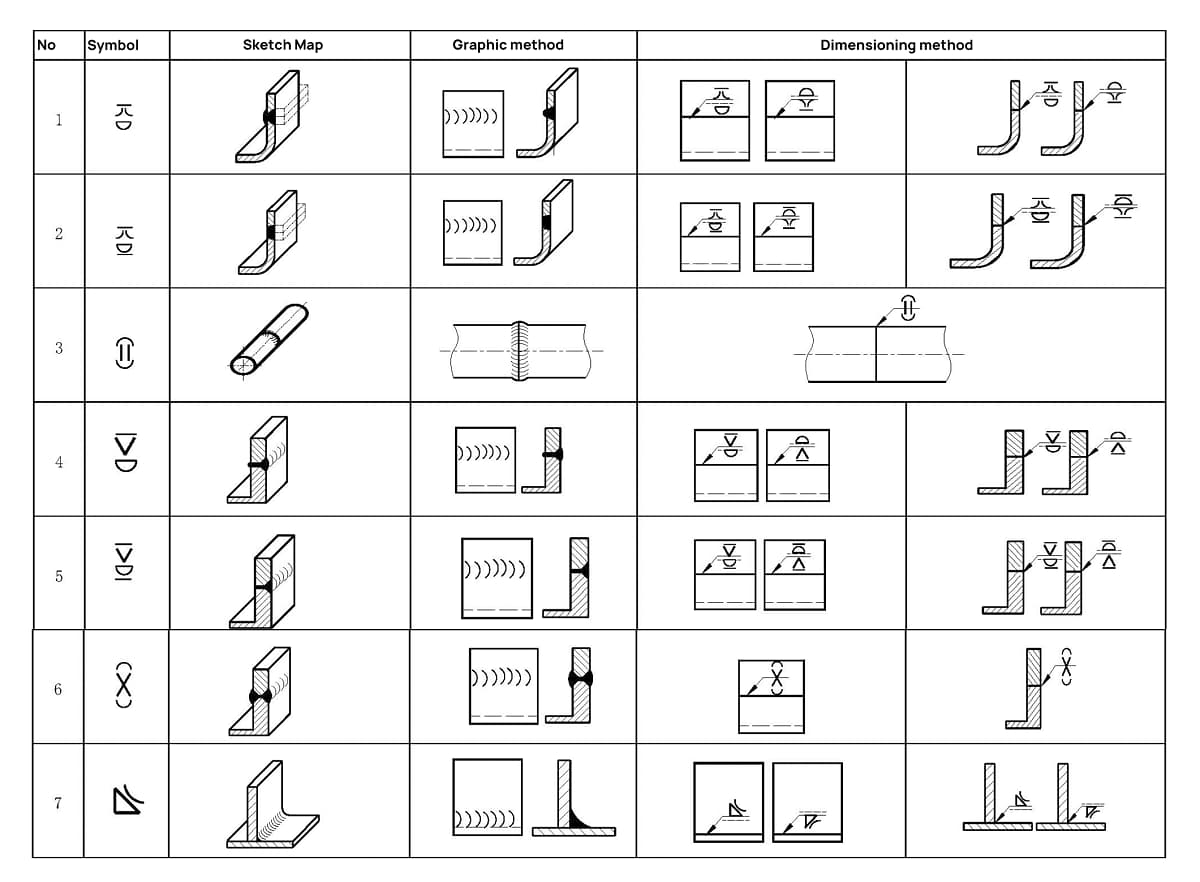
The basic symbol represents the cross-sectional shape of the weld, as illustrated in Table 1.
Table 1 Basic Welding Symbols
Serial No
Symbol name
Sketch Map
Weld symbol
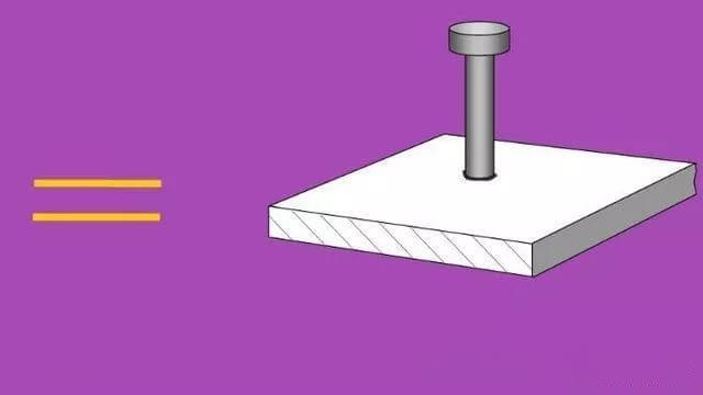
1
Rolled edge weld (fully melted rolled edge)
Note: incompletely melted rolled edge weld is indicated by I-shaped weld symbol, and the effective weld thickness S is added, as shown in Table 7
Supplementary symbols are used to add additional information about the characteristics of the welds. For examples of supplementary symbols, refer to Table 4.
Table 5 Example of supplementary symbol application
Serial No
Sketch Map
Dimension example
Explain
1
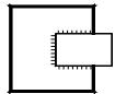
Indicates that there is a backing plate at the bottom of the back of the V-shaped weld
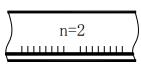
2
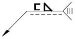
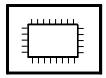
There are welds on three sides of the workpiece, and the welding method is manual arc welding
3
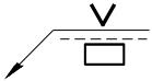
It means welding around the workpiece on site
IV. Position of Welding Symbols on Drawings
1. Basic requirements
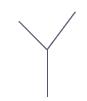
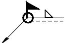
Complete weld representation methods consist of the basic symbol, auxiliary symbol, supplementary symbol, leader, dimension symbol, and data. The leader line is composed of an arrow leader line (also known as an arrow line) and a datum line, which can be either a solid line or a dotted line, as illustrated in Figure 1.
Fig. 1 Leader line
2. Relationship between arrow line and welding joint
Two terms are used to describe the relationship between the arrow lines and the joints:
a. Arrow side of the connector;
b. Non-arrow side of the connector.
Refer to Figures 2 and 3 for a description of these two terms.
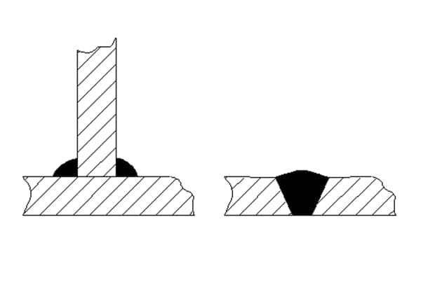
(a) Weld seam on arrow side
(b) Weld seam is on the non arrow side
Fig. 2 T-joint with single fillet weld
Fig. 3 Cross joint of double fillet weld
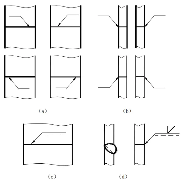
3. Arrow position
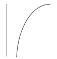
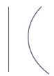
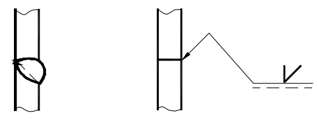
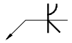
Generally, there is no specific requirement for the position of the arrow line relative to the weld, as shown in Figures 4(a) and (b). However, when marking single-sided V-shaped, single-sided V-shaped with a blunt edge, and J-shaped welds, the arrow must point towards the workpiece with the groove, as shown in Figures 4(c) and (d). If necessary, bending the arrow line once is allowed, as shown in Figure 5.
Fig. 4 Location of arrow line
Fig. 5 Curved arrow line
4. Location of reference line
The dotted line of the reference line can be drawn either above or below the solid line of the reference line. The datum line must be parallel to the bottom edge of the drawing.
5. Position of datum mark relative to datum line
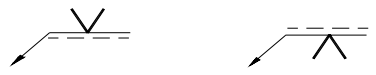
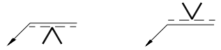
a. If the weld is on the arrow side of the joint, the basic symbol shall be marked on the solid line side of the datum line, as shown in Fig. 6 (a);
b. If the weld is on the non-arrow side of the joint, the basic symbol shall be marked on the dotted line side of the datum line, as shown in Fig. 6 (b);
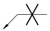
c. When symmetrical welds and double-sided welds are marked, dotted lines may not be necessary, as shown in Fig. 6 (c) and (d).
(a) The weld is on the arrow side of the joint
(b) The weld is on the non arrow side of the joint.
(c) Symmetrical weld
(d) Double side weld
Fig. 6 Position of basic symbol relative to reference line
V. Weld Size Symbol and Its Marking Position
1. Basic Dimensions and Related Concepts of Welds
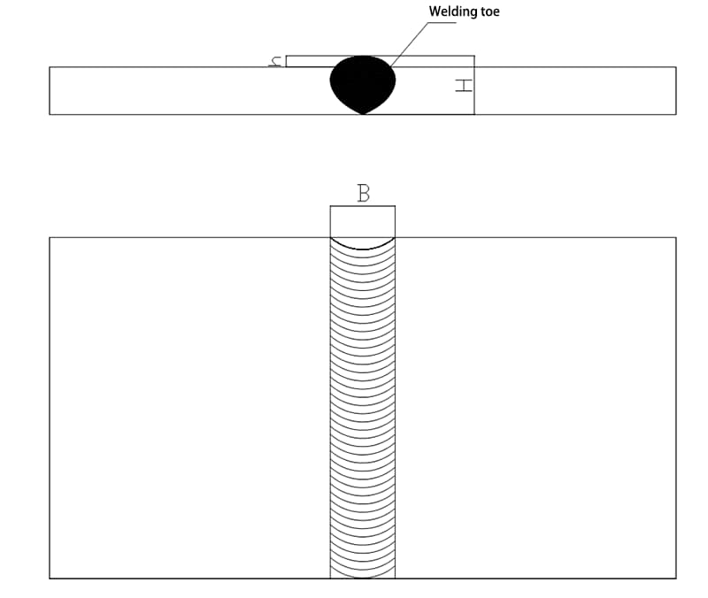
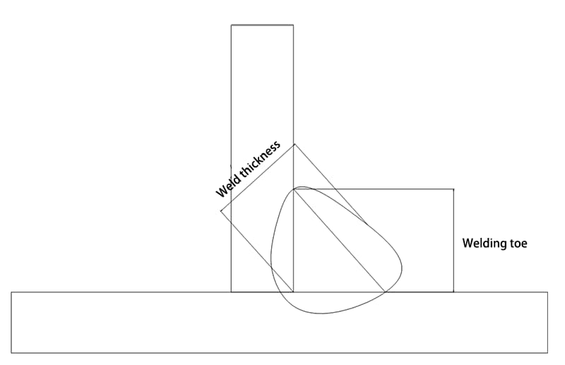
1. Weld Toe:
The junction between the surface of the weld and the parent metal.
2. Weld Width (B):
The distance between the two weld toes on the surface of the weld.
3. Weld Thickness:
In the cross-section of the weld, the distance from the front of the weld to the back of the weld.
4. Leg Size:
The length of the right-angled side in the largest isosceles right-angled triangle drawn in the cross-section of the fillet weld.
5. Weld Leg:
In the cross-section of the fillet weld, the shortest distance from a weld toe on one right-angled surface to another right-angled surface.
6. Penetration Depth:
In the cross-section of the weld joint, the depth of melting of the parent metal or the previous weld seam.
7. Welding Form Factor:
The ratio of weld width B to calculated weld depth H on the single seam cross-section during fusion welding.
8. Reinforcement:
The maximum height of the weld metal that exceeds the line on the surface of the parent metal.
9. Weld Root:
The junction of the back of the weld and the parent metal.
10. Crater
During arc welding, a depression formed at the end of the welding path due to improper arc breaking or arc extinguishing.
11. Weld Pool
During fusion welding, under the influence of the welding heat source, the part of the metal on the workpiece that forms a certain geometric shape and becomes liquid.
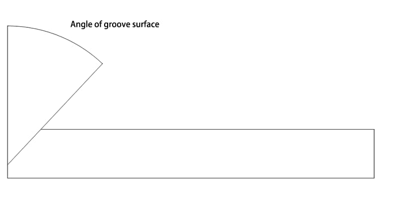
The angle between the end face of the groove to be machined and the groove surface:
2. General requirements
2.1 If necessary, datum symbols can be provided with dimension symbols and data. See Table 6 for dimension symbols.
Table 6 Weld Size Symbols
Symbol
Symbol name
Example diagram
Symbol
Symbol name
Example diagram
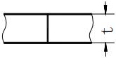
δ
Workpiece thickness
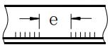
e
Weld spacing
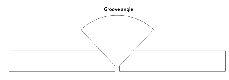
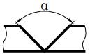
α
Groove angle
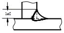
K
Fillet size
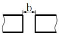
b
Root gap
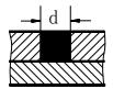
d
Nugget diameter
P
Blunt edge
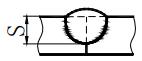
S
Effective thickness of weld
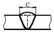
c
Weld width
N
Number of identical welds symbol
R
Root radius
H
Groove depth
L
Weld length
h
Surplus height
n
Number of weld segments
β
Groove face angle
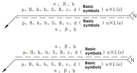
2.2 The marking principles for the weld size symbol and data are illustrated in Figure 7.
a. The dimensions of the cross-section of the weld are indicated on the left side of the basic symbol;
b. The dimension in the length direction of the weld is indicated on the right side of the basic symbol;
c. The groove angle, groove face angle, and root gap dimension are indicated on the top or bottom of the basic symbol;
d. The number symbol for the same weld is indicated at the end;
e. When there are many dimension data to be marked and they are difficult to distinguish, corresponding dimension symbols can be added in front of the data for clarity.
Fig. 7 Marking principle of weld size
2.3 See Table 7 for the example of weld size marking.
Table 7 Example of Weld Dimension
Serial No
Weld name
Sketch Map
Welding dimension symbol
Example
1
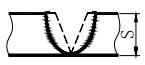
Butt weld
S: Effective thickness of weld
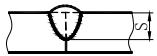
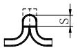
2
Crimping weld
S: Effective thickness of weld
3
Continuous fillet weld
K: Fillet size
4
Intermittent fillet weld
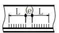
L: Weld length, excluding crater; e: weld gap ;n: number of weld segments
5
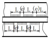
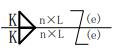
Staggered intermittent fillet weld
L: Weld length, excluding crater;e: weld gap;n: number of weld segments; K: weld fillet size
6
Plug weld or slot weld
L: Weld length, excluding crater; e: weld gap; n: number of weld segments; c: slot width.
e: Weld clearance; n: number of weld segments; d: diameter of hole.
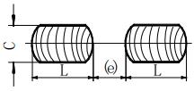
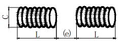
7
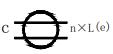
Seam weld
L: Weld length, excluding crater; e: weld gap; n: number of weld segments; c: weld width.
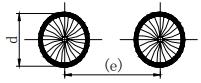
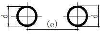
8
Spot weld
n: Number of weld segments; e: spacing; d: weld spot diameter.
3. Description of dimension symbols
3.1 The size for determining the position of the weld shall be indicated on the drawing rather than within the weld symbol.
3.2 If no marking is present on the right side of the basic symbol and no further information is given, it is assumed that the weld is continuous along the entire length of the workpiece.
3.3 If there is no marking on the left side of the basic symbol and no other information is given, it is assumed that the butt weld should be completely welded.
3.4 When the plug weld and groove weld have beveled edges, the size of the bottom of the hole should be marked.
VI. Example of Symbol Application
Appendix A
(Informative appendix)
Example of symbol application
A. 1 Application of basic symbols
See Table A.1 for examples of basic symbols.
A. 2 Basic symbol combination
See Table A.2 for application examples of basic symbol combination.
A. 3 Combination of basic symbols and auxiliary symbols
See Table A.3 for examples of the combination of basic symbols and auxiliary symbols.
A. 4 Special cases
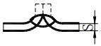
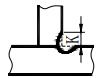
See Table A.4 for the marks of flared weld, unilateral flared weld, stack weld and lock edge weld.
Table A.1 Application examples of basic symbols
Table A.2 Example of basic symbol combination
Table A.3 Examples of combination of basic symbols and auxiliary symbols
Table A.4 Marking of Special Welds
Appendix B
(Normative appendix)
Welding method and its name
B. 1 Marking of welding method in drawings
When various welding methods are marked on the drawings, Chinese characters shall be used instead of the codes specified in GB/T 5185.
B. 2 Common welding methods and their names
Common welding methods and their names are as follows:
a) Manual arc welding (coated electrode MIG welding);
b) Submerged arc welding;
c) MIG welding: Molten inert gas protection welding;
d) MAG welding: Molten non inert gas protection welding;
When a simple representation of the weld is needed in the drawing, it can be shown through views, cross-sectional views, or cross-sectional drawings. This appendix provides a straightforward method commonly used by companies as outlined in GB/T 12212 for ease of use. For more information, refer to GB/T 12212.
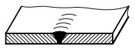
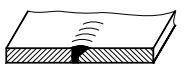
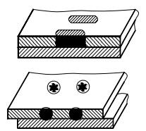
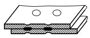
C. 2 Views
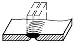
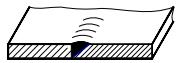
C. 2.1 The drawing method of welds is shown in Fig. C.1 and Fig. C.2 (a series of fine solid line segments representing welds can be drawn by hand).
It is also allowed to use thick lines (2b ~ 3b) to represent welds, as shown in Fig. C.3.
However, in the same drawing, only one painting method is allowed.
Drawing method of welds
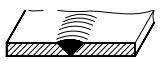
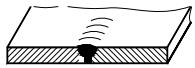
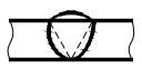
C. 2.2 In the representation of the end face of the weld, a thick solid line is typically used to outline the contour of the weld.
If needed, a thin solid line can be used to depict the groove shape before welding, as depicted in Figure C.4.
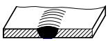
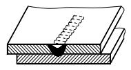
C. 3 Sectional view or sectional view
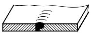
In sectional or profile views, the metal fusion welding area of the weld is typically marked in black, as depicted in Figure C.5. If the groove shape needs to be indicated as well, the fusion welding area can also be represented as outlined in Clause C.2.2, as shown in Figure C.6.
As the founder of MachineMFG, I have dedicated over a decade of my career to the metalworking industry. My extensive experience has allowed me to become an expert in the fields of sheet metal fabrication, machining, mechanical engineering, and machine tools for metals. I am constantly thinking, reading, and writing about these subjects, constantly striving to stay at the forefront of my field. Let my knowledge and expertise be an asset to your business.
Ever wondered what "X-weld" or "tack-weld" means? Our latest article breaks down 292 crucial welding terms, offering clear definitions and practical examples. Whether you're a seasoned welder or just starting,…
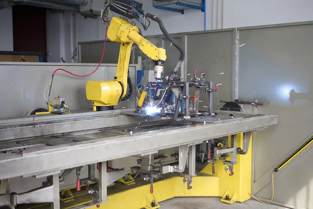
I. Inspection Content for the Welding Robot Body II. Inspection Content for the Welding Robot Control Box III. Inspection Content for the External Axis and Welding Clamp of the Welding…
Imagine a welding technique that offers precision, efficiency, and versatility, all while minimizing defects. Variable Polarity Plasma Arc Welding (VPPAW) achieves just that for aluminum alloys. By independently adjusting current…
Have you ever wondered how welding transforms separate metal pieces into a unified whole? This article explores the fascinating world of weld joints, examining their types, mechanical characteristics, and the…
Imagine turning heavy, bulky welding machines into lightweight, portable powerhouses. This article dives into the mechanics of inverter arc welding power sources, showcasing their transformation of AC to DC for…
Have you ever wondered how thin sheet metal is flawlessly joined in complex machinery? This article explores the fascinating world of welding techniques, from manual arc welding to MIG and…
This article explores the fascinating world of welding, from manual arc welding to advanced gas-shielded techniques. You'll uncover the methods, benefits, and applications of various welding processes. Get ready to…
Ever wondered how metals join to create the world around us? This article dives into the fascinating world of welding, exploring its basic principles, techniques, and the critical role it…
Ever wondered how welding engineers tackle the most common issues in their field? From understanding weld defects to mastering the best techniques for different materials, this article covers 80 essential…