Since 1995, the laser marking industry has seen advancements in large format systems, rotating mirror systems, and vibrating mirror systems. The control mode has also evolved from software direct control to upper and lower computer control, to real-time processing and time-sharing reuse.
Nowadays, the rise of semiconductor lasers, fiber lasers, and ultraviolet lasers presents new challenges for optical process control.
The latest product in the field is the galvanometer laser marking head (galvanometer scanning system).
The large-scale application of galvanometer scanning systems in China began in 1998. The galvanometer, also known as an ammeter, is designed based on the same principles as an ammeter.
Instead of a needle, the galvanometer uses a lens, and the computer-controlled DC signal of -5V to +5V or -10V to +10V replaces the probe signal to perform the desired action.
Like the rotating mirror scanning system, this control system uses a pair of turn-back mirrors. The difference is that the stepping motor driving the lens has been replaced by a servo motor. Additionally, the use of a position sensor and a negative feedback loop design further enhance the accuracy of the system, leading to improved scanning speed and repeated positioning accuracy.
Galvanometer scanning marking
The Galvanometer Scanning Marking Head is mainly composed of an XY scanning mirror, a field mirror, a galvanometer, and computer-controlled marking software. The appropriate optical components are selected based on the laser wavelength. The system may also include a laser beam expander and laser.
The working principle of the Galvanometer Scanning Marking Head involves incident laser beams on two scanning mirrors, whose reflection angles are controlled by a computer. These two mirrors can scan along the X and Y axes, respectively, resulting in the deflection of the laser beam and the movement of the laser focus with a specific power density on the marking material. This leaves permanent marks on the material surface.
The focused spot can be either circular or rectangular. The galvanometer scanning system can be used for vector graphics and text and utilizes the graphics processing method of the computer’s graphics software. This method boasts high drawing efficiency, accurate graphics, and no distortion, improving the quality and speed of laser marking.
In addition, the galvanometer marking can also adopt the dot matrix marking method, making it suitable for online marking. Depending on the production line speed, one or two scanning galvanometers can be used. Compared to array marking, the dot matrix information that can be marked is more extensive, making it ideal for marking Chinese characters.
The Galvanometer Scanning Marking Head has become a popular product due to its wide range of applications, vector and dot matrix marking capabilities, adjustable marking range, fast response speed, high marking speed (marking hundreds of characters per second), high marking quality, strong optical path sealing performance, and adaptability to various environments. It is considered to be the future of laser marking and holds significant application prospects.
Laser marking head
The double-headed marking head (also referred to as a double-headed marking head) consists of two scanning heads.
Once a laser beam enters the marking head, it is split into two laser beams through optical combination.
Special double-headed marking software controls each of the two heads separately.
Its marking efficiency is double that of a single head and the marking area is also twice as large.
It is especially suitable for applications that require fast and large-area marking.
The technical specifications of the double-headed model are the same as those of the single-headed model, with the exception of a doubled marking area.
For example, if the marking area of the single-headed model is 100x100mm, the corresponding double-headed model would have a marking area of 200x100mm.
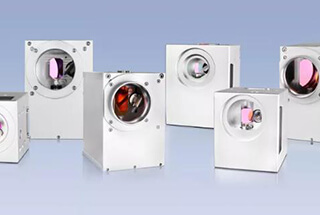
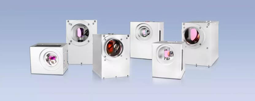
Optical elements
We carefully optimize and troubleshoot all optical components to ensure optimal focusing quality and stable processing parameters.
Our optical products feature a compactly designed objective lens, including an adapter for standard objective lenses, as well as optical components with varying wavelengths, power density, focal lengths, and fields of view.
Digital laser marking head
Compared to traditional analog marking heads, digital marking heads boast notable advantages such as a compact size, fast scanning speed, and robust resistance to interference.
They are primarily used in optical fiber laser marking machines, end-pumped solid laser marking machines, and flying laser marking machines.
Digital header features
- Compared to traditional online inkjet methods, laser online marking has the benefits of faster speed (up to 100 M/min), increased efficiency, exceptional anti-counterfeiting capabilities, compliance with European environmental protection standards, and significantly reduced operational costs.
- The flight marking head can be combined with various lasers to create a flight laser marking machine.
- This technology has the advantages of ease of use, a wide range of applications, and suitability for marking on various materials.
Application industry
The laser flight marking machine produced using the flight marking head has a wide range of applications in industries such as medicine, personal care products, tobacco, food and beverage packaging, alcohol, dairy products, clothing accessories, leather, electronic components, chemical building materials, and more. It can also be used to mark graphics and text, such as expiration dates, batch numbers, shift information, manufacturer names, and logos.
This machine is suitable for online marking on a variety of materials, including paper packaging, leather, plexiglass, resin plastic, bamboo and wood products, coated metal, and PCB boards.
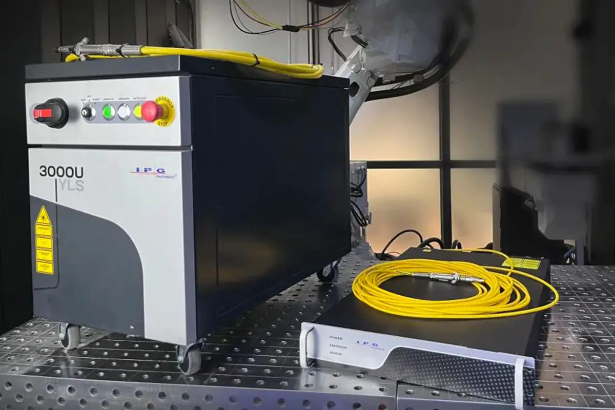
Typical application
Laser processes including drilling, cutting and welding, deep engraving, rapid prototyping, rapid processing, microstructuring, and 3D workpiece processing.
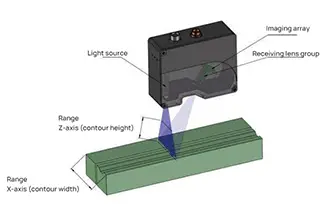
Working Principle
During the scanning process in a laser galvanometer, the divergent lens within the device is moved relative to the focusing lens by a motor, allowing for dynamic and precise positioning along the optical axis.
This movement modifies the overall focal length of the system, working in synchrony with the scanning deflection lens, expanding two-dimensional scanning into a three-dimensional scanning system.
The device can substitute for the costly flat field objective lens in two-dimensional scanning applications and also enable three-dimensional beam deflection scanning systems.