Laser Engraving Speed Chart: 12 Types of Materials
Have you ever struggled with finding the perfect laser engraving speed? In this blog post, we'll explore the ins and outs of laser engraving speed charts. Our expert mechanical engineer…
Ever wondered how intricate designs are etched onto various materials with such precision? This article dives into the fascinating world of laser engraving machines, detailing their operation, safety measures, and key features. From installation tips to focusing adjustments, you’ll gain insights into maximizing efficiency and ensuring safety while working with these high-tech devices. Get ready to explore the essentials and complexities of laser engraving, ensuring your projects turn out flawless.
★ Prior to operating the equipment, users must diligently read this operation manual and strictly adhere to the operating procedures.
★ Laser processing may pose risks. Users should carefully consider whether the object to be processed is suitable for laser operations.
★ The processed object and its emissions should comply with local laws and regulations.
★ This equipment uses a Class 4 laser (intense laser radiation) that may cause the following accidents:
1. Ignite nearby flammable materials.
2. During laser processing, depending on the object being processed, other radiation and toxic or harmful gases may be generated.
3. Direct exposure to laser radiation can cause bodily harm.
Therefore, the location where the equipment is used must be equipped with firefighting equipment, and the accumulation of flammable or explosive items around the workstation and equipment is strictly prohibited. Ventilation must be maintained at all times.
★ The environment where the equipment is located should be dry, free from pollution, vibration, strong electricity, and magnetic interference. The operating environment temperature should be between 10-35°C, and the humidity should be 5-95% (no condensation).
★ The working voltage of the equipment is AC220V, 50HZ. Do not turn on the machine when the grid voltage is unstable or mismatched.
★ The engraving machine and any related equipment must be grounded securely before operation.
★ When the equipment is on, it must be attended by a dedicated person. In case of an anomaly, all power supplies should be immediately cut off, and corresponding measures should be actively taken. All power supplies must be cut off before leaving, and unauthorized leaving is strictly prohibited.
★ Do not place any irrelevant total reflection or diffuse reflection objects in the equipment to prevent laser reflections on the human body or flammable items.
★ The equipment should be kept away from electric devices that are sensitive to electromagnetic interference as the equipment may generate electromagnetic interference.
★ There are high voltages or other potential dangers inside the laser equipment. Dismantling by non-professionals is strictly prohibited.
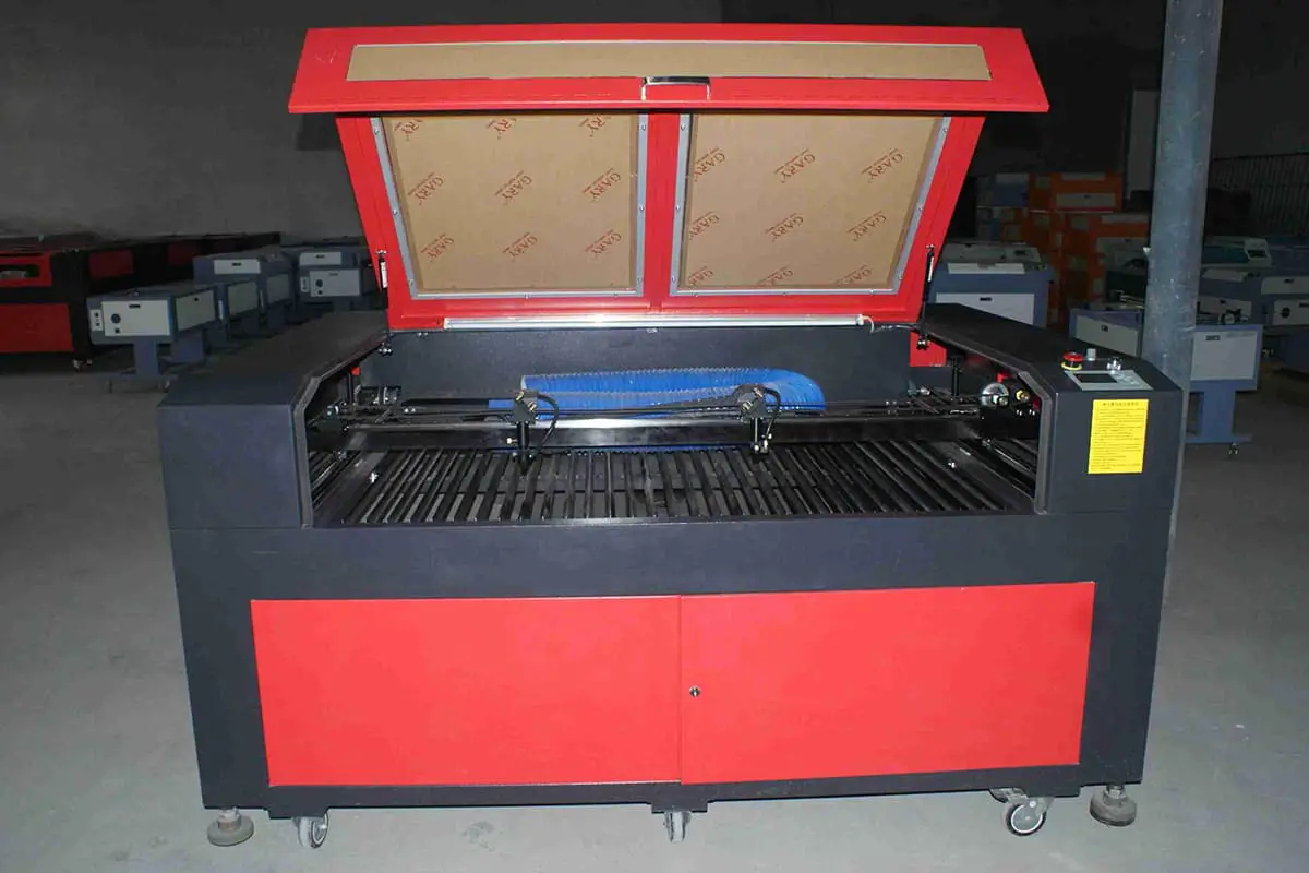
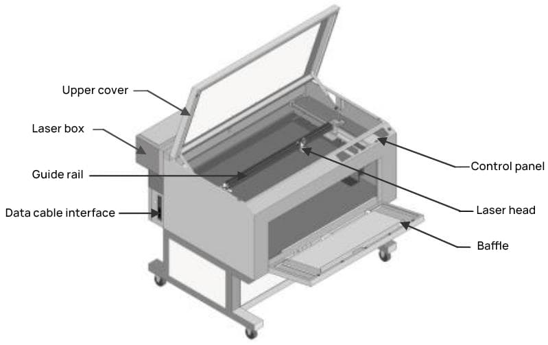
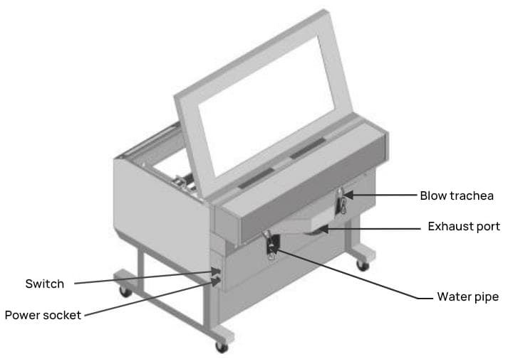
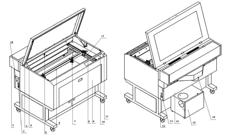
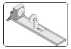
The machine’s appearance is as shown in Figures 1-1 and 1-2:
In addition to the main engraving machine, your package should include the following accessories (subject to physical item; optional accessories are not included in the package):
 Water Pump | 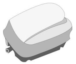 Air Pump | 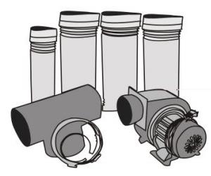 Centrifugal Blower, Exhaust Pipe, Tee Joint |
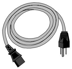 Power Cord | 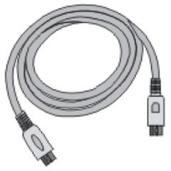 Data Cable (Printer Cable) | 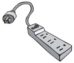 Bull Plug Socket |
 ACE Software, Founder Font Library | 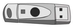 Encryption Dongle |
The D-series laser engraving machine (hereinafter referred to as the engraver) is a high-tech product integrating optics, mechanics, and electronics, controlled by a computer for laser operation. It includes two models: D80M and D80RF, with the following features:
Wide Range of Applications
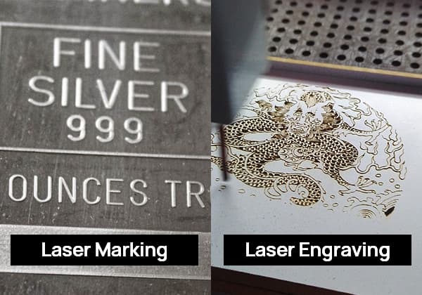
The engraver offers two processing methods: cutting and engraving. Cutting refers to the machine processing along the outlines of graphics or text, capable of color-segmented cutting, i.e., cutting to different depths depending on the colors of lines set in the software. Engraving refers to processing the entire graphic or text row by row according to a bitmap.
In engraving mode, it can perform gradient engraving, that is, engraving a slanted surface at the base of the raised lines to increase their strength, suitable for making seals and printing rubber plates. The scanning mode can create halftone images, using the density of points to represent the depth of color, with the final product resembling a black-and-white photo.
This engraver can be used for cutting and engraving textiles and leather, as well as for the production of handicrafts, signs, etc.
Versatility of Materials
Suitable for common non-metal materials such as bamboo, wood, acrylic, plastic, leather, two-tone plates, textiles, paper, rubber, etc.
High Processing Quality
With a resolution precision of 0.025mm, it provides smooth cutting lines, no serrated edges, small gaps, and precise curve fitting. During engraving and scanning, it can accurately output bitmap images, with fine mesh points. The engraved or scanned images and photos can compete with those produced by imported laser engravers.
Ease of Use
The engraver comes with our company-developed ACE Art Engraving software, which is user-friendly and available in both Chinese and English versions. Users can also install a print driver system to directly edit and output files from various Windows-based applications such as Photoshop, CorelDraw, Word, AutoCAD, etc.
Ingenious Structure
Equipped with an automatic lift table, it can process workpieces up to 250mm thick.
The front and rear of the machine case are interconnected, allowing for unlimited Y-direction material feeding, thereby increasing the processing area.
The worktable is flexibly configured and can be adjusted according to different processing methods and materials.
Excellent Working Environment
It’s clean, has low noise, and can minimize waste to the greatest extent, thereby reducing costs.
1.4. Main Technical Parameters
| Model | D80M | D80RF |
| Working Surface (mm) | 800*500*250(X*Y*Z) | |
| Z-Axis Travel of Work Table | 0-250(mm) | |
| Operation Mode | Engraving/Scanning/Cutting | |
| Scanning Speed (mm/s) | Adjustable from 0 to 800 mm/s | |
| Cutting Speed (mm/s) | Adjustable from 0 to 3800 mm/s | |
| Slope Engraving | 360° slope, with freely adjustable slope size | |
| Color Marking | Up to 256 layers of color separation cutting, different colors can control different speeds, energy levels, sequences, and other parameters | |
| Laser Beam Quality | Domestic lasers: 1.4±0.3, imported lasers: 1.2±0.2 | |
| Laser Spot Diameter | Domestic lasers: 6±2mm, imported lasers: 4±1mm | |
| Resolution | 10000dpi | |
| Positioning Accuracy (mm) | 0.025 mm | |
| Working Voltage (V) | 220V 50HZ | |
| Total Power | 800W | |
| Dimensions (mm) | 1250*1120*1060 | |
| Net Weight (kg) | 140 kg | |
| Laser Device | 40W CO2 Glass Laser/30W Imported Radio Frequency Packaged Metal Laser | |
| Optical System | American-imported optical components, accurately positioned with a red light positioning system. | |
| Operating System | Windows98/2000/XP | |
| Language Supported | Switching between Chinese and English is seamless, with multi-language interface options available based on customer requirements. | |
| Interface Software | Genuine Zhengtian dedicated drawing software, AutoCad, CorelDraw, Photoshop, CAXA, and others. | |
| Software Features | The authentic Zhengtian driver uses a unique intelligent prediction algorithm and an improved control algorithm. Based on the Windows platform, this driver provides an array of features, treating the device as a standard Windows printer. It can be directly output from various layout software such as Word, Coreldraw, Photoshop, Autocad, CAXA, making it more convenient to use. With our independently developed path optimization system, processing efficiency can be increased by 30%-50%. | |
| Control Mode | The embedded motion control platform, equipped with an expansive storage system, can simultaneously store 99 files, demonstrating high-speed data processing. It ensures prompt processing and output, offers human-machine dialogue capabilities, and allows parameter setting operations directly from the control panel interface. | |
| Key Features | Automatic height adjustment platform features, cylindrical engraving and cutting capabilities. | |
| Safety Protection System | Forced water cooling protection system; water temperature safety control system; temperature control automatic alarm system; automatic pause function when the work cabin is opened; enclosed light path operation mode. | |
| Device Interface | USB transmission enables one-to-many and many-to-one control. It supports local area network output and can be used offline. | |
| Rotary Attachment (Optional) | Clamping cylinders with diameters ranging from 8 to 150 millimeters. | |
A complete working system consists of the main unit of the laser engraving machine, the laser, water pump, water tank, air pump, centrifugal fan, exhaust pipe, exhaust fan or air purifier, communication cable, etc. According to work needs, users configure their own computer, printer, scanner, etc.
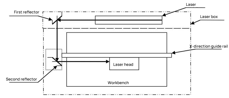
To ensure transportation safety, the laser is packaged separately; thus, the laser needs to be installed first, as shown in Figure 2-1.
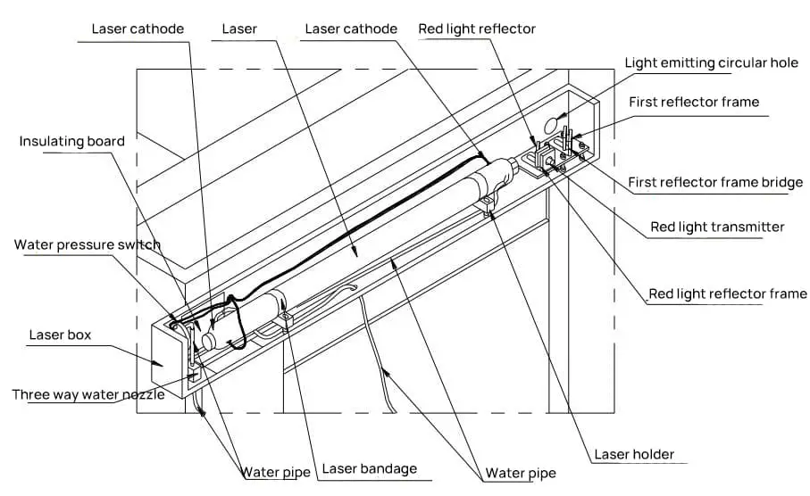
Step One: Open the laser box at the back of the main unit and take out the laser tube.
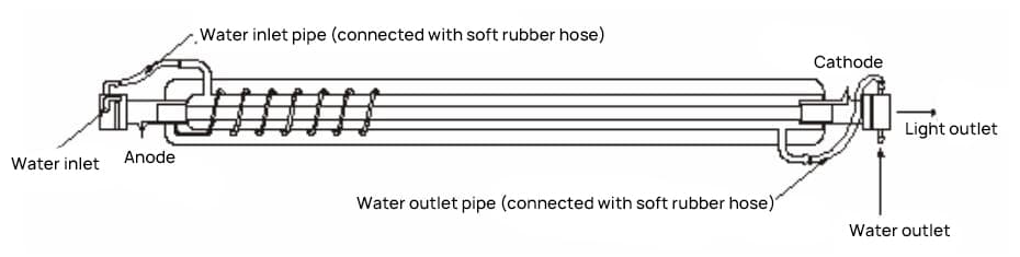
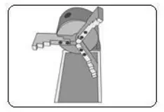
The end of the laser that emits light is the negative pole, with a circular hole at the negative end; the positive end is solid, and the spiral return air tube in the laser is often at the positive end (as shown in Figure 2-2).
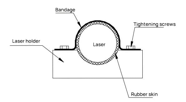
Step Two: Fix the laser to the laser seat in the laser box.
First, fix one side of the laser strap to the laser seat with an M4 screw (Note: do not tighten it first), wrap the green rubber around the appropriate position on the laser with crepe paper, place the part of the laser wrapped with green rubber on the laser seat, tighten the screws on both sides of the strap, and fix the laser to the laser seat (Note: after tightening, the laser cannot move and the strap has already touched the gasket on the screw, but don’t use too much force to avoid breaking the laser). As shown in Figure 2-3.
Step Three: External wiring of the laser.
Connect the positive and negative wires of the laser (the end of the laser that emits light is the negative pole, the positive end is solid, there is a circular hole at the negative end, and the spiral return air tube in the laser is often at the positive end).
Connect the positive pole to the red high-voltage line, and the negative pole to the negative yellow line. The method is: wind the metal wire in the electric wire around the tungsten rod of the laser, put on the protective rubber tube, and inject 703 glue to completely submerge the exposed conductive part (as shown in Figure 2-4).
Note: Be sure to insulate the high voltage properly, otherwise it is likely to cause danger.

Step Four: Connect the inlet and outlet pipes to the laser water inlet and outlet with soft rubber hoses respectively (as shown in Figure 2-2).
Slightly rotate the laser tube, adjust the position of the outlet pipe so that its vertical height is lower than the inlet pipe. Then tighten the fixing screw of the laser seat.
The right side of the engraving machine’s enclosure houses the power socket, data interface, and power switch (as shown in Figure 2-5).
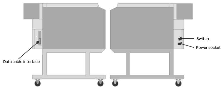
Step 1: Connect the power cord to a 220V/50Hz AC power source to supply electricity to the machine.
Step 2: Connect one end of the data cable to the data interface of the machine and the other end to the computer to transmit data to the engraving machine.
Note: Do not turn on the power of the engraving machine until the cooling water system is properly set up.
Glass tube lasers generate heat during operation. If not cooled in time, the lasers can rupture and damage, and the cooling water can affect the normal light emission of the lasers. Hence, maintaining a good water circulation is extremely important during the operation of the engraving machine.
Note: The cooling water circulation must be turned on before operating the laser engraving machine.
The connection method for the cooling water is as follows:
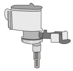
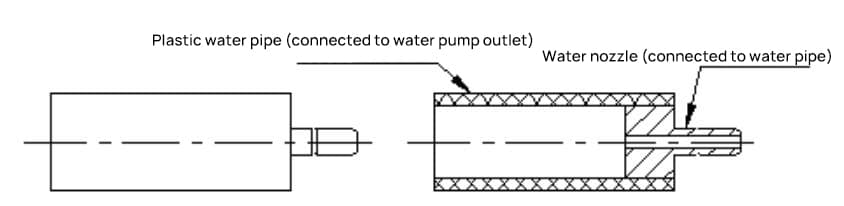
Step 1: The water pump package includes a water nozzle (as shown in Figure 2-8).
Place one end of the plastic water tube on the water nozzle into hot water. Once the plastic tube expands slightly, insert it onto the water outlet of the pump to serve as a transition between the pump outlet and the machine’s water inlet.
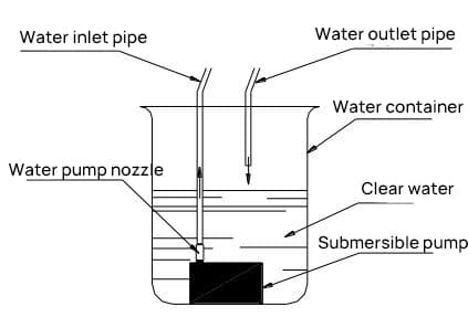
Step 2: Fill a container of over 5 liters with clean water and place the water pump in it.
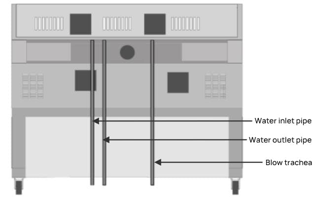
Step 3: Connect the “water inlet pipe” outside the laser box to the water nozzle on the water pump, and place the other “water outlet pipe” directly into the water container. (The water inlet pipe is connected from the three-way water nozzle inside the laser box.)
Step 4: Turn on the power to the water pump and observe the circulation of the cooling water. You can determine whether the cooling water circulation is normal as follows: Pick up the water pipe in the container that is not connected to the water pump.
If the water flows smoothly and stably, it means that the cooling water system is working well. If there is no water flow or the flow is not smooth, please check whether the water pipe and water pump are damaged, and whether the water pipe is connected properly.
2.4.1. Connecting the Air Pump
Insert the blower pipe at the back of the engraving machine (see Figure 2-6) into the air pump. After turning on the power to the air pump, the blowing port of the laser head will start working.
Blowing air on the material being processed during machining not only quickly cools the surface but also blows away any debris produced during machining, ensuring the quality of the work.
2.4.2. Dust Removal System
The D series engraving machine uses rear exhaust. The exhaust is used to expel waste gases produced when processing non-metallic materials.
First, fix the rear exhaust box on the back of the enclosure, connect the exhaust pipe to the exhaust port, and connect the exhaust fan or air purifier through a three-way tube, as shown in Figure 2-9:
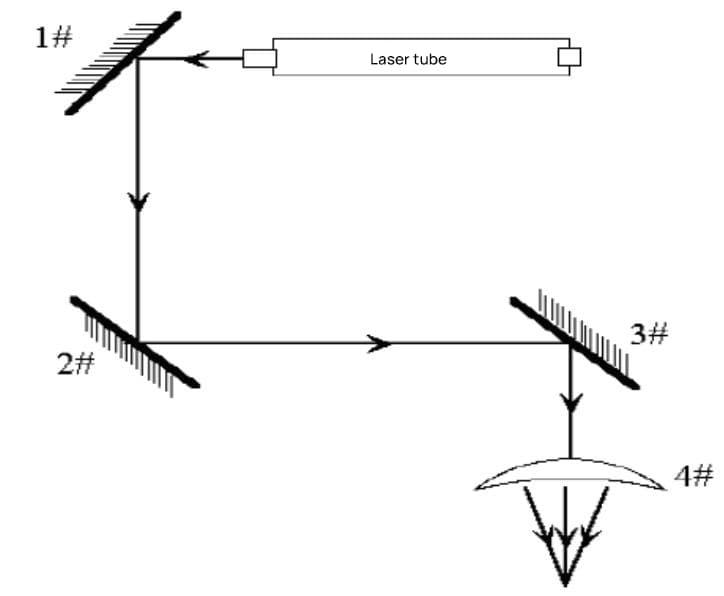
The laser engraving machine is a precise optical instrument, and the requirements for light path adjustment are high. If the laser is not shot from the center of each lens, it will affect the engraving results.
Therefore, light path adjustment is extremely important during the installation and use of the laser engraving machine. Pay attention to the following when adjusting the light path:
The laser is invisible, so do not place your body in the light path to avoid being burned by the laser. When adjusting the light path, try to let the enclosure block your body and stand where the light cannot reach.
Before adjusting the light path, you need to connect the external wiring, install the cooling water and dust removal ventilation system, and ensure that the machine is well grounded. Do not adjust the light path when the cooling water circulation is not good.
2.5.1. Determining the Laser Beam Entry Point
When adjusting the light path, the first step is to determine the entry point of the laser beam, which is done as follows:
Step 1: Turn the current on the ammeter to zero, press the “High Voltage Emission” button, then press the “Manual Emission” button, adjust the current so that the output current is small (around 4 milliamperes), capable of piercing the polyester film in 2 seconds, and then lift the “Manual Emission”.
Step 2: Take a piece of transparent polyester film used for positioning and cover it in front of the lens (Note: the film should not be too close to the lens, to avoid contaminating the lens with melted material when the laser burns the film), quickly press the “Manual Emission” button and then lift it.
The position where the laser beam burns a round hole on the film corresponds to its entry point on the lens (sometimes two round holes are burned on the film, the smaller one is burned by the beam reflected by the lens, and the angle formed by the incident point and the reflection point can roughly show the direction of the light path).
When the two reflecting mirrors are far apart, you should first find the direction of the light path between the two mirrors. The specific method is: Insert the polyester film into the light path between the two mirrors, and move from the position close to the previous mirror to the next mirror, find the light path from near to far, and each time the polyester film moves a certain distance, press the “Manual Emission” button and then lift it, requiring each laser to hit the polyester film, so as to find the direction of the light path between the two mirrors.
Note: Before adjusting the light path, you should first ensure that the light emission point of the laser and the center of the first reflecting mirror holder are roughly at the same horizontal height, and make the reflected light of the first reflecting mirror can be shot out from the light hole on the laser box, and at the same time ensure that the center of the first reflecting mirror and the second reflecting mirror are at the same horizontal height.
If it is found that they are not at the same horizontal height, you need to adjust the height of the first reflecting mirror holder bridge and the laser.
2.5.2. Principle of Light Path Adjustment
The adjustment of the light path is mainly achieved by adjusting the deflection angle of the mirror. There are three screws behind the 1st and 2nd mirror holders, and the extension and contraction of the screws determine the angle of the mirror. The specific principle is shown in Figures 2-10 and 2-11:
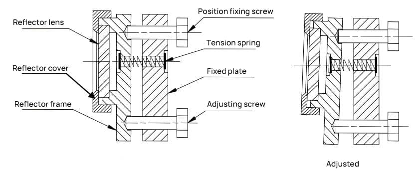
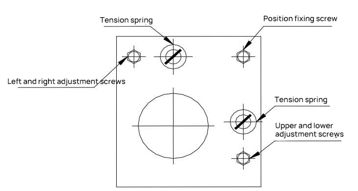
When adjusting the left and right adjustment screws of the previous mirror bracket, the bracket will rotate around the vertical axis formed by the position fixing screw and the up-down adjustment screw, causing the point of incidence on the subsequent mirror to move left or right.
When adjusting the up-down adjustment screw, the mirror will rotate around the horizontal axis formed by the position fixing screw and the left-right adjustment screw, causing the point of incidence on the next mirror to move up or down.
When adjusting the position fixing screw, the mirror will rotate around the oblique axis formed by the left-right adjustment screw and the up-down adjustment screw, causing the point of incidence on the next mirror to move simultaneously in both left-right and up-down directions.
Due to the large size of the machine and the long light path between the previous and subsequent mirrors, you should make minor adjustments to the three adjusting screws on the mirror when adjusting the light path.
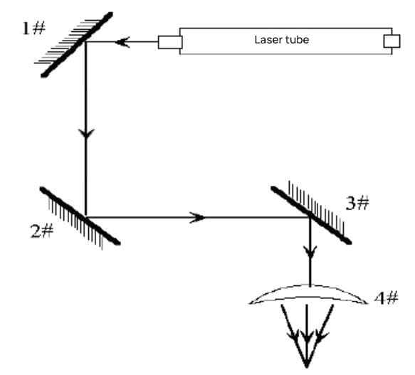
2.5.3. Light Path Adjustment Method
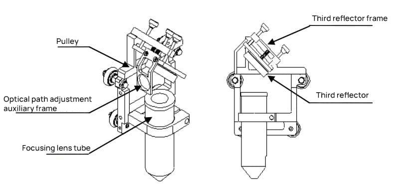
The machine light path and laser head structure are shown in Figures 2-12 and 2-13:
When adjusting the light path, first adjust each mirror to be approximately perpendicular to the horizontal surface and maintain a 45° angle with the X direction. At this time, the lengths of the three adjustment screws between the mirror bracket and the bracket fixing plate should be roughly the same.
Step 1: First adjust the light beam emitted from the laser tube to hit the center of mirror #1 (method refer to 2.5.1).
Step 2: Attach double-sided tape (or other mark-making material) to the light path adjustment bracket of mirror #2, move the crossbeam to the position closest to the laser tube, spot shoot (control appropriate light intensity), and make a mark (note: to prevent laser radiation from harming people, first use a piece of cardboard to test the approximate position of the light spot, then adjust).

Step 3: Gradually move the crossbeam to the position furthest from the laser tube, spot shoot, and make a mark.
Step 4: If the two marks do not coincide, adjust mirror #1 to align the centers of the two marks.
Step 5: Repeat steps two to four until the centers of the two marks completely overlap.
Step 6: Attach double-sided tape (or other mark-making material) in front of mirror #3, move the trolley (laser head) to the position closest to mirror #2, spot shoot (control appropriate light intensity), and make a mark.
Step 7: Gradually move the trolley (laser head) to the position furthest from mirror #2, spot shoot (preferably first use a piece of cardboard to test the approximate position of the light spot to prevent injury), and make a mark.
Step 8: If the two marks do not coincide, adjust mirror #2 to align the centers of the two marks.
Step 9: Repeat steps six to eight until the centers of the two marks completely overlap.
Step 10: Attach double-sided tape to the light entry point of the focusing lens barrel under mirror #3, spot shoot, and make a mark. If it is at the center, it passes.
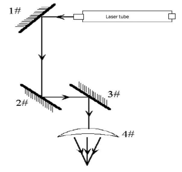
Step 11: If the laser does not fall in the center of the light entry point, as shown in the figure below:
Vertical deviation: The laser tube can only be raised or lowered.
Horizontal deviation: The laser tube can only be adjusted inward or outward.
In this case, the landing point is above and outside. Therefore, the laser tube must be lowered, and then, start over from the first step.
Note: The above work must be performed by an operator who has undergone professional training.

Effective engraving requires a small laser spot and concentrated power. Only with these two conditions can the engraving’s precision and depth be ensured. When the laser beam is first emitted from the laser, its diameter is about 3 millimeters, the power density is low, and it cannot engrave.
After being focused by the focusing lens, the beam at the focus is thinner, with a diameter of about 0.1 millimeter and is the optimal position for engraving. Therefore, fixing the plane to be engraved at the focal point of the focusing lens is a prerequisite for successful engraving.
2.6.1. Simple Focusing
The focusing lens is installed inside the focusing lens tube. After loosening the lock screw on the pen-style laser head clamp, the focusing lens tube can move up and down within the clamp (see Figure 2-14). The focal plane is 8mm below the bottom edge of the focusing lens tube. The machine accessories include an 8mm thick acrylic focusing block to determine the focal plane.
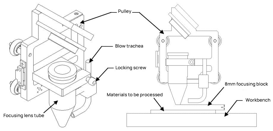
When adjusting the focal length, place the material to be processed on the workbench, then place the focusing block on the surface of the material. Loosen the lock screw on the pen-style laser head clamp, move the focusing lens tube up and down so that the bottom surface of the lens tube is touching the glass block. At this point, the surface of the material to be processed is on the focal plane. Adjust the focal point height as needed, and then tighten the lock screw.
2.6.2. Complex Focusing
The focal length is determined by the focusing lens, and different focusing lenses may have slightly different focal lengths. Therefore, when a new focusing lens is replaced, the position of the focusing lens tube should be readjusted as follows:
Step one: Press the “high voltage switch”, then press the “manual light emission” button, adjust the laser output current to about 5 milliamperes, and then lift the “manual light emission” button.
Step two: Find the focal point.
1) Tilt the acrylic glass and place it on the workbench, its side surface is at an angle of about 50 to 60 degrees with the surface of the workbench.
2) Using the movement buttons on the control panel, move the focusing lens to an appropriate position above the acrylic glass.
3) Press the “manual light emission” button and move the focusing lens along the X direction, let the laser draw a line that is thick at both ends and thin in the middle on the transparent acrylic glass. Then lift the “manual light emission” button. The thinnest point on the line is the position of the focal point.
Step three: Measure the distance from the thinnest point on the transparent acrylic glass to the bottom surface of the focusing lens tube. This distance can be used as a reference value for adjusting the focal point height of the focusing lens during later engraving.
Turn on the power switch, and only after ensuring good cooling water circulation, you can press the “high voltage switch” and “manual light emission” buttons, adjust the output current by turning the current adjustment knob on the control panel. At this point, the laser is emitting light.
Warning: The laser emits invisible light, so remember not to insert your hand into the optical path to prevent burns. You can insert a positioning polyester film into the optical path to determine whether the light is emitted.
Voltage
The external voltage should use the standard 220V/50Hz voltage. High or low and unstable voltages will affect the operation of the engraving machine, common issues may include data transmission errors, unstable laser power, shortened lifespan of the laser, etc. If there are problems with the power supply voltage, a voltage stabilizer should be installed.
Temperature
To ensure the normal operation of the circulating water, the ambient temperature must be maintained between 10℃~35℃. When the room temperature is high or the engraving time is long, pay attention to monitoring the temperature of the circulating water. High water temperature will weaken the cooling effect and affect the normal light emission of the laser. If necessary, increase the amount of circulating water in the container and change the water frequently.
Humidity
High voltage environment exists inside the engraving machine, and high humidity can easily cause high voltage ignition, which is very dangerous, so engraving in a too humid environment is strictly prohibited, and the inside of the machine case should be kept dry.
In addition, too dry environments and air conditioners can easily cause static electricity to accumulate on the surface of the machine case, causing data transmission errors, which should also be avoided. A good grounding can discharge static electricity, especially if the power supply does not have a ground wire, it must be grounded according to the method introduced in Chapter 2.
Water
Cooling water is critical to the engraving machine. If the tap water is too hard, it should be replaced with pure water to prevent scale deposits from blocking the laser. The circulating water should also be kept clean.
Cleanliness
Processing plastic, leather, and rubber will produce corrosive acid deposits, which not only destroy the coating of the lens but also cause irreparable damage to the circuit board. Therefore, the engraving residues should be cleaned every day, and all rust-prone parts should be wiped with machine oil.
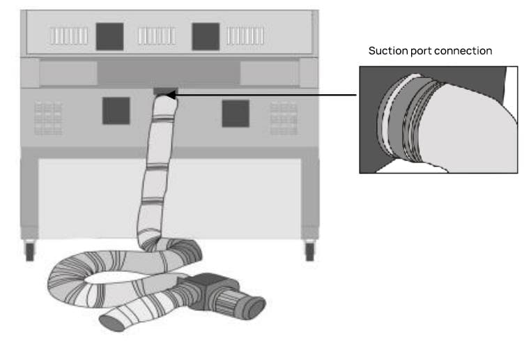
Ensuring the ventilation and dust removal system is unobstructed is also important. The suction port, exhaust pipe, and exhaust fan should be disassembled and cleaned regularly to ensure the smooth exhaust of processing waste gas and dust.
The control panel is located at the front right of the machine, responsible for current adjustment, manual light emission, and manual control of the engraving machine’s X and Y movement. As shown in Figure 3-1:

The functions of the various components on the control panel are as follows:
RST Button: Soft reset button. When pressed, the current processing file is canceled, and the device resets to the top-right starting position.
↑Button: Menu selection button. Used to select menus on the LCD screen.
Light/↓Button: Multi-function button. Menu down selection button. When the screen displays “Adjust light path (on)”, this button controls the light path switch. Pressing this button emits light from the laser. Pressing the “OK” button and “Esc” button controls the worktable’s elevation.
OK Button: Change the light path status; enter the next level menu; confirm and save changes; after storing the data in memory, pressing this button can repeat the output of the data stored in memory.
Esc Button: Exit the current menu, return to the previous menu; cancel the saving of changes.
Laser Head Positioning Button: Consists of up, down, left, and right directional buttons. In offline work mode (when the computer has not sent data to the engraver), pressing any of these buttons will move the laser head in the direction indicated by the arrow.
F Button: Positioning button. When pressed, the indicator light in the upper right corner of this button lights up, and the current position coordinates of the cart are set as the processing origin.
Up Button: Press this button to elevate the worktable surface.
Down Button: Press this button to lower the worktable surface.
Current Adjustment Knob: This knob adjusts the output current, turning right increases it, turning left decreases it. Pressing both the “high voltage switch” and the “manual light output” at the same time, you can see the size of the output current on the ammeter. (Note: During adjustment, first move the focusing lens out of the material to prevent burning the processing material.)
High Voltage Switch: After pressing this switch, the laser power supply will provide high voltage to the laser according to the command. Before each engraving, please make sure to press the high voltage switch, otherwise, the laser will not emit light.
Manual Light Output: After pressing the “high voltage switch”, press this switch again, and the laser will continuously emit light according to the current size indicated by the “output current”.
“!” Button: Hard reset button. After pressing this button, the device restarts, the data interface reconnects, and it restores to the initial state after booting.
Ammeter: The reading on the ammeter is the actual output current of the engraver, which is related to the output power of the laser. The current of the engraver can be adjusted.
Liquid Crystal Display: Upon startup and self-inspection, the following options appear on the display screen:
Press the OK button to change the light path status.
Use the upward arrow key to navigate through the menu. Press the OK button to switch to Light Path Adjustment mode, and the display will show:
At this point, press the light/downward arrow key to manually produce a laser beam, which can be used to adjust the light path and focus.
When the engraving machine is operating, the display shows:
This corresponds to the time required for the file to be processed.
During this time, the red light on the BUSY indicator is on. Pressing the pause button triggers a buzzer sound and causes the red light to flash.
Step 1: Install the laser, connect the cooling water and dust exhaust system (see details in sections 2.1, 2.3, 2.4). Turn on the water pump, air pump, exhaust fan, or air purifier, and check if the cooling water circulation is functioning correctly. Note: It is strictly prohibited to use the machine if the cooling water circulation is not functioning properly to prevent laser damage.
Step 2: Connect the power cord, print line, and ground wire (see details in section 2.2). Ensure the engraving machine’s power cord, print line, and ground wire are correctly connected before turning on the power for both the engraving machine and the computer.
Step 3: Adjust the light path. As the laser engraving machine is a precision optical instrument, it requires a high degree of accuracy in light path adjustment. If the laser does not hit the center of each mirror, it will affect the engraving quality. Users are advised to always check if the light path is functioning properly before each operation (see operation method in section 2.5). Note: Only professionally trained operators should adjust the light path.
Step 4: Install print drivers, USB dongle drivers, and ACE software (see ACE software manual and printer driver system user manual).
Step 5: Graphic editing. Use the ACE engraving software to arrange the content and engraving. You can also import *.Bmp or *.Plt files that have been prepared in advance into the ACE software (see specific operation methods in the ACE software manual).
Step 6: Processing positioning. Once the layout is complete, you need to determine the processing position before placing the material. The processing positioning method is as follows: Remove the material to be processed, place a piece of paper on the worktable, click on the “Positioning Frame” icon in the ACE software based on the completed layout. The engraving machine will then draw a positioning frame on the paper (note: use a small current at this time, see the ACE software manual for specific operation methods).
Step 7: Determine processing parameters. The parameters include the interval, speed, and current. The processing interval refers to whether the dot matrix is output row by row or with an interval during engraving and scanning; the processing speed refers to the movement speed of the crossbeam and the carriage; the processing current refers to the current of the laser.
Different processing methods, materials, engraving depths, and cutting depths require different parameters. These need to be set according to the material properties and processing requirements before processing and often require experimentation. When the laser has been used for a long period, the output power will decrease, so please increase the output current as appropriate.
The interval and speed are set in the software, and there are two methods to adjust the current:
Adjust directly on the control panel. After pressing the “High Voltage Switch”, press “Manual Light Emission”, and then rotate the current adjustment knob to adjust the current. The current displayed on the ammeter at this time is the maximum output current.
This method should be used to adjust the maximum current before each processing (note: remove the processing material before adjusting the current to prevent damage).
Adjust in the software. Different processing objects can be set to different processing methods in the software, and different processing methods can set different power levels.
The power percentage can be defined in the power level to control the current (see ACE software manual for specific operations). The actual current output during the processing is the manually adjusted current times the power percentage of each processing method.
Another way to control output power is to set lines to different colors during image editing, and power percentages are determined by color (see ACE software manual for specific operations).
Step 8: Placement of Work Material and Focusing
Ensure that “Manual Emission” is not pressed, then place the work material in the positioning frame on the white paper. Adjust the height of the carriage lift table so that the distance from the processing surface to the surface below the exhaust hood is 8mm. At this point, the surface to be processed is located on the focal plane of the condenser lens (see Section 2.6 for details).
Step 9 Data Output Processing
After placing the work material, generate and output data in the computer, and the engraving machine will begin processing (for specific operation methods, refer to the ACE software user manual).
Note: Before outputting data, make sure that the “High Voltage Switch” has been pressed, but do not press “Manual Emission”.
Step 10: Completion of Processing
Upon completion of processing, there will be an audio prompt. During the processing, if the cooling water circulation is abnormal, the processing will automatically stop until the cooling water circulation returns to normal. After the processing is finished, please make sure to clean the workbench and keep the engraving machine clean.
4.1. Machine Structure
4.2.1. Laser
Equipped with a domestic CO2 laser, imported radio frequency lasers can also be configured.
4.2.2. Light Path System
Includes three reflective mirrors and one focusing lens. The light produced by the laser is reflected off the mirrors and hits the focusing lens, then it is concentrated by the focusing lens into a usable beam. The first reflective mirror is in the laser box, the second mirror can move along the Y direction with the crossbeam, and the third mirror and focusing lens are both in the laser head (Figure 4-1).
4.2.3. Laser Power Supply
The laser power supply is installed at the bottom of the back of the engraving machine casing (Figure 4-1), which converts the 220V AC power into the high voltage required by the laser. The power supply should be configured according to the power of the laser.
4.3.1. Main Board
The main board is installed on the right side of the engraving machine casing. As the main control component of the laser engraving machine, it analyzes and converts the data received from the computer, then transmits the data to the laser engraving machine, thereby completing the processing according to the content edited in the software. (See Appendix 3 for the electrical connection diagram)
4.3.2. Bottom Board
The bottom board is installed next to the main board. Its main function is to drive the motor, provide working current for the main board, and transmit the working status of each component to the main board, enabling the main board to control the operation of the machine. (See Appendix 3 for the electrical connection diagram)
4.3.3. Control Panel
The control panel is located on the right front of the machine, for specific usage and function details, see Section 3.2.
The worktable offers flexible configuration and automatic height adjustment. Depending on the processing methods and materials, different table setups can be selected.
Flat table – Suitable for rubber plate production and other common material processing.
Knife strip table – Suitable for purposes such as acrylic cutting (optional).
Honeycomb table – Suitable for cutting textiles, leather, and other materials (optional).
During processing, place the material directly on the worktable. For lighter materials or those prone to thermal distortion, use weights to hold down the edges, or use double-sided tape to stick it to the worktable. Custom fixtures may also be used according to specific needs.
4.5.1. Water Circulation System (Applicable for domestic tube lasers)
The water circulation system includes inlet and outlet pipes and a submersible pump. The tube laser gets heated during operation.
If it is not cooled promptly, the laser could rupture and get damaged. Therefore, engraving machines equipped with tube lasers must ensure good water circulation during operation. This is very important when using a tube laser engraving machine and should be given special attention.
This series of laser engraving machines is equipped with a water shortage alarm device. If the cooling water circulation inside the laser is abnormal, the engraving machine will raise an alarm and stop working until the cooling water circulation is restored.
4.5.2. Dust Extraction and Ventilation System
The dust extraction and ventilation system includes an air pump, air blower pipe, air purifier (or exhaust fan), and exhaust pipe. Blowing air not only cools the processing surface quickly but also blows away dust and other debris produced during the process, ensuring processing quality.
Many non-metallic materials produce a pungent gas during laser processing, necessitating the use of an air purifier (or exhaust fan) to vent the gas. This series of laser engraving machines uses a rear exhaust method (Note: the air purifier is an optional accessory that needs to be purchased separately; this engraving machine only comes with an exhaust fan).
The rotary attachment is an optional accessory primarily used for processing cylindrical objects. Its use transcends the boundaries of two-dimensional processing, enabling the processing of items like pen holders and trophies, significantly broadening the user’s processing scope.
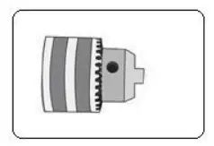
There are three types of rotary attachments: large, small, and three-jaw rotary attachments, as follows:
Can hold cylinders with a diameter of 5~20 millimeters
Can hold cylinders with a diameter of 8~100 millimeters
Can hold cylinders with a diameter of 160~260 millimeters
1. This product is an advanced technology integrating optics, mechanics, and electronics. To ensure your safety and the device’s proper functioning, do not arbitrarily open the engraving machine’s back cover or alter the machine’s internal structure.
2. The engraving machine should be placed on a flat surface and should be kept stable to avoid tilting. Be careful to prevent collisions when moving the machine.
3. Connect the ventilation pipe of the exhaust fan or air purifier to the outside to maintain good ventilation.
4. Pay attention to keeping the inside of the engraving machine clean and dry. Accumulation of dust and moisture can significantly shorten the lifespan of the machine. Avoid using it in an excessively humid environment (relative humidity must be less than 80%); prevent water entrance or moisture exposure to the machine’s interior.
5. Before use, inspect the cooling water, data cables, and power lines. It is strictly forbidden to operate without cooling water to prevent the laser from burning out. The cooling water must be kept clean and pure. Hard water scale and debris in dirty water can block the pipes and the laser, affecting the engraving effect, and even cause explosions.
If scale deposits are found in the laser, they should be treated immediately. You can add some hydrochloric acid (about 10%) to the circulating water, run the pump for about 20 minutes, and once the scale in the glass pipe is observed to dissolve, replace with clean water to remove the deposits.
6. The exhaust dust removal system tends to accumulate smoke and dust. If not cleaned timely, it can get blocked. It should be cleaned at least once a week. During cleaning, first remove the exhaust pipe, pour out the dust inside, then wipe the exhaust fan blades and air intake clean with a damp cloth.
7. Both the reflection mirror and the focus mirror are consumable items. If not maintained in a timely manner, the smoke and dust produced by the engraving process can corrode the mirror surface coating.
A damaged coating cannot fully reflect or transmit the laser; instead, it absorbs the heat generated by the laser, which not only affects the engraving effect but can also cause the mirror to shatter. The specific method for mirror maintenance is as follows:
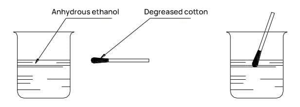

Inspect the reflective mirrors, which are surface-coated with a gold film. When cleaned properly, they should display a uniform gold color. If any spots or traces are present, gently wipe them off with a degreasing cotton swab dipped in anhydrous ethanol, as shown in Figure 5-1.
When cleaning the focusing lens, unscrew the lens cap, remove the lens, clean it using a degreasing cotton swab soaked in anhydrous ethanol, and then reinsert it into the laser head’s focusing lens tube as it was.
If any damage to the coating is detected, the reflective mirrors and focusing lens should be replaced promptly. To change the lens, first unscrew the lens cap, remove the old lens, insert the new lens into the lens cap, and then screw it back in place.
The brighter side of the reflective mirror is the working face and should be aligned with the light path. When installing the focusing lens, ensure the convex side is facing downward. After lens replacement, the light path and focal length may slightly change; please adjust them accordingly. Refer to Section 2.5 for the light path adjustment method.
Note: The lens is made from fragile glass; handle it with care during cleaning and replacement.
8. The laser is a consumable item. Over time, its internal gases will be consumed, and its power will subsequently decrease; this is normal. When you notice a significant decrease in engraving depth under the same parameters, you may consider increasing the output current. If after a while, even the maximum current cannot meet the engraving requirements, consider replacing the laser.
9. The engraving machine is a precision instrument with high requirements for light path adjustment. If the laser’s light path is off, the engraving effect will be impacted. If you notice any light path deviation during engraving, adjust it promptly. Refer to Section 2.5 for the specific adjustment method.
10. Prior to processing new materials, determine whether the material is suitable for laser engraving, and establish engraving parameters through experimentation.
11. It is strictly forbidden to insert any part of the body into the light path to prevent burns.
12. The laser, focusing lens, and reflective mirrors are consumable items and are not covered by the warranty. Please maintain them carefully. If replacements are needed, please purchase them at the listed price.
| Serial Number | Fault Symptoms | Solution Methods |
| 1 | After data output, the engraving machine ceases to function. | Turn off the power and verify that the power and data cables of the engraving machine are properly connected. |
| 2 | The laser isn’t emitting light. | Ensure the high-pressure switch has been activated. |
| Inspect the “current adjustment” knob to ensure it’s set to zero (rotated fully counterclockwise, at which point the laser should be in a non-emitting state). If it is, please adjust it to an appropriate position. | ||
| Observe if the cooling water system is functioning properly. If the cooling water does not circulate or the circulation volume is too small, immediately shut down the machine and inspect the circulation system. There are generally two common scenarios: ☆ The submersible pump stops working. In this case, check the power supply of the pump. If the power supply is normal, it indicates that the pump has malfunctioned and needs to be replaced. The submersible pump used in the C series engraving machines requires a head of over 3m and a flow rate of more than 3000L/h. ☆ The submersible pump is in good condition. At this point, it’s necessary to check whether the water pipes and the inlet and outlet of the laser are unobstructed. If blockage or leakage is found, it must be immediately addressed. Extra caution is required when cleaning the laser’s inlet and outlet to avoid damaging the glass shell. Note: The pump can be restarted for circulating cooling only when the temperature of the laser has 2dropped to room temperature. | ||
| If the power of the laser has been gradually diminishing prior to this, it could signify the end of its lifespan, and it should be promptly replaced. | ||
| 3 | Upon inspection, despite the laser operating normally and the processing parameters being accurate, the machining results are subpar. | Inspect whether the processing plane is on the focal plane of the focusing lens. |
| Determine if the power of the laser has started to diminish. If this is the case, consider appropriately increasing the output current or contemplate replacing the laser. | ||
| Examine if the optical path is deflected, refer to section 3.2.4 for the methods of adjusting the optical path. | ||
| 4 | Excess lines appear during the machining process. | Inspect the data cable and replace it with a new one if necessary. |
| Check the grounding condition of both the engraving machine chassis and the computer chassis, ensuring that the ground wire connections are functioning correctly. | ||
| 5 | During cutting, the lines display a serrated pattern. | Decrease the cutting speed during the setup of cutting parameters to enhance the quality of the cut. |
| 6 | During processing, only a portion of the design was output. | The issue may have occurred due to the layout exceeding the boundaries during formatting. It should be resolved by moving the graphics within the layout interface in the editing software. |
Caution: This product is a high-tech integration of optical, mechanical, and electrical systems. To ensure your safety and the normal operation of the equipment, do not arbitrarily open the engraving machine’s electrical control box or alter its internal structure.
1. Under normal usage, this engraving machine comes with a one-year warranty.
2. All consumables are not covered by the warranty. This includes lasers, mirrors, and focusing lenses.
3. Fees for consumables: Charges are based on the company’s unified maintenance fee standards.
4. Daily maintenance of software and equipment covered by training is not included in the warranty.
This product is a high-tech integration of optics, mechanics, and electronics. To ensure your safe use and the normal operation of the equipment, please observe the following:
1. Do not arbitrarily open the back cover of the engraving machine or alter its internal structure.
2. Avoid subjecting the equipment to strong vibrations or tilting it.
3. Avoid using the equipment in overly humid environments; prevent water intrusion or dampness.
4. Please clean the internal lenses timely (strictly follow the cleaning procedures outlined in this manual).
5. During operation, ensure good circulation of cooling water and maintain its quality. Clean promptly if scale is found to prevent overheating or even bursting of the laser.
6. Prevent damage to the laser’s exterior due to reasons such as freezing of cooling water, scale or dirt blockage, mechanical impact, etc.
7. The worktable and other components should be cleaned regularly.
8. Prevent the chassis from corroding and damaging electronic components due to excessive accumulation of smoke and humidity.
9. For other precautions and maintenance points, please refer to the precautions and maintenance points in the product manual.
Step One: Ensure the equipment is in a dry, pollution-free, and vibration-free environment.
The engraving machine operates under high voltage. Excessive humidity can cause high-voltage discharge, damaging the motherboard and power supply. Thus, engraving in overly humid environments is strictly prohibited!
Step Two: Check the working voltage.
The equipment’s working voltage is AC220V±10V, 50HZ. If the grid voltage is unstable, a voltage stabilizer should be installed.
Step Three: Install the laser, connect the circulating cooling water, and the dust extraction ventilation system.
The glass tube laser heats up during operation. If not cooled in time, the laser will break and damage. Additionally, high water temperature will affect the normal light output of the laser. Do not power on before properly connecting the cooling water!
If tap water is hard, replace it with pure water to prevent scale deposition and blockage in the laser.
Step Four: Connect the power cord, printer cord, and ground wire.
An overly dry environment or air conditioning can cause static electricity to accumulate on the surface of the chassis. Poor grounding can cause data transmission errors, affecting the engraving results and potentially causing other safety incidents.
Step Five: Adjust the optical path.
Laser engraving machines are precision optical instruments. They demand high requirements for optical path adjustments. If the laser does not enter from the center of each mirror, it will affect the engraving results. It’s recommended that users always check the optical path before starting work. (For operation method, refer to 2.5)
Note: Only professionally trained operators should perform the work of adjusting the optical path.
Step Six: Install printer drivers, USB dongle drivers, and ACE software.
Make sure to set the printer driver preferences to this machine model. (For operation method, refer to the printer driver system user manual)
Step Seven: Graphic editing.
Enter the ACE engraving software. Use the various features of the ACE software to arrange the engraving and cutting content. You can also use the software to load *.Bmp or *.Plt files made in advance into the ACE software. (For operation method, refer to the ACE software manual)
Step Eight: Positioning for processing.
After the layout is complete, you need to first determine the processing position before placing the processing materials. (For operation method, refer to the ACE software manual)
Step Nine: Determine processing parameters.
Processing parameters include interval, speed, and current. Before processing, you need to set the processing parameters according to the properties of the material and processing requirements. This usually requires experimentation. (For operation method, refer to 3.2)
Step Ten: Place the processing materials, adjust the focal length.
Ensure the “Manual Light Output” is not pressed, then adjust the focus. (For operation method, refer to 2.6)
Step Eleven: Output data for processing.
After placing the processing materials, generate and output data in the computer, and the engraving machine begins processing. (For operation method, refer to the ACE software manual)
Note: Before outputting data, make sure the “High Voltage Switch” is pressed, but do not press “Manual Light Output”.
Step Twelve: Completion of processing.
Upon completion of processing, there will be an audible alert. During the processing, ensure the cooling water circulates normally.
After processing, please clean the workbench and keep the engraving machine clean.

As the founder of MachineMFG, I have dedicated over a decade of my career to the metalworking industry. My extensive experience has allowed me to become an expert in the fields of sheet metal fabrication, machining, mechanical engineering, and machine tools for metals. I am constantly thinking, reading, and writing about these subjects, constantly striving to stay at the forefront of my field. Let my knowledge and expertise be an asset to your business.