Angle Measurement Using a Theodolite: Expert Guide
Have you ever wondered how surveyors measure precise angles on construction sites? This article explores the use of theodolites, advanced instruments designed for accurate angle measurements in surveying and engineering. By understanding their principles, structure, and methods, you’ll learn how these tools ensure accuracy in mapping and building. Discover the components and techniques that make theodolites essential for professionals in the field. Dive in to grasp how these devices work and improve your knowledge of precise angle measurement.
Section 1: Principle of Horizontal Angle Measurement
I. Concept of a Horizontal Angle
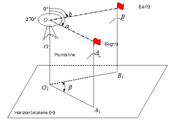
The angle formed by the perpendicular projection onto a horizontal plane of two directional lines intersecting at a point is known as a horizontal angle. It is usually represented by β, with an angle range of 0˚ to 360˚.
As shown in Figure 3-1, A, O, and B are arbitrary points on the ground. The horizontal angle between directional lines OA and OB is the angle formed by the perpendicular projections O1A1 and O1B1 of OA and OB onto the horizontal plane H. This angle is represented by β.
II. Principle of Horizontal Angle Measurement
As shown in Figure 3-1, a graduated circle is horizontally placed at any height above point O. The center of the circle coincides with the plumb line passing through point O. Two vertical planes are established through OA and OB respectively, and the readings intercepted by these two vertical planes on the graduated circle are denoted as a and b. The value of the horizontal angle β can be calculated as follows:
(3-1)
Instruments used to measure horizontal angles must have a level disk that can be placed in a horizontal position, and the center of the level disk should coincide with the plumb line passing through the vertex of the horizontal angle.
The telescope on the instrument not only rotates in the horizontal plane but also in the vertical plane. The theodolite is designed and manufactured according to the above basic requirements for measuring angles.
Section 2: Structure of Optical Theodolite
Optical theodolites are classified into different levels based on their measuring accuracy, such as DJ07, DJ1, DJ2, DJ6, and DJ15. “DJ” represents the first letter in the Chinese pinyin for “geodetic surveying” and “theodolite,” respectively, while the subscripts 07, 1, 2, 6, and 15 indicate the instrument’s precision level, which is expressed as “the standard deviation of the direction observation error for one measurement in seconds.”
I. Structure of DJ6 Optical Theodolite
The DJ6 optical theodolite mainly consists of three parts: the sighting system, level disk, and base.
1. Sighting System
The sighting system refers to the part above the level disk that can rotate around its axis. The sighting system is mainly composed of a vertical axis, telescope, vertical disk, reading device, leveling tube, and optical collimator.
(1) Vertical Axis: The rotation axis of the sighting system is called the vertical axis of the instrument. By adjusting the locking screw and fine adjustment screw, the rotation of the sighting system in the horizontal direction can be controlled.
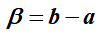
(2) Telescope: The telescope is used to sight the target. In addition, to facilitate accurate targeting, the crosshairs of the theodolite’s reticle plate are slightly different from those of the level. See Figure 3-3 for details.
Figure 3-3: Crosshair Graduation Plate of Theodolite.
The rotation axis of the telescope is called the horizontal axis. By adjusting the locking screw and fine adjustment screw of the telescope, its up-and-down rotation can be controlled.
The line of sight of the telescope is perpendicular to the horizontal axis, and the horizontal axis is perpendicular to the vertical axis of the instrument. Therefore, when the vertical axis of the instrument is vertical, the telescope rotates around the horizontal axis to sweep out a vertical plane.
(3) Vertical Disk: The vertical disk is used to measure vertical angles and is fixed at one end of the horizontal axis and rotates with the telescope.
(4) Reading Device: The reading device is used to read the readings from the level disk and the vertical disk.
(5) Leveling Tube: The leveling tube of the sighting system is used to accurately level the instrument. The axis of the leveling tube is perpendicular to the vertical axis of the instrument. When the bubble of the leveling tube is centered, the vertical axis of the theodolite is vertical, and the level disk is in a horizontal position.
(6) Optical Collimator: The optical collimator is used to make the center of the level disk coincide with the plumb line passing through the station point.
2. Level Disk
The level disk is used to measure horizontal angles. It is a circular ring made of optical glass with graduations of 0° to 360° marked on it. The full-degree graduations are labeled with annotations and the values of the graduations are either 1° or 30′, labeled in clockwise order.
The level disk is separate from the sighting system, and it does not rotate with the sighting system when it is moved. If it is necessary to change the position of the level disk, the level disk changing handwheel on the sighting system can be used to move the disk to the desired position.
3. Base
The base is used to support the entire instrument and fix the theodolite to the tripod via a center connection screw. There are three foot screws on the base for leveling the instrument. In addition, there is a fixing screw socket on the base used to control the connection between the sighting system and the base.
II. Reading Device and Methods
When the reading on the level disk is less than the graduation value, a micrometer is used to read the reading. The DJ6 optical theodolite generally uses a vernier micrometer.
As shown in Figure 3-4, there are two reading windows visible through the reading microscope: the window with “Horizontal” or “H” is for the reading of the level disk, and the window with “Vertical” or “V” is for the reading of the vertical disk. Each reading window has a vernier scale.
Figure 3-4 Reading of Micrometer Scale.
The length of the vernier scale is equal to the width of the 1° image on the level disk. The entire length of the vernier scale represents 1°. The vernier scale is divided into 60 small divisions, with each small division representing 1′, which can be estimated to 0.1′ or 6″. Every 10 small divisions are marked with a number indicating multiples of 10′.
To take a reading, first adjust the eyepiece of the reading microscope to focus on the graduation line in the reading window and make sure it is clear.
Next, read the degree value indicated by the graduation line on the vernier scale, and finally, read the fractional part less than 1° on the vernier scale using the graduation line as a reference while estimating the number of seconds.
As shown in Figure 3-4, the reading on the level disk is 164°06′36″, and the reading on the vertical disk is 86°51′36″.
III. Introduction to the Structure of DJ2 Optical Theodolite
1. Features of DJ2 Optical Theodolite
Compared with DJ6 optical theodolite, DJ2 optical theodolite has the following features:
(1) The structure between the axes is stable, and the magnification of the telescope is larger, and the sensitivity of the leveling tube in the sighting system is higher.
(2) In the reading microscope of the DJ2 optical theodolite, only one image of either the level disk or the vertical disk can be seen. When taking a reading, the image of the disk that needs to be read is brought into view by rotating the image conversion handwheel.
(3) DJ2 optical theodolite uses a contra-parallactic reading device, which is equivalent to obtaining the average value of two readings at 180° apart on the disk, thus eliminating the influence of eccentricity errors and improving reading accuracy.
2. Reading Method of DJ2 Optical Theodolite
The contra-parallactic reading device reflects the graduations on the disk relative to the line 180° away from them simultaneously into the reading microscope through a series of prisms and lenses, and they appear on a horizontal line above and below the middle point, as shown in Figure 3-6.
The window in the lower right corner shows the coincidence of the graduation lines. The number above the reading window on the upper right is the degree value, the number in the small box protruding in the center is the multiple of 10′, and the reading window in the lower left is for the micrometer.
Figure 3-8 Reading of DJ2 Optical Theodolite.
The micrometer scale is divided into 600 small divisions, with each division representing 1″. The range of the micrometer scale is 10′, and it can be estimated to 0.1″. The number on the left side of the reading window in the micrometer is the minute value, and the number on the right side is the multiple of 10″. The reading method is as follows:
(1) Rotate the micrometer wheel to make the graduation lines in the coincidence window precisely coincide, as shown in Figure 3-6b.
(2) Read the degree value in the reading window.
(3) Read the multiple of 10′ in the small box protruding in the center.
(4) Based on the position of the single index line in the micrometer reading window, directly read the fractional part less than 10′ and the seconds while estimating to 0.1″.
(5) Add up the degree value, the multiple of 10′, and the reading on the micrometer scale to obtain the reading of the disk. The reading in Figure 3-6b is:
As the founder of MachineMFG, I have dedicated over a decade of my career to the metalworking industry. My extensive experience has allowed me to become an expert in the fields of sheet metal fabrication, machining, mechanical engineering, and machine tools for metals. I am constantly thinking, reading, and writing about these subjects, constantly striving to stay at the forefront of my field. Let my knowledge and expertise be an asset to your business.
Imagine knowing exactly how much stress your metal components can handle without cutting them open. X-ray residual stress measurement offers this insight by using non-destructive testing methods. This article explores…
How do you measure the straightness of a guide rail to ensure precise machine operations? This article explores two common methods: the two-end point connection method and the minimum condition…
Have you ever wondered how the tiniest measurement can impact the quality of a machine? This article dives into the fascinating world of mechanical measurement, revealing how precision in dimensions,…
How do you measure the intricate curves and grooves of a complex workpiece? Standard tools fall short, making precise measurement difficult. This article delves into specialized instruments designed for these…
Imagine a world where machines can see, feel, and respond to their surroundings with unparalleled precision. This is the promise of novel sensing technologies in mechanical engineering. By integrating advanced…
Attention all mechanical engineers and manufacturing professionals! Are you struggling with pesky anodizing defects in your aluminum products? Look no further! In this blog post, we'll dive deep into the…
Have you ever wondered what makes a perfect circle? In the world of mechanical engineering, roundness is a crucial concept that affects the performance and longevity of rotating components. This…
Have you ever wondered what makes sheet metal so versatile in engineering? This article explores the fascinating world of sheet metal, diving into its material properties, manufacturing processes, and design…
Have you ever wondered what those mysterious numbers on a metal part mean? In this blog post, we'll dive into the fascinating world of hardness testing and explore the different…