The Concept of 5-Axis Machining
5-Axis Machine Fundamentals
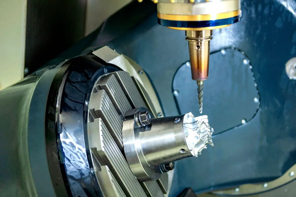
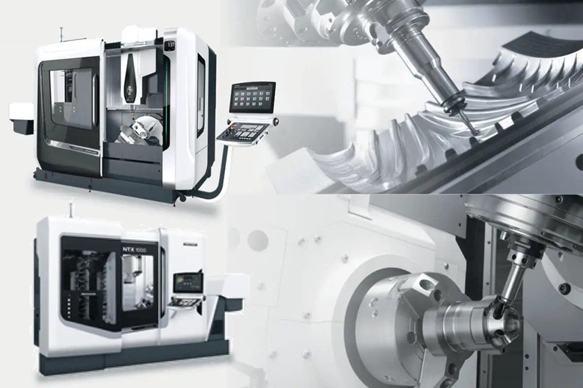
5-axis machining refers to the use of CNC systems to simultaneously move cutting tools or workpieces along five different axes. These machines enable the cutting tool to approach the workpiece from nearly any direction, resulting in more accurate and complex parts.
The five axes of movement are:
- X-axis: left and right along the table
- Y-axis: front and back along the table
- Z-axis: up and down perpendicular to the table
- A-axis: rotation around the X-axis
- B-axis: rotation around the Y-axis
By incorporating rotations along the A and B axes, 5-axis machines achieve higher levels of precision and allow for the creation of more intricate shapes. This added flexibility can reduce setup times, improve surface quality, and produce parts with tighter tolerances.
Simultaneous 5-Axis Machining
Simultaneous 5-axis machining is a specific method that involves moving all five axes at the same time during the machining process. Unlike traditional 3-axis or indexed 5-axis machining methods, simultaneous 5-axis machining offers continuous multi-axis movement, resulting in a smooth and continuous cutting path.
This approach enables even more complex part geometries and tighter tolerances by controlling the angular position of the cutting tool in relation to the workpiece at all times. Simultaneous 5-axis machining significantly reduces the risk of tool collisions, eliminates the need for multiple setups, and enables shorter and more rigid tooling, which reduces vibrations and leads to improved surface finishes.
In summary, 5-axis machining provides numerous benefits, such as increased accuracy, flexibility, and efficiency. The inclusion of simultaneous 5-axis machining techniques pushes the boundaries even further, allowing manufacturers to produce more complex and intricate parts with higher levels of precision.
5-Axis Machining Processes
Cutting Processes
5-Axis machining involves cutting processes that utilize multi-directional movements, which enable greater flexibility and precision. Cutting tools are operated in five axes instead of the traditional three, which includes not only linear movements along the X, Y, and Z-axes, but also rotation around A and B-axes. This increased freedom of movement allows for complex geometries to be machined more efficiently and accurately.
Important aspects of cutting processes in 5-axis machining include:
- Tool-path optimization: This reduces machining time and improves tool life by avoiding unnecessary movements.
- Continuous cutting: By adjusting the tool orientation continuously, better surface quality can be achieved and tool life extended.
- Collision avoidance: The advanced software ensures that the cutting tool and the workpiece do not collide, minimizing potential damage to the machine or the part being machined.
Milling Processes
Milling processes in 5-axis machining centers include various techniques that enable the creation of intricate and precise geometries. These processes are often carried out using Computer Numerical Controlled (CNC) machines, which ensure high levels of accuracy, repeatability, and efficiency. Some of the most common milling processes in 5-axis machining include:
- Contour milling: This process involves cutting along the desired geometric path, creating smooth surfaces and reducing the need for post-process finishing.
- Indexed milling: It allows the cutting tool to be positioned at specific intervals, enabling machining of complex geometries with high precision.
- Simultaneous 5-axis milling: In this process, the cutting tool and the workpiece are both moved simultaneously, which enables the milling of complex and detailed parts.
Machining Setups
The complexity of 5-axis machining requires advanced setups to ensure that the workpiece is accurately positioned and held securely during the processes. There are several types of setups commonly used in 5-axis machining centers, including:
- 3+2 axis configuration: This setup involves positioning the workpiece in a stationary manner while the cutting tool moves along the desired axes. Although it is not a true 5-axis configuration, it provides adequate flexibility for most applications.
- Swivel head configuration: In this setup, the cutting tool can be rotated around the A and B-axes, which allows for a wider range of geometries to be machined.
- Trunnion table setup: This configuration features a rotating table that holds the workpiece, enabling better access to its various surfaces by the cutting tool.
Choosing the right setup for a specific machining operation depends on various factors, such as the complexity of the part, available equipment, and desired level of precision. Proper setup selection can greatly impact the quality of the finished product, as well as reduce machining time and resource utilization.
5-axis Machining
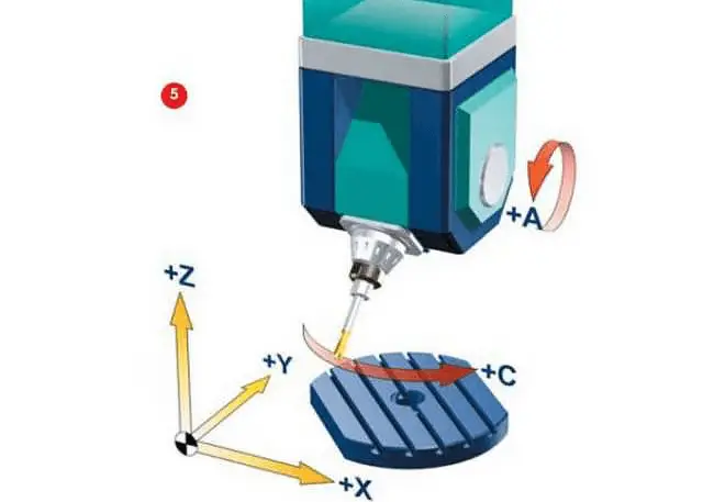
To truly understand 5-axis machining, we first need to understand what a 5-axis machine tool is. 5-axis machining, as the name suggests, involves the addition of two rotary axes to the three common linear axes of X, Y, and Z.
The two rotating axes (A, B, and C axis) have different motion modes to meet the technical requirements of various products.
Machine tool manufacturers continuously strive to develop new motion modes to meet various requirements in the mechanical design of 5-axis machining tools.
In conclusion, there are various types of 5-axis machine tools currently available in the market. Although their mechanical structures vary, the main forms include:
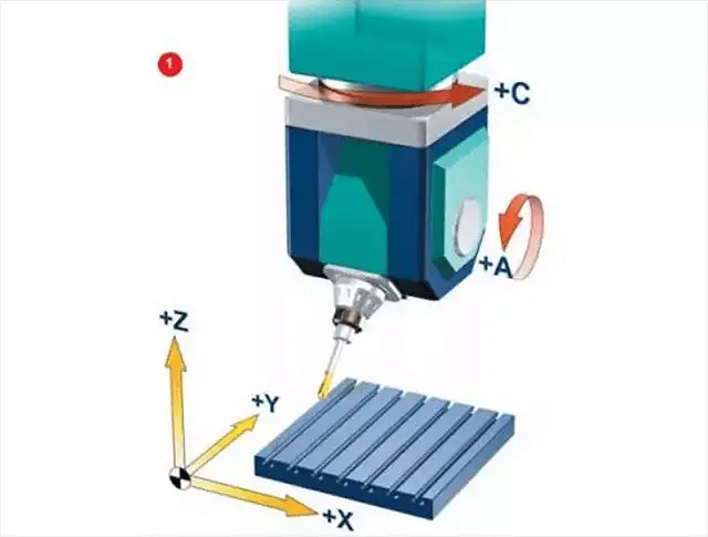
Two rotating coordinates directly control the direction of the tool axis (Double pendulum head form)
The two coordinate axis are at the top of the tool, but the rotation axis is not perpendicular to the linear axis (Nutate swing head form)
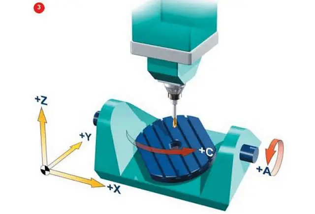
Two rotating coordinates directly control the rotation of the space (Double turntable form)
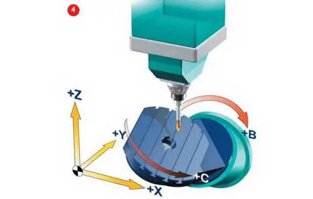
The two coordinate axis are on the worktable, but the rotation axis is not perpendicular to the linear axis (Nutate workbench form)
Two rotating coordinates, one acting on the tool and the other acting on the workpiece (one swing and one rotation form)
*Terms: If the axis of rotation is not perpendicular to the linear axis, it is considered a “nutate form” axis.
Having understood the 5-axis machine tools, we should now delve into their movements.
However, with such a diverse array of machine tool structures, what unique properties can they display during machining?
In comparison to traditional 3-axis machine tools, what are the benefits?
Let us now examine the highlights of the 5-axis machine tool.
Features of 5-axis Machine Tools
Speaking of the characteristics of 5-axis machine tools, it’s important to compare them with traditional 3-axis machines.
3-axis processing equipment is more common in production, and there are several forms such as vertical, horizontal, and gantry.
The common processing methods include end cutting and side cutting with an end milling cutter, and profiling processing with a ball nose cutter, among others.
However, no matter the form or method, one common feature is that the direction of the tool axis remains unchanged during the machining process.
The machine tool can only realize movement of the tool in the spatial rectangular coordinate system through interpolation of the three linear axes X, Y, and Z.
Therefore, when faced with certain products, the disadvantages of the 3-axis machine tool are exposed, such as low efficiency, poor surface quality, and even an inability to process the product.
Compared with 3-axis CNC machining equipment, 5-axis machining centers offer the following benefits:
- Maintain the best cutting state of the tool and improve the cutting conditions
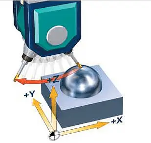
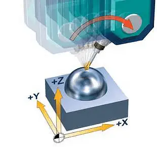
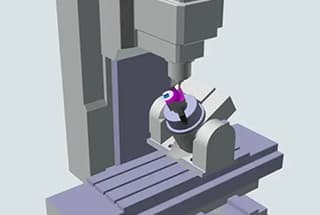
As shown in the figure, in the 3-axis cutting mode on the left, when the cutting tool moves to the tip or edge of the workpiece, the cutting conditions gradually deteriorate.
To maintain the best cutting state, the table must be rotated.
To fully process an irregular plane, the worktable must be rotated multiple times in different directions.
It can be seen that the five-axis machine tool can also prevent the situation where the linear velocity of the center point of the ball end mill is zero, resulting in a better surface quality.
- Effectively avoid tool interference
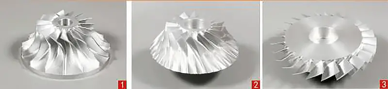
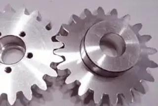
As shown in the figure above, for the aerospace field components such as impellers, blades, and blisks, the 3-axis equipment fails to fulfill the processing requirements due to interference.
The 5-axis machining tool can meet this requirement.
Additionally, the 5-axis machine tool can also employ shorter tools for processing, which enhances the rigidity of the system, reduces the number of tools required, and eliminates the need for special tools.
For business owners, this translates to cost savings in terms of tool expenses with the use of 5-axis machine tools.
- Reduce the number of clamping and complete five-sided processing in one clamping
As can be seen from the above figure, the 5-axis machining center can also reduce bench conversion and improve machining accuracy.
In actual processing, only one clamping is required, making it easier to guarantee accuracy.
Moreover, due to the shortening of the processing chain and the reduction in the number of equipment for the 5-axis machining center, the number of fixtures, workshop area, and maintenance costs have also been reduced.
This means you can use fewer fixtures, less workshop space, and incur lower maintenance costs to achieve more efficient and higher-quality processing!
- Improve processing quality and efficiency
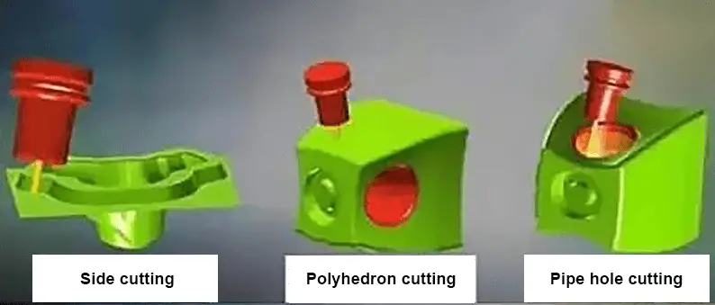
As demonstrated in the figure, the 5-axis machine tool can perform cutting through the side edge of the tool, resulting in improved processing efficiency.
- Shorten the production process chain and simplify production management
The complete machining capability of the 5-axis CNC machine tool significantly shortens the production process and streamlines production management and planning.
Its advantages become increasingly apparent for more complex workpieces compared to traditional methods with dispersed processes.
- Shorten the new product development cycle
For companies in the aerospace and automotive industries, the development of new products often involves complex shapes and high precision requirements.
In these cases, the use of a 5-axis CNC machining center, with its high flexibility, precision, and complete processing capabilities, can effectively address the accuracy and cycle problems in the processing of complex parts.
This, in turn, significantly reduces the development cycle and improves the success rate of new product development.
It’s important to note, however, that 5-axis machines are more complex than their 3-axis counterparts, with regards to tool attitude control, CNC, CAM programming, and post-processing.
Additionally, there are true and false 5-axis issues to consider. The distinction between true and false 5-axis lies in the presence or absence of the RTCP function.
To better understand RTCP and how it’s produced and applied, let’s dive into the machine tool structure and programming post-processing.
About RTCP
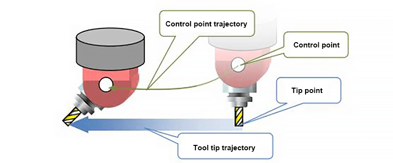
RTCP, which stands for Rotated Tool Center Point, is a crucial aspect of high-grade 5-axis CNC systems. It is also known as the tooltip follow function.
In 5-axis machining, the rotary motion of the tool produces additional movements of the tooltip, which affects the cusp locus and the attitude between the tool and the workpiece.
To ensure the tooltip follows the prescribed trajectory, the CNC system must automatically correct the control point, which often does not coincide with the tooltip.
The same technology may be referred to as TCPM, TCPC, or RPCP. These names are similar in meaning to RTCP, with the main difference being in the way the technology is applied.
RTCP specifically refers to the application of the pendulum head rotation center point to compensate in the double pendulum head structure.
On the other hand, functions like RPCP are mainly used on double rotary table machines to compensate for the change in linear axis coordinates caused by the rotation of the workpiece.
In essence, these functions aim to keep the center point of the tool and the actual contact point between the tool and the workpiece surface unchanged.
For the purpose of this article, such techniques will be referred to collectively as RTCP technology.
The Origin of the RTCP Function
Years ago, when five-axis machine tools were first becoming popular in the market, the RTCP concept was heavily hyped by machine tool manufacturers.
At that time, the RTCP function was more of a technology for technology’s sake and more of a marketing tool.
However, in reality, the RTCP function is not only a good technology, but also a valuable tool that can bring benefits and create value for customers.
With a machine tool equipped with RTCP technology (also known as a true 5-axis machine tool), operators do not have to carefully align the workpiece with the turntable axis.
Instead, they can simply clamp it and the machine tool will automatically compensate for the offset, which significantly reduces preparation time and improves machining accuracy.
Additionally, post-processing is easier because the tooltip coordinates and vectors are easily output.
As mentioned before, five-axis CNC machine tools mainly come in the form of double swing heads, double turntables, or one swing and one rotation structures.
In the following section, we will use a double turntable high-end 5-axis CNC system as an example to provide a detailed explanation of the RTCP function.
Defining the Fourth and Fifth Axes in a 5-axis Machine Tool:
In the double-rotating table structure, the rotation of the fourth axis affects the attitude of the fifth axis, and the fifth axis is the rotary coordinate on the fourth axis.
However, the rotation of the fifth axis does not affect the attitude of the fourth axis.
Ok, let’s explain after understanding the definition.
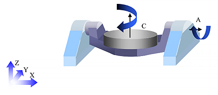
As depicted in the figure, the fourth axis of the machine tool is labeled as the A-axis and the fifth axis is the C-axis.
The workpiece is positioned on the C-axis turntable. When the 4th axis, the A-axis, rotates, the attitude of the C-axis will be impacted as it is installed on the A-axis.
When programming the tool center cutting for the workpiece placed on the turntable, any change in the rotation coordinate will result in a change in the X, Y, and Z coordinates of the linear axis, leading to a relative displacement.
To address this displacement, the machine tool must perform compensation, which is where the RTCP function comes into play.
So, how does the machine tool compensate for the offset?
To answer that, we need to first analyze the source of the offset. As previously discussed, the linear axis coordinate shift is caused by the change in the rotating coordinate. Hence, it is crucial to analyze the center of rotation of the rotating axis.
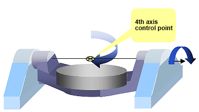
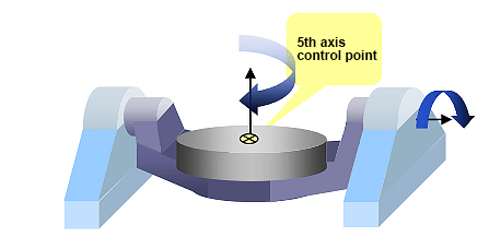
In a machine tool with a double turntable structure, the control point of the C-axis, or the fifth axis, is typically located at the center of rotation of the machine table.
The fourth axis usually chooses the midpoint of the fourth axis as its control point.
In order to achieve five-axis control, the CNC system must have knowledge of the relationship between the control points of the fourth and fifth axes.
In the initial state, when the A and C axes are at position 0, the fourth axis control point is the origin in the fourth axis rotation coordinate system and the fifth axis control point is represented by the position vector [U, V, W].
The CNC system also needs to be aware of the distance between the A and C axis.
For double turntable machine tools, an example can be seen in the accompanying figure.
It can be seen that for machines with RTCP capability, the control system is designed to keep the tool center always at the position specified in the programming. This means that programming is not affected by the machine’s movement.
When programming on the machine, you won’t need to consider machine movement or tool length. Simply focus on the relative movement between the tool and the workpiece. The job control system will handle the rest for you.
For example:
As illustrated in the figure, when the RTCP function is absent, the control system disregards the tool length.
As a result, the tool rotates around the center of its shaft, causing the tip to deviate from its position and become unfixed.
As demonstrated in the figure, when the RTCP function is activated, the control system only adjusts the direction of the tool, while the position of the tool tip remains constant.
The necessary compensations along the X, Y, and Z axes have been calculated automatically.
Regarding the issue of linear axis coordinate offset in 5-axis machine tools and CNC systems that lack RTCP, it is worth noting that many five-axis CNC machine tools and systems in China are considered “fake 5-axis”.
This term refers to machine tools without the RTCP function. It is not determined by appearance or whether the 5 axes are linked, as false five-axis can still be used for 5-axis linkage.
The main distinction between fake 5-axis is the absence of a real 5-axis RTCP algorithm, meaning that programming for fake 5-axis must account for the spindle’s swing length and the position of the rotating table.
This implies that when using fake five-axis CNC systems and machine tools in programming, it’s necessary to utilize CAM programming and post-processing technology to pre-plan the tool path.
If the machine tool or tool is altered for the same part, CAM programming and post-processing must be performed once again.
The fake 5-axis machine tool must also ensure that the workpiece is positioned at the center of rotation of the worktable when clamping.
This results in a considerable amount of time spent on clamping and aligning for the operator, and accuracy cannot be guaranteed.
Even for index processing, the fake 5-axis is problematic.
On the other hand, the true 5-axis only requires setting up one coordinate system and only one tool calibration to complete the machining process.
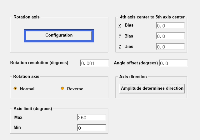
The following figure uses the NX post-processing editor settings as an illustration to demonstrate the coordinate transformation of the fake 5-axis.
As depicted in the figure, the fake 5-axis relies on post-processing technology to compensate for the displacement of the rotary axis to the linear axis coordinate by showing the center position relationship between the fourth and fifth axes of the machine tool.
The CNC programs generated for X, Y, and Z axis not only include approach points but also the necessary compensation on these axes.
This method leads to reduced processing accuracy, low efficiency, non-universal programs, and high labor costs.
Moreover, each machine tool has different rotation parameters, requiring a separate post-processing file, causing production inconvenience.
Fake five-axis programming cannot be altered and manual 5-axis programming is almost impossible.
The lack of RTCP function also limits its ability to use advanced derivative 5-axis functions, such as compensation.
In conclusion, the choice of 5-axis machine tool is not about true or false, but about the method used to achieve processing results. In terms of cost-effectiveness, true 5-axis machine tools are a more viable option.
Technologies in 5-Axis Machining
CNC Technology
5-axis CNC machining relies on computer numerical control (CNC) technology, which allows for precise machine movements and complex part production. This technology enables 5-axis machines to perform simultaneous movements along five different axes, enhancing the flexibility and efficiency of machining processes. CNC technology also reduces human intervention and the need for manual adjustments, resulting in improved repeatability and reduced errors.
Machining Accuracy
One of the key advantages of 5-axis machining is its high machining accuracy. These machines can achieve tight tolerances, often ranging from +/- 0.001 inches to +/- 0.0001 inches. This precision ensures that parts meet exact specifications, making it suitable for industries requiring complex geometries and high-quality finishes, such as aerospace, automotive, and medical device manufacturing. Enhanced accuracy also reduces the need for additional post-processing or finishing operations, minimizing production time and costs.
Tool Center Point
In 5-axis CNC machining, the Tool Center Point (TCP) is a critical aspect of the process. TCP refers to the point where the cutting tool meets the workpiece. During machining, the machine constantly adjusts the TCP to maintain contact with the workpiece while moving along the toolpath. This consistent, precise control of the tool’s position and orientation enables 5-axis machines to produce intricately shaped, curved, or angled components with a high level of precision. By accurately controlling the TCP, 5-axis machines can increase the overall quality of the final product while reducing the risk of costly errors and rework.
5-Axis Machining in Different Industries
Aerospace Industry
5-axis machining plays a critical role in the aerospace industry due to the need for precision and the complexity of the components used in aircraft and spacecraft. Complex shapes, such as turbine blades and airframes, require a high level of accuracy and surface finish that can be achieved with 5-axis machining. In addition, the aerospace industry often uses exotic materials like titanium and Inconel, which require advanced machining techniques for successful results.
Defense Industry
The defense industry relies heavily on 5-axis machining for the production of intricate parts and components used in military equipment. These components often require a high level of precision and durability to withstand harsh operating conditions. 5-axis machining is crucial for the production of:
- Weapon systems
- Missiles and guidance systems
- Military vehicles and aircraft components
The ability to machine complex shapes with a high degree of accuracy is essential for the functionality and performance of defense industry products.
Transportation Industry
5-axis machining has a significant impact on the transportation industry, particularly in the automotive and high-performance vehicle sectors. It enables the production of intricate and lightweight components that can improve fuel efficiency and vehicle performance. Some key applications in the transportation industry include:
- Engine components, such as pistons and cylinder heads
- Complex suspension and chassis parts
- Mold and die-making for body panels
The precision offered by 5-axis machining also ensures excellent surface finishes, reducing the need for additional finishing processes and improving the overall efficiency of the manufacturing process.
Materials and Tooling in 5-Axis Machining
Cutting Tools
In 5-axis machining, cutting tools are critical components for efficient and precise manufacturing. Various cutting tool materials are available to suit specific machining requirements. For example, carbide and high-speed steel (HSS) are popular choices for their durability and high-performance characteristics.
For machining aluminum and titanium, the ideal cutting tools should have excellent wear resistance and thermal stability. Polycrystalline diamond (PCD) and cubic boron nitride (CBN) tools are often preferred for these materials due to their properties. However, they may not be suitable for all workpieces, so it is essential to consider the intended application.
Another aspect to consider is the coating on the cutting tools, which can significantly enhance the tool’s performance by reducing friction and improving wear resistance. Common coatings include titanium nitride (TiN) and titanium aluminum nitride (TiAlN).
Material Profiling
When it comes to 5-axis machining, accurate material profiling is essential for delivering consistent results in complex shapes. One of the common applications of 5-axis machining is creating impellers, which require precise geometric profiling for optimal functioning.
- For aluminum, a lightweight and highly machinable material, 5-axis machining can deliver excellent surface finishes and intricate details. It is commonly used for parts in the aerospace and automotive industries due to its strength and corrosion resistance.
- In contrast, titanium is known for its high strength-to-weight ratio and excellent corrosion resistance, making it an ideal choice for aerospace and medical applications. However, titanium’s low thermal conductivity can cause heat buildup during machining, so proper cutting tools and cooling systems are essential to avoid premature wear.
In summary, the right combination of cutting tools and material profiling, along with appropriate knowledge of the workpiece material, is crucial to achieving successful outcomes in 5-axis machining. Careful consideration of these factors will ensure that even the most complex components can be produced with precision, efficiency, and reliability.
Quality and Productivity in 5-Axis Machining
Improving Surface Quality
5-axis machining offers many advantages when it comes to enhancing surface quality. First and foremost, this technique can produce complex parts with minimal setups, leading to a reduced risk of errors and ensuring higher part quality. Additionally, using continuous 5-axis motion allows for better management of the angle of the cutting tool. This ensures even wear, resulting in smoother surface finishes.
The use of probing systems plays a vital role in attaining excellent surface quality in 5-axis machining. It aids in monitoring the surface, identifying any discrepancies, and making necessary adjustments to improve accuracy. This, in turn, leads to better surface finishes and reduces scrap rates.
Boosting Productivity
In terms of productivity, 5-axis machining offers numerous benefits over traditional 3-axis machining:
- Shorter machining times: By incorporating simultaneous motion in all five axes, 5-axis machines can execute complex operations in a single setup. This reduces the time spent on setups and minimizes the overall machining process duration.
- Increased machine versatility: 5-axis machines handle different types of operations with ease, such as milling, drilling, and turning. This means a single machine can perform multiple functions, reducing the need for specialized machines or additional setups.
- Reduced tooling costs: The ability to maintain constant engagement with the workpiece in 5-axis machining means that tool wear is more evenly distributed. This prolongs tool life, lowering overall tooling expenses.
- Improved part quality: By utilizing 5-axis movement, machining can be performed closer to the part geometry without repositioning, which reduces the chance of errors and improves part quality.
In conclusion, 5-axis machining greatly enhances both the quality and productivity aspects of manufacturing processes. Through the use of advanced probing systems, versatile machines, and more efficient operations, 5-axis machining achieves higher surface quality and increased productivity in modern manufacturing.
Advancements and Trends in 5-Axis Machining
Innovation in Fixturing
In the world of 5-axis machining, advancements in fixturing have played a vital role in improving the production process. Fixturing refers to the system of holding, supporting, and positioning a workpiece while it is being machined. With the help of innovative fixturing systems, machinists can now work on complex shapes and surfaces more efficiently.
One notable innovation in fixturing is the integration of vacuum systems. This enables the workpiece to be held securely without traditional clamps, significantly improving access for the cutting tool. In addition, advancements in materials and design allow manufacturers to develop lighter, yet more robust, fixtures. This reduces setup time and facilitates faster production cycles.
Cutting Condition Trends
In 5-axis machining, cutting conditions greatly influence the quality of the final product. Over the years, machinists have identified key approaches to optimize the cutting process, enabling smoother and more accurate results.
Some cutting condition trends that are shaping the 5-axis machining industry include:
- Adaptive cutting strategies: These strategies take the load on the cutting tool into account and automatically adjust the cutting parameters. Such approaches reduce tool wear, minimize vibrations, and improve surface finishes.
- High-speed machining (HSM): This method involves running the cutting tool at higher speeds and feed rates while maintaining a smaller depth of cut. As a result, it improves productivity and enhances surface quality.
- Spline interpolation: Spline interpolation is a technique that allows for smoother transitions between tool paths during the cutting process. In 5-axis machining, this method helps to produce more precise and complex parts without sacrificing efficiency.
By incorporating these advancements and trends, 5-axis machining continues to push the boundaries of what is possible in the manufacturing of highly complex parts. Through innovation in fixturing and cutting condition trends, this field is unlocking new opportunities for efficiency and precision in modern manufacturing.