The Ultimate Guide to 6GR Welding
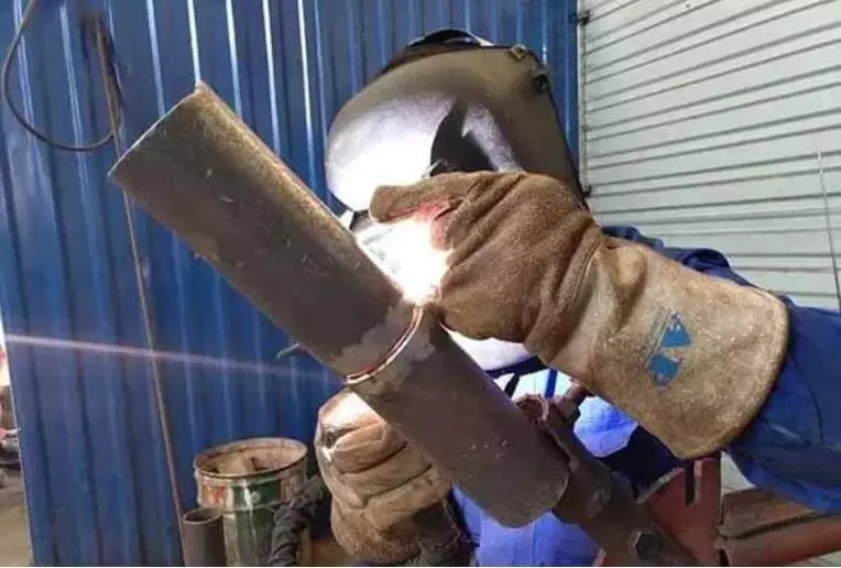
Ever wondered how welders achieve perfect joints in challenging positions? 6GR welding is a specialized technique for welding pipelines with an obstacle ring at a 45° angle, crucial for ensuring…
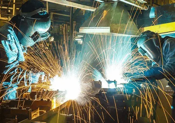
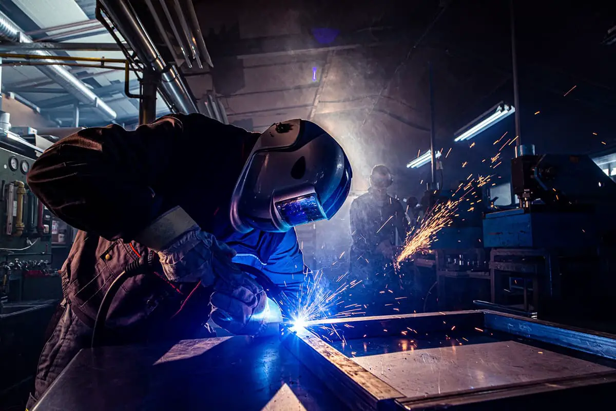
Have you ever wondered about the art of welding and the different positions involved? In this fascinating blog post, we’ll delve into the intricacies of welding positions, from flat to overhead, and explore their unique challenges and techniques. Our expert author, with years of experience in mechanical engineering, will guide you through the world of 1G, 2G, 3G, 4G, 5G, and 6G welding, providing valuable insights and practical knowledge. Get ready to expand your understanding of this essential skill in the realm of mechanical engineering!
The welding position refers to the relative placement of the workpiece to the welding equipment during the welding operation. There are four basic types of welding positions: flat, horizontal, vertical, and overhead. Each welding position has its specific operational requirements and precautions.
Flat position: This is the most common welding position, suitable for most welding scenarios. Welding performed in this position is called flat welding.
Horizontal position: This position is typically used when the weld seam needs to be observed or handled from the side. In horizontal welding, the selection of electrode angle and current is particularly important to ensure the quality of the weld seam.
Vertical position: Vertical welding involves placing the workpiece in an upright position for welding. This position is suitable for welding long, linear materials such as pipes. In vertical welding, the selection of the electrode and the adjustment of welding parameters are crucial to ensure welding quality.
Overhead position: Overhead welding is a position where the welding is done from underneath the weld seam, making it a challenging position as the operator needs to align the weld seam from above. During overhead welding, the welding current should be 10% – 15% less than during flat welding, and short arc operation should be used.
When choosing a welding position, factors such as the thickness of the weldment, the number of weld layers, and the type of joint need to be considered. For example, when welding high-power transistors, special attention may be needed to ensure proper insertion of the lead position, and the welding time should be minimized for better heat dissipation.
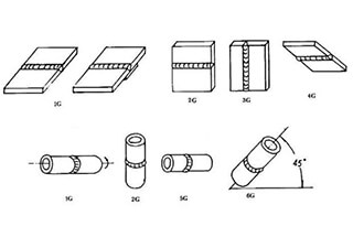
The positions of groove welds are classified as 1G, 2G, 3G, 4G, 5G, and 6G, respectively representing flat welding, horizontal welding, vertical welding, overhead welding, horizontal fixed welding of pipelines, and 45° inclined fixed welding of pipelines.
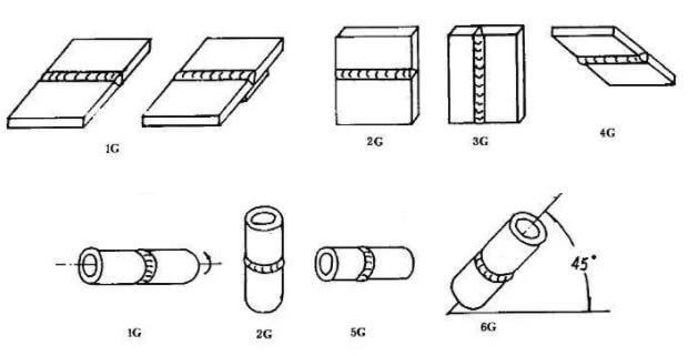
Plate fillet welds are classified as 1F, 2F, 3F, and 4F, representing ship-type welding, horizontal welding, vertical welding, and overhead welding, respectively.
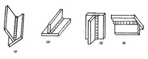
Tubesheet or tube fillet welds are classified as 1F, 2F, 2FR, 4F, and 5F, representing 45-degree rotary welding, transverse welding (with the tube axis vertical), horizontal rotary welding of the tube axis, and horizontal fixed overhead welding of the tube axis, respectively.

1G is flat welding
1G Welding characteristics:
Fusion welding of metal primarily relies on its own weight to flow into the molten pool.
The shape and composition of the molten pool are simple to maintain and control.
When welding metal with the same plate thickness, the welding current required for flat welding is higher compared to other welding positions, leading to higher production efficiency.
However, slag and the molten pool are prone to mixing, particularly when welding flat fillet welds, causing the slag to easily advance and form slag inclusions.
Acid electrodes can make it difficult to distinguish between the slag and molten pool, while alkaline electrodes provide clarity.
Incorrect welding parameters and techniques can result in defects such as bead formation, undercut, and welding deformation.
In single-side welding, if the back is free-forming, the first weld may exhibit issues such as uneven penetration or poor back formation.
Key points of 1G welding:
According to the thickness of the plate, a welding rod with a larger diameter and a higher welding current can be selected.
When welding, the electrode and the weldment should form an angle of 60-80°, and the separation of slag and liquid metal should be controlled to avoid slag leading.
For plate thicknesses of ≤6mm, a Type I groove should generally be used for butt flat welding, and a 3.2-4mm diameter electrode with a short arc welding technique should be used for the front weld, with penetration reaching 2/3 of the plate thickness.
Before back sealing, the root may not be cleaned, except for in important structures, but the slag should be cleaned, and the current can be higher.
If there is confusion between the slag and molten pool metal in butt flat welding, extend the arc, tilt the electrode forward, and push the slag behind the molten pool to prevent slag inclusion.
For horizontal and inclined welding, uphill welding should be used to avoid slag inclusion and to prevent the molten pool from moving forward.
When multi-layer, multi-pass welding is used, consider the number of welding passes and the welding sequence, with each layer not exceeding 4-5mm.
For T-joints, fillet, and lap flat angle welded joints, if the thickness of the two plates is different, the electrode angle should be adjusted to direct the arc to one side of the thicker plate to ensure even heating of the two plates.
Correct selection of strip transportation method
(1) For welding thickness less than or equal to 6mm, I-groove butt flat welding is used.
Double-sided welding should employ linear strip transportation for the front weld, at a slightly slow pace.
The back weld should also use linear strip transportation, with a slightly larger welding current and faster speed.
(2) For plate thickness less than or equal to 6mm, multi-layer welding or multi-layer multi-pass welding can be used when other groove forms are utilized.
The first layer of backing welding should use low current electrode, low standard current, and linear or serrated electrode welding.
When welding the filler layer, electrodes with larger diameter and short arc welding with higher welding current can be selected.
(3) For T-joint flat fillet welding with leg size less than 6mm, single-layer welding can be chosen and linear, oblique ring or sawtooth strip transportation methods can be used.
For larger welding leg size, multi-layer welding or multi-layer multi-pass welding should be used.
The linear strip transportation method is employed for backing welding, and inclined sawtooth or inclined ring strip transportation can be chosen for the filling layer.
(4) Multi-layer and multi-pass welding should generally use the linear strip welding method.
2G is horizontal welding
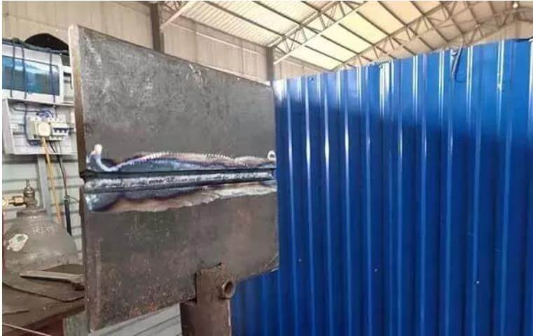
2G Welding characteristics:
The molten metal can easily drop into the groove due to its own weight, leading to undercut defects on the upper side and tear drop weld beading or incomplete penetration defects on the lower side.
The separation of molten metal and slag is relatively easy, similar to vertical welding.
Key points of 2G welding:
The V-type or K-type groove is generally used for butt horizontal welding, and for butt joints with a plate thickness of 3 to 4mm, both sides can be welded using type I groove.
A small diameter electrode should be selected and the welding current should be smaller than that used for flat welding. Short arc operation can better control the flow of molten metal.
For welding thick plates, multi-layer and multi-pass welding should be adopted in addition to backing welds.
When using multi-layer and multi-pass welding, special attention should be paid to controlling the overlapping distance between welding passes. Each overlap welding should start at 1/3 of the previous weld to prevent unevenness.
The appropriate electrode angle should be maintained according to the specific situation and the welding speed should be slightly blocked and uniform.
The correct strip transportation method should be used:
(1) For type I butt horizontal welding, the front weld is best done using the reciprocating linear strip transportation method.
For thicker parts, linear or small inclined annular strip should be used and linear strip should be used on the back. The welding current can be increased appropriately.
(2) For other groove butt horizontal welding, if the gap is small, straight-line strip transportation can be used for backing welding.
If the gap is large, the backing layer should use reciprocating linear strip transportation and other layers can use inclined ring strip transportation during multi-layer welding. Linear strip transportation should be used during multi-layer multi-pass welding.
3G is vertical welding

3G Welding characteristics:
The molten metal and slag separate easily due to gravity, which can result in defects such as weld beading, undercut, and slag inclusion.
The high temperature of the molten pool makes the metal flow downwards, leading to uneven welding.
Incomplete penetration can occur at the root of T-joint welds and it is easier to control the degree of penetration.
However, the productivity of welding is lower compared to flat welding.
Key points of 3G welding:
Maintain the correct electrode angle;
Vertical upward welding is commonly used in production and a specialized welding rod should be used for vertical downward welding to ensure quality.
The welding current for vertical upward welding is 10 to 15% less than that for flat welding, and a smaller electrode diameter (less than 4mm) should be selected.
Short-arc welding is used to reduce the distance from droplet transfer to the molten pool.
Adopt the correct strip transportation method.
(1) When vertically welding upward on a T-groove butt joint (commonly used for thin plates), the linear, serrated, and crescent strip transportation methods are commonly used. The maximum arc length should not exceed 6mm.
(2) For other forms of groove butt vertical welding, the first layer of welding often employs broken welding, crescent welding with a small swing, and triangular strip welding. Subsequent layers can be transported using a crescent or sawtooth shape.
(3) During vertical welding of T-joints, the electrode should have an appropriate dwelling time on both sides and top corners of the weld, and the swing amplitude of the electrode should not be larger than the width of the weld. The electrode transportation operation is similar to that of vertical welding of other groove forms.
(4) When welding the cover layer, the shape of the weld surface will depend on the strip transportation method. A crescent-shaped strip can be used if a slightly higher surface quality is required, while a sawtooth strip transportation method can be used for a flat surface (the middle concave shape is related to the pause time).
4G is overhead welding
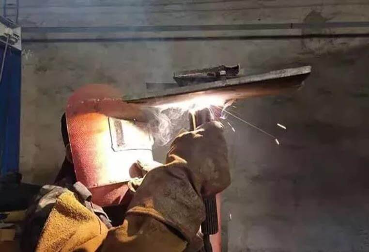
4G Welding characteristics:
Molten metal falls due to gravity, and the control of the shape and size of the molten pool is challenging.
The transportation of the strip is difficult, and a flat surface on the weldment is not easily achievable.
Defects such as slag inclusion, incomplete penetration, weld beading, and poor weld formation are commonly seen. The splashing and diffusion of molten weld metal can cause burn accidents.
Overhead welding is less efficient compared to other welding positions.
Key points of 4G welding:
For butt weld overhead welding, when the thickness of the weldment is ≤ 4mm, type I groove should be used, a 3.2mm electrode should be selected, and the welding current should be moderate.
When the weld thickness is ≥ 5mm, multi-layer and multi-pass welding should be used.
For overhead welding of T-joint welds, single-layer welding should be used when the weld leg is less than 8mm and multi-layer and multi-pass welding should be used when the weld leg is greater than 8mm.
The correct strip transportation method should be selected based on the specific situation:
(1) When the size of the welding leg is small, linear or linear reciprocating strip transportation should be used, and single-layer welding should be completed.
When the size of the welding leg is large, multi-layer welding or multi-layer and multi-pass welding strip transportation can be used.
The first layer should be transported using linear strip transportation, and subsequent layers can use inclined triangular or inclined ring strip transportation.
(2) No matter which strip transportation method is used, the amount of weld metal added to the molten pool at one time should not be excessive.
The horizontal fixing port of the pipeline is 5g position


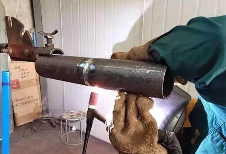
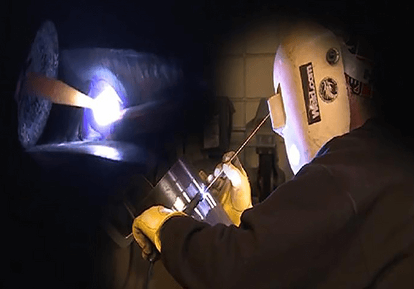
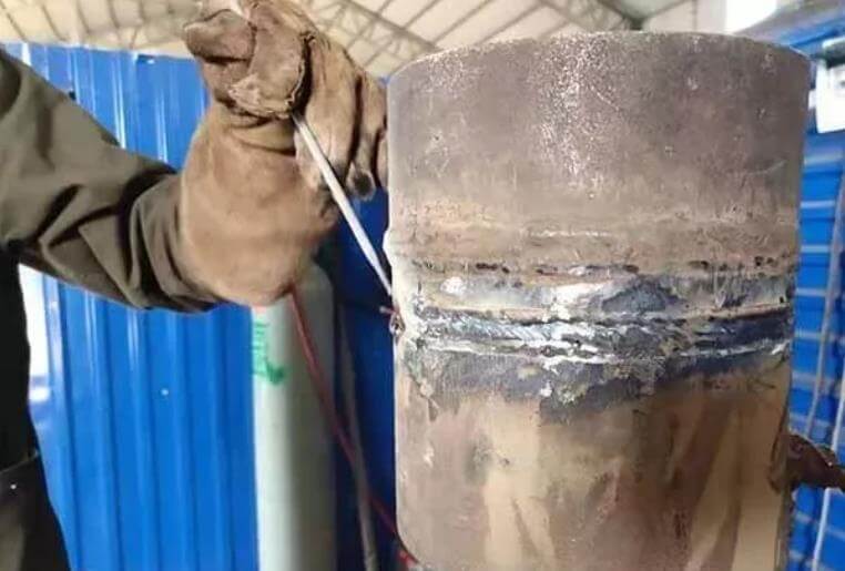
The 45 °oblique welded junction of the pipe is the 6G position
The selection of the welding position has a significant impact on the quality of welding. First, the welding position directly affects the stress and deformation of the weldment. If the welding position is chosen improperly, it can lead to excessive deformation or internal stress in the weldment. This not only reduces the quality of the weldment but can even result in the scrapping of the weldment in severe cases.
Moreover, different welding positions can affect the shape and location of the weld pool, especially when welding in vertical, horizontal, or overhead positions. Due to the effect of gravity, issues like undercutting can easily occur.
Therefore, arranging the position and the number of welds reasonably is one of the crucial measures to control welding deformation and improve welding quality.
The impact of the welding position selection on welding quality is mainly reflected in the following aspects:
Therefore, during welding operations, the appropriate welding position should be selected based on specific welding requirements, material characteristics, and structural rigidity, among other factors, to achieve the best welding results.
The advantages and disadvantages of vertical and overhead welding in practical applications are as follows:
Vertical welding’s strengths mainly lie in material conservation, weight reduction, simplicity of equipment, operational flexibility, and low cost. It’s particularly effective for irregular welds, short welds, overhead welds, high-altitude, and narrow-location welds, offering flexible application and effortless operation. The welding quality is high due to the high arc temperature, faster welding speed, and smaller heat-affected zone. The equilateral triangle running method is suitable for vertical welding of beveled butt joints and T-joints, able to produce thicker weld cross-sections in one go. It minimizes defects like slag inclusion, thus enhancing production efficiency.
The downside of vertical welding includes the fact that low current voltages are hardly used when welding from top to bottom during operation, resulting in poor strength. Although the formation is aesthetically pleasing, maintaining the correct electrode angle is essential.
The advantages of overhead welding include good process performance, easy arc initiation, stable arc, less spatter, good slag removal, aesthetically pleasing weld formation, easy mastery of welding technique, and good porosity resistance of acidic electrodes, with weld metal rarely causing issues.
The disadvantages of overhead welding are more conspicuous, mainly due to the tendency of molten metal to fall under gravity, making droplet transition and weld formation difficult. Additionally, the process performance of solid welding wire is poorer, making formation more challenging, and the absence of flux can also affect weld formation.
Vertical welding has clear advantages in terms of operational flexibility, cost-effectiveness, and adaptability to complex welds, but may face issues of insufficient strength in some cases. While overhead welding has its merits in terms of aesthetically pleasing weld formation and technical mastery, its main drawback is the increased welding difficulty due to the falling molten metal.
Each welding method can be performed using manual welding, mechanized welding, or automatic welding, with their codes as shown in the table below.
| Welding Method | Code |
| Stick Welding | SMAW |
| Gas Welding | OFW |
| Tig Welding | GTAW |
| Plasma Arc Welding | GMAW |
| Submerged Arc Welding | SAW |
| Electroslag Welding | ESW |
| Plasma Arc Welding | PAW |
| Gas Tungsten Arc Welding in the vertical position | EGW |
| Friction Welding | FRW |
| Stud Arc Welding | SW |
The forms, positions, and their codes of test pieces are shown in the table below. The test piece position basically determines the welding position.
Table 1. Test Piece Forms, Positions and Codes.
| Test Piece Form | Test Piece Position | Code | |
| Sheet metal butt-welding test piece | Flat welding test piece | 1G | |
| Horizontal welding test piece | 2G | ||
| Vertical welding test piece | 3G | ||
| Overhead welding test piece | 4G | ||
| Pipe butt-welding test piece | Horizontal rotation welding test piece | 1G (Rotation) | |
| Vertical fixed welding test piece | 2G | ||
| Horizontal fixed welding test piece | Upward welding | 5G | |
| Downward welding | 5GX(Downward) | ||
| 45°fixed welding test piece | Upward welding | 6G | |
| Downward welding | 6GX(Downward) | ||
| Pipe-to-plate corner joint test piece | Horizontal rotation welding test piece | 2FRG | |
| Vertical fixed flat welding test piece | 2FG | ||
| Vertical fixed overhead welding test piece | 4FG | ||
| Horizontal fixed welding test piece | 5FG | ||
| 45°fixed welding test piece | 6FG | ||
| Sheet metal corner welding test piece | Flat welding test piece | 1F | |
| Horizontal welding test piece | 2F | ||
| Vertical welding test piece | 3F | ||
| Overhead welding test piece | 4F | ||
| Pipe corner welding test piece (including pipe-to-plate corner welding test piece and pipe-to-pipe corner welding test piece). | 45°rotation welding test piece | 1F (Rotation) | |
| Vertical fixed horizontal welding test piece | 2F | ||
| Horizontal rotation welding test piece | 2FR | ||
| Vertical fixed overhead welding test piece | 4F | ||
| Horizontal fixed welding test piece | 5F | ||
| Threaded stud welding test piece | Flat welding test piece | 1S | |
| Horizontal welding test piece | 2S | ||
| Overhead welding test piece | 4S | ||
The sheet metal butt-welding test piece, pipe butt-welding test piece, and pipe-to-plate corner joint test piece can be divided into two types: with and without backing pads.
For double-sided fillet welds, groove welds, and pipe-to-plate corner joints where full penetration is not required, they are considered as with backing pads.
However, when single-sided welding is used with inert gas shielded welding, it cannot be considered as with backing pads.
(1) Sheet metal butt-welding test piece (when there is no groove, it is a fillet welding test piece).

(2) Sheet metal corner welding test piece.

Table 2. Applicable Welding Positions for Test Pieces
| Test Piece | Applicable Welding Range | ||||
| Butt Welding Position | Corner Welding Position | Pipe-to-plate corner joint welding position | |||
| Form | Code | sheet metal and pipes with an outer diameter greater than 600mm | pipes with an outer diameter smaller than or equal to 600mm | ||
| Sheet metal butt-welding (Note A-2) | 1G | Flat | Flat | Flat | / |
| 2G | Flat and horizontal | Flat and horizontal | Flat and horizontal | / | |
| 3G | Flat and vertical | Flat | Flat, horizontal and vertical | / | |
| 4G | Flat and overhead | Flat | Flat, horizontal and overhead | / | |
| Pipe butt-welding test piece | 1G | Flat | Flat | Flat | / |
| 2G | Flat and horizontal | Flat and horizontal | Flat and horizontal | / | |
| 5G | Flat, vertical and overhead | Flat, vertical and overhead | Flat, vertical and overhead | / | |
| 5GX | Flat, vertical downward, and overhead | Flat, vertical downward, and overhead | Flat, vertical downward and overhead | / | |
| 6G | Flat, horizontal, vertical, and overhead | Flat, horizontal, vertical, and overhead | Flat, horizontal, vertical and overhead | / | |
| 6GX | Flat, vertical downward, horizontal, and overhead. | Flat, vertical downward, horizontal, and overhead. | Flat, vertical downward, horizontal and overhead | / | |
| Pipe-to-plate corner joint | 2FG | / | / | Flat and horizontal | 2FG |
| 2FRG | / | / | Flat and horizontal | 2FRG 2FG | |
| 4FG | / | / | Flat, horizontal and overhead | 4FG 2FG | |
| 5FG | / | / | Flat, horizontal, vertical and overhead | 5FG 2FRG 2FG | |
| 6FG | / | / | Flat, horizontal, vertical and overhead | All positions | |
| Sheet metal corner welding | 1F | / | / | Flat | / |
| 2F | / | / | Flat and horizontal | / | |
| 3F | / | / | Flat, horizontal and vertical | / | |
| 4F | / | / | Flat, horizontal and overhead | / | |
| Pipe corner welding | 1F | / | / | Flat | / |
| 2F | / | / | Flat and horizontal | / | |
| 2FR | / | / | Flat and horizontal | / | |
| 4F | / | / | Flat, horizontal and overhead | / | |
| 5F | / | / | Flat, vertical, horizontal and overhead. | / | |
The influence of welding current adjustment on different welding positions is mainly reflected in the quality of the weld seam, including penetration depth, fusion width, spatter, and porosity. Here are some specific examples:
When the welding current increases (with other conditions unchanged), the penetration depth and reinforcement of the weld seam will increase, while the change in fusion width is not significant or slightly increases. This indicates that in different welding positions, by adjusting the welding current, the shape and size of the weld seam can be controlled.
The size of the welding current directly affects the melting speed of the metal and the quality of the welded joint. When the current is too high, the metal melts quickly, leading to deep penetration, large metal spatter, and defects such as burn-through and undercutting. Therefore, in different welding positions, it is necessary to appropriately adjust the welding current according to the actual situation to ensure the quality of the weld seam.
In CO2/MAG/MIG welding, adjusting the welding current is actually adjusting the wire feed speed, while adjusting the arc voltage is changing the melting speed of the wire. Only when the melting speed of the wire and the feed speed are equal can the welding quality be ensured. This suggests that in different welding positions, by precisely adjusting the welding current and arc voltage, uniform melting and feeding of the wire can be achieved, thereby improving the overall quality of the weld seam.
In secondary shielded welding, the adjustment of current and voltage are two important factors affecting the quality of the weld seam. They directly determine the penetration depth, fusion width, spatter, porosity, and other characteristics of the weld seam. This implies that in different welding positions, by precisely adjusting the current and voltage, the microstructure and macro performance of the weld seam can be effectively controlled.

As the founder of MachineMFG, I have dedicated over a decade of my career to the metalworking industry. My extensive experience has allowed me to become an expert in the fields of sheet metal fabrication, machining, mechanical engineering, and machine tools for metals. I am constantly thinking, reading, and writing about these subjects, constantly striving to stay at the forefront of my field. Let my knowledge and expertise be an asset to your business.