60 Mechanical Design Basics You Must Know: A Comprehensive Guide

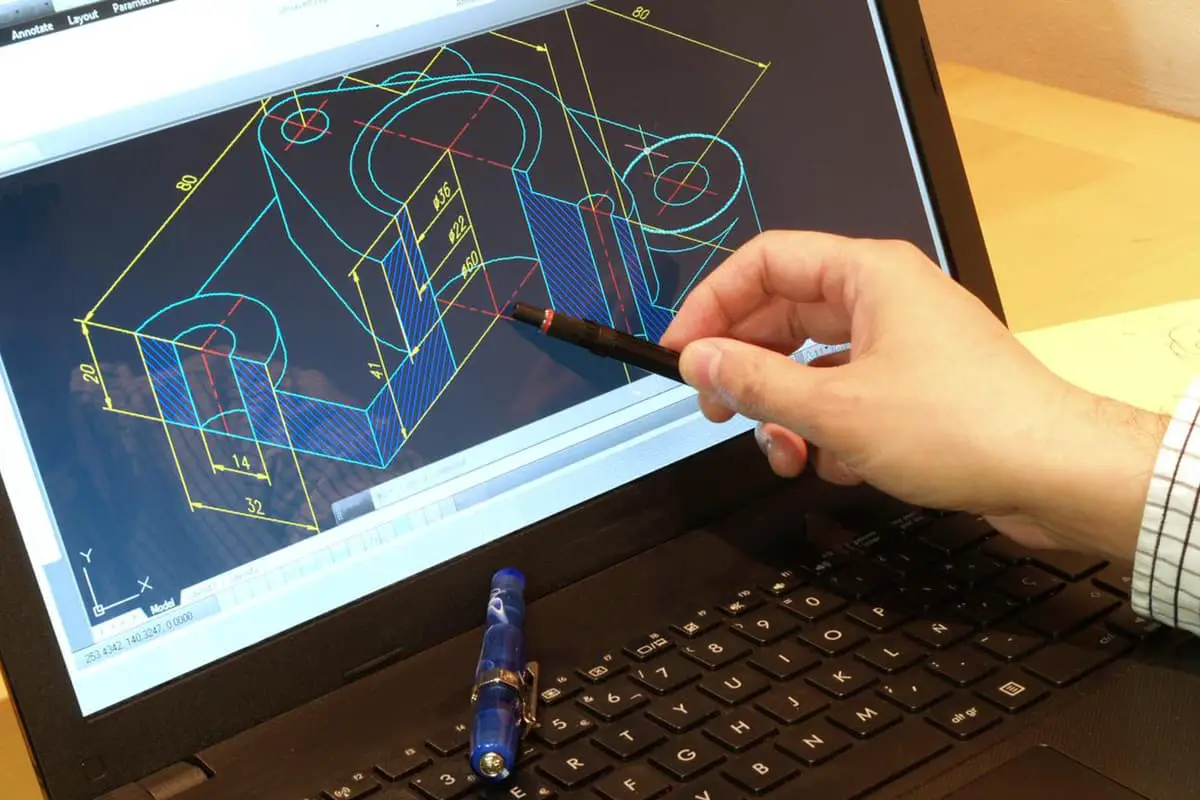
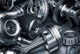
Have you ever wondered what makes mechanical design so crucial in engineering? This comprehensive guide on the basics of mechanical design explores essential concepts such as standardization, types of connections, bearing classifications, and gear mechanisms. Readers will gain a foundational understanding of key principles, aiding in efficient and innovative design processes. Dive into this article to enhance your knowledge and improve your mechanical design skills!

Table Of Contents

  1. The machine is composed of four parts: the prime mover, the transmission, the execution, and the control.
  2. The primary forms of failure in belt drives are fatigue damage and belt slippage.
  3. The importance of implementing standardization, serialization, and generalization in mechanical design:

① Reduces the design workload;

② Standard parts are produced in large quantities by professional factories with high efficiency, low cost, and reliable quality;

③ Makes maintenance and repair more convenient;

④ The principle of “Three Modernizations” should be followed in design and is also a national technical policy.

  1. Connections can be classified into two types: detachable and non-detachable.
  2. Screw connections can be divided into bolt connections, double-headed stud connections, and screw connections.
  3. Anti-loosening measures for threaded connections include friction anti-loosening, mechanical anti-loosening, and permanent anti-loosening.
  4. Pin connections are classified into locating pins, connecting pins, and safety pins.
  5. Key connections are divided into flat key connections, semicircular key connections, and spline connections.
  6. Shaft functions are classified into transmission shafts, spindles, and rotating shafts.
  7. Couplings are grouped into two categories: rigid and flexible couplings.
  1. Bearings can be classified into two types: sliding and rolling bearings.

Sliding bearings are further divided into radial and thrust bearings based on the load they carry.

  1. Definition of oil bearing: Oil bearings are made of powder metallurgy material, where metal powders such as bronze, iron, or aluminum are mixed with graphite to form bearing shells. These shells are sintered at high temperatures to produce non-compact and porous bearing shells with a ceramic structure. After being fully soaked in lubricating oil, the pores are filled with oil, hence the name “oil bearing.

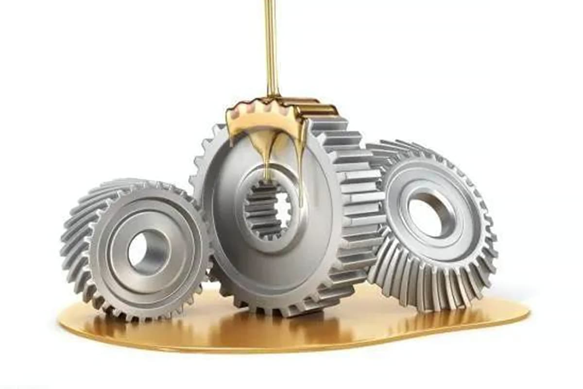
Features of oil bearing: low strength, no impact resistance, simple structure, and low cost.

  1. Rolling bearings:

Advantages:

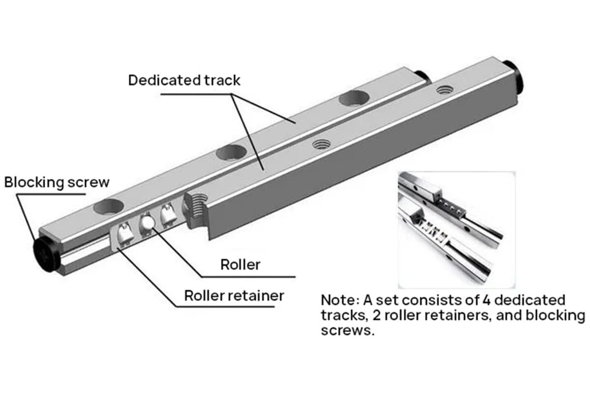
① Low friction resistance, sensitive starting, high efficiency, low heating, and low temperature rise;

② Small axial dimension contributes to the compactness and simplicity of the entire machine mechanism;

③ Small radial clearance, which can be adjusted by the pre-tightening method, leading to high rotation accuracy;

④ Simple lubrication, low oil consumption, and easy maintenance;

⑤ Standard parts, mass production, cost-effective, and easy to use and replace.

Disadvantages: large radial size, limited ability to bear impact loads, high noise when running at high speeds, and short working life.

  1. The components of a rolling bearing: outer ring, inner ring, rolling elements, and cage.
  2. Rolling bearing code: it consists of a pre-code, basic code, and post-code. The basic code includes the bearing type code, size series code, and inner diameter code.
  3. Structural forms of rolling bearings: double pivot one-way fixed support, single pivot two-way fixed support, double pivot floating support.
  4. Lubricants can be divided into lubricating oil and grease.
  5. The sealing of rolling bearings can be either contact or non-contact.
  6. Functions of springs:

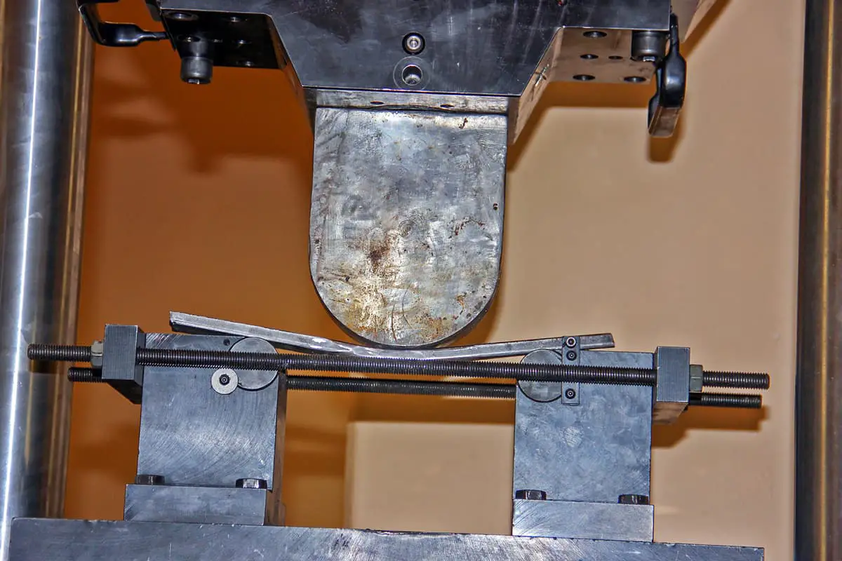
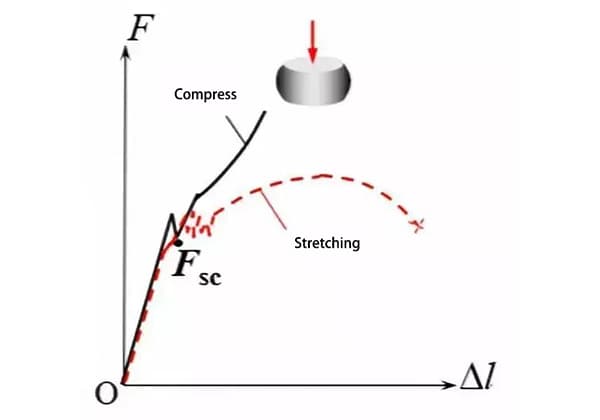
a. Reduce impact and absorb vibrations;

b. Control movement;

c. Store and release energy;

d. Provide measurement indication;

e. Maintain elastic contact.

  1. Springs are classified into different shapes, such as spiral springs, plate springs, disc springs, and ring springs.
  1. a. Methods of coiling springs: cold coiling and hot coiling.

b. Manufacturing process of cylindrical spiral springs: winding formation, end processing or hook production, and heat treatment.

  1. A moving pair is a movable connection between components in a machine that allows for both contact and relative motion.
  2. If the relative motion between the components of a kinematic pair occurs in the same plane or in parallel planes, it is known as a planar kinematic pair. If not, it is considered a spatial kinematic pair.
  3. Planar motion pairs are divided into planar low pairs and planar high pairs based on their different forms of contact.
  4. Common spatial motion pairs include spiral pairs and spherical pairs.
  5. Low pairs can be divided into rotating pairs and moving pairs based on the form of relative motion between the two components.
  6. Low and high pairs in everyday life:

① Low pairs: door and window hinges, ceiling fans, which have surface contact, can bear large loads, wear slowly, have long service lives, and low pressure, making them low pairs.

② High pairs: the meshing of gears, the ball heel ring of rolling bearings, the contact between train wheels and rails, and the contact between cams and push rods are all line or point contacts with high pressure. They allow for more accurate movement and high manufacturing requirements, making them high pairs.

  1. Three basic forms of a hinged four-bar mechanism:

① Crank-rocker mechanism (e.g. agricultural manual thresher, liquid mixer, rocking horse, sewing machine);

② Double crank mechanism (e.g. linkage mechanism of train wheels, umbrella);

③ Double rocker mechanism (e.g. electric fan oscillating mechanism, automobile wiper).

  1. a. Classification of cam mechanisms based on shape: moving cams, disc cams, and cylindrical cams.

b. Classification based on the shape of the follower: pointed followers, roller followers, and flat bottom followers.

c. Classification based on the movement form of the follower: direct moving followers and oscillating followers.

  1. Common mechanisms for intermittent motion: ratchet mechanism, Geneva mechanism, and incomplete gear mechanism.
  2. Features of belt drives:

Advantages:

① They can reduce impact, absorb vibrations, provide smooth operation, and have low noise;

② Simple structure, easy maintenance and replacement, and low cost;

③ Can easily achieve transmission between large center distances;

④ When overloaded, the conveyor belt will slip on the wheel to avoid damaging the machine.

Disadvantages:

① Cannot guarantee accurate and constant transmission ratio in belt transmission;

② Low mechanical transmission efficiency;

③ The shaft and shaft are subjected to large radial forces, which are unfavorable for machine operation.

  1. ① V-belt structure: divided into cord core structure and cord core structure, with top rubber layer (1), tensile layer (2), bottom rubber layer (3), and cladding layer (4);

② Neutral layer: located between the top and bottom rubber layers, its length and width do not change due to the tension of the V-belt on the pulley;

③ Pitch width: the width of the neutral layer of the V-belt;

④ There are three types of V-belt pulleys based on the size of their benchmark diameter: solid type, spoke plate type, and spoke type.

  1. Main types of belt transmissions: flat belt transmission, V-belt transmission, round belt transmission, and synchronous belt transmission.
  2. Characteristics of chain drives:

Advantages:

① Meshing transmission can ensure a constant average transmission ratio;

② No initial tension is required and there is minimal shaft bending force;

③ Greater strength compared to belt drives, allowing for the transmission of larger loads;

④ Strong adaptability, can be used in challenging work conditions.

Disadvantages:

① Cannot guarantee constant instantaneous transmission ratios like gears;

② High noise and vibration;

③ Higher manufacturing and installation requirements compared to belt drives;

④ The direction of the sprocket shaft is restricted.

  1. Characteristics of gear transmissions:

Advantages:

① High transmission accuracy;

② Wide range of applications;

③ Can achieve transmission between any two shafts in space;

④ Reliable operation and long service life;

⑤ High transmission efficiency.

Disadvantages:

① High manufacturing and installation requirements, and high cost;

② Strict requirements for ring mirror conditions, generally need to be placed in a cover to prevent dust and scale, and attention must be given to lubrication;

③ Not suitable for long-distance transmissions;

④ Vibration damping and impact resistance are not as good as belt transmissions.

  1. In mechanical transmission, the involute profile is usually adopted for gears to ensure smooth transmission, and involute gear transmission has a constant transmission ratio.
  2. The angle between the direction of force and the direction of movement of the point of force action on an object is called the pressure angle.
  3. A pair of involute gears must have equal modulus and pressure angle before meshing and transmission can occur.
  4. Main forms of gear damage: fracture from the tooth root, fatigue pitting on the tooth surface, tooth surface wear, and tooth surface bonding.
  5. Types of gear trains: fixed axle gear train and epicyclic gear train.
  6. Functions of gear trains:

① Obtain large transmission ratios;

② Achieve variable speed and reverse transmission;

③ Achieve multi-channel transmission;

④ Achieve gear transmission over large distances;

⑤ Synthesize and decompose motion.

  1. A transmission system composed of a series of meshing gear mechanisms is called a gear train.
  2. Screw transmission consists of a screw, nut, and machine rod.
  3. Chain drives consist mainly of a driving sprocket, chain, driven sprocket, frame, and other parts.
  4. Common forms of lubrication for closed gear transmissions: oil immersion lubrication and oil injection lubrication.
  5. Common types of gear structures: gear shaft, solid gear, spoke plate, and spoke gear.
  6. Components in a mechanism are divided into three types: frame, prime mover, and follower.
  7. Clutches are divided into jaw clutches, friction clutches, and overrunning clutches.
  8. Advantages of cam mechanisms: they can accurately realize any motion law and have a simple and compact structure.
  9. Basic forms of sliding bearings:

① Integral sliding bearings;

② Partial sliding bearings;

③ Self-aligning sliding bearings;

④ Thrust sliding bearings.

  1. Reducers consist of a box, bearing, shaft, shaft parts, and accessories.
Don't forget, sharing is caring! : )
Shane
Author

Shane

Founder of MachineMFG

As the founder of MachineMFG, I have dedicated over a decade of my career to the metalworking industry. My extensive experience has allowed me to become an expert in the fields of sheet metal fabrication, machining, mechanical engineering, and machine tools for metals. I am constantly thinking, reading, and writing about these subjects, constantly striving to stay at the forefront of my field. Let my knowledge and expertise be an asset to your business.

You May Also Like
We picked them just for you. Keep reading and learn more!
The Ultimate Guide to Mechanical Structure Design

The Ultimate Guide to Mechanical Structure Design

Have you ever wondered how mechanical structures transform ideas into tangible designs? Mechanical structure design turns abstract principles into detailed schematics, ensuring every part is optimized for functionality, strength, and…
Mechanical Equipment Lubrication

Mechanical Equipment Lubrication: The Ultimate Guide

Ever wondered how proper lubrication can make or break industrial equipment? This article delves into the critical role of mechanical equipment lubrication, detailing its significance in preventing wear, reducing maintenance…
MachineMFG
Take your business to the next level
Subscribe to our newsletter
The latest news, articles, and resources, sent to your inbox weekly.
© 2024. All rights reserved.

Contact Us

You will get our reply within 24 hours.