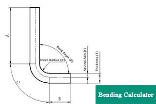
0° – 180° Bend Allowance Chart for Sheet Metal Bending
Have you ever wondered how sheet metal parts are designed and manufactured with precision? In this blog post, we'll dive into the fascinating world of bend allowance - a crucial…
Have you ever struggled with accurately unfolding sheet metal parts? This article explores the art and science behind sheet metal unfolding calculations. Discover the key concepts, formulas, and techniques used by experienced engineers to precisely unfold complex geometries. Learn how to apply these principles to your own designs and streamline your manufacturing process.

The first step in the sheet metal fabrication process is the unfoldment of the geometries and the coherent body. The accuracy and correctness of the sample unfoldment directly impacts the quality of the final part.
In the past, due to the limitations of calculation tools, people would use the projection method to enlarge the sample on a plane with a 1:1 ratio and measure the real length of the required plan line.
However, this method is complicated and inefficient, and cannot meet the current demands of production.
With the advancements in calculation tools, such as electronic calculators and widespread use of computers, sheet metal unfolding can now be performed using calculation methods.
To standardize the calculation method of sheet metal unfolding coefficient by technicians, minimize dimensional deviations of products after bending, and facilitate self-inspection by workshop personnel and re-inspection by quality inspectors, there is a unified standard and basis for the unfolding coefficient.
As a result, the calculation standard for the sheet metal unfolding coefficient has become increasingly standardized.
Neutral Layer Unfolding Method
In the bending process, the outer layer undergoes tensile stress, while the inner layer experiences compressive stress. The transition layer between tensile and compressive stress is referred to as the neutral layer. The length of the neutral layer during bending remains the same as before bending, making it the benchmark for determining the unfolded length of the bent part.
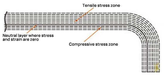
The location of the neutral layer is dependent on the degree of deformation.
The position of the neutral layer is not only related to the bending radius, plate thickness, inward shift coefficient, etc., but also to factors such as processing method, sheet metal shape, and size.
Therefore, the position of the neutral layer can only be approximately determined, and in practical applications, approximate values are generally used for calculation.
The calculation formula for the length dimension L of the neutral layer is:
Among them,
By using 3D software to perform simulations and calculations of various thicknesses, angles, and radii, along with on-site fabrication practices, we have compiled a set of K-factor values. Please refer to Table 1 for the specific values.
Table 1: Neutral Layer Coefficient K-Values
| r/t | ≤05 | 0.6 | 0.8 | 1 | 1.2 | 1.3 | 1.5 | 2 | 2.5 | 3.0 | 4.0 | 5.0 | 6.0 | ≥8 |
| k | 026 | 0.28 | 0.30 | 0.32 | 0.33 | 0.34 | 0.36 | 0.38 | 0.39 | 0.4 | 0.42 | 0.44 | 0.46 | 0.5 |
Rapid Unfolding Calculation for 90° Bends
The unfolding diagram for a 90° bend is shown in Figure 9. In recent years, we have used 3D software like CATIA and SOLIDWORKS for sheet metal modeling to calculate unfolding dimensions.
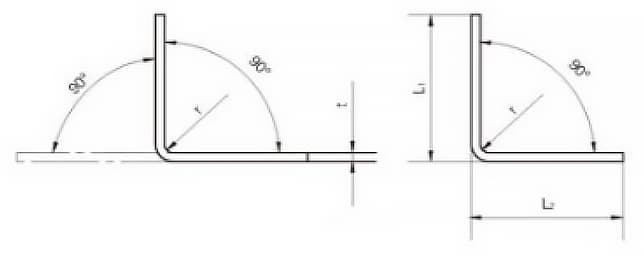
Through repeated verification, it has been observed that when the cold bending angle of flat steel products is 90°, the formula for calculating the unfolded length L is:
L = L1 + L2 – A
Where,
Table 2 90 ° Bending Parameters Table
| Thickness t/mm | Beding radius r/mm | |||||||||||
| 1 | 1.2 | 16 | 2 | 25 | 3 | 4 | 5 | 6 | 8 | 10 | 12 | |
| Compensation value A mm | ||||||||||||
| 1 | -1.92 | -1.97 | -2.10 | -2.23 | -2.41 | -2.59 | -2.97 | -3.36 | -3.79 | -4.65 | -5.51 | -6.37 |
| 1.5 | -2.90 | -3.02 | -3.18 | -3.34 | -3.70 | -4.07 | -4.45 | -5.26 | -6.11 | -6.97 | ||
| 2 | -3.84 | -3.98 | -4.13 | -4.46 | -4.81 | -5.18 | -5.94 | -6.72 | -7.58 | |||
| 2.5 | -4.80 | -4.93 | -5.24 | -5.57 | -5.93 | -6.66 | -7.42 | -8.21 | ||||
| 3 | -5.76 | 6.04 | -6.35 | -6.69 | -7.40 | -8.14 | -8.91 | |||||
| 4 | -7.7 | -7.95 | -8.26 | -8.92 | -9.62 | -10.36 | ||||||
| 5 | -9.6 | -9.87 | -10.48 | -11.15 | -11.85 | |||||||
| 6 | -11.5 | -12.08 | -12.71 | -13.38 | ||||||||
| 8 | -15.4 | -15.9 | -16.51 | |||||||||
| 10 | -19.2 | -19.73 | ||||||||||
| 12 | 23.01 | |||||||||||
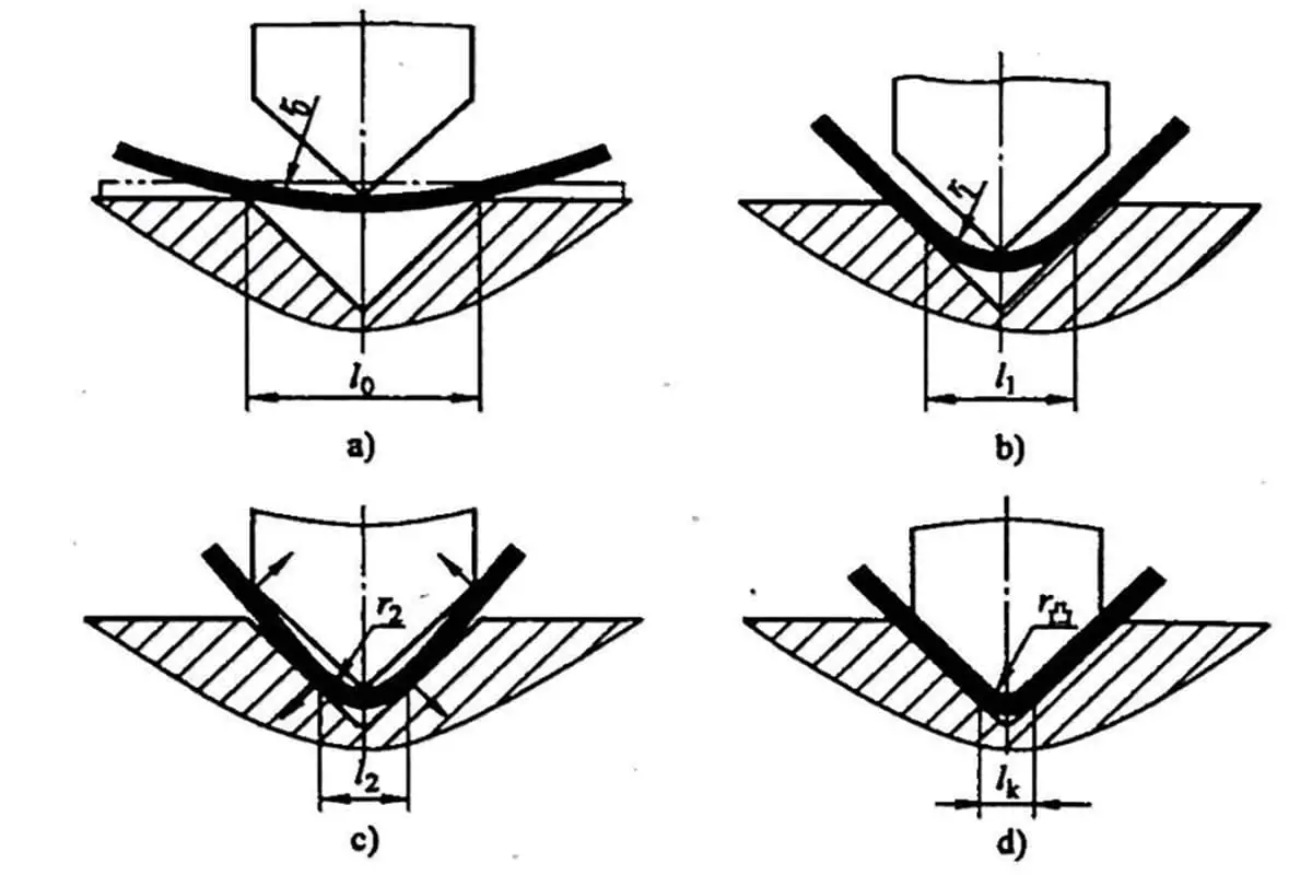
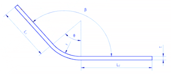
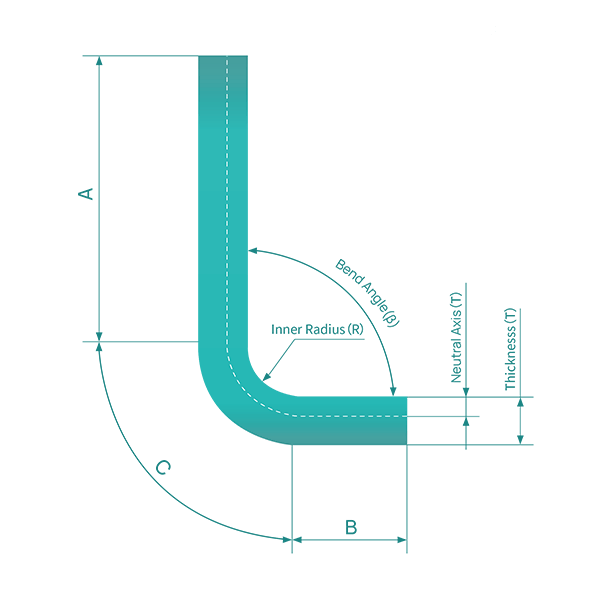
When the bending radius is large and the bending angle is small, the degree of deformation is low and the neutral layer is close to the center of the sheet thickness.
However, when the bending radius (R) becomes smaller and the bending angle (θ) increases, the degree of deformation also increases and the neutral layer moves towards the inner side of the bending center. The distance from the neutral layer to the inner side of the sheet is denoted by λ, and the material thickness is denoted by T.
The basic formula for calculating the unfold length:
Unfolding length = inner size of material + inner size of material + amount of compensation.
You can also use the following calculator to calculate sheet metal unfold length:
The following describes the unfolding algorithms of various bend features one by one.
R = 0mm, θ = 90° (Note: When R ≤ 1.0mm, it is treated as R = 0mm).
L = A + B + K
In actual production, the bending upper die may wear an R angle, or there may be an R angle less than 1mm, or the choice of the lower die‘s V slot may be large, among other reasons, resulting in a small bending coefficient. As a result, the bending coefficient of each material plate thickness is presented in Table 1 based on actual empirical values.
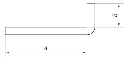
Fig. 1 Schematic diagram of general bending I
R ≠ 0mm and θ = 90°
L = A + B + K (K is the arc length of neutral layer )
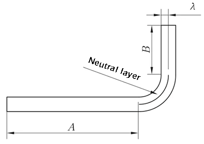
Fig. 2 Schematic diagram of general bending II
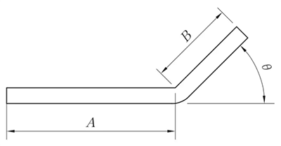
R = 0mm, θ ≠ 90°
L = A + B + K’
Note: K is the compensation amount at 90°.
R ≠ 0mm, θ ≠ 90°
L = A + B + K
(K takes the neutral layer arc length)
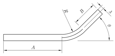
Fig. 4 General bending IV bending diagram
The Unfolding Method is equivalent to the Parallel Straight-Edge Z-Fold Method, and the measurement for height is demonstrated in Figure 6.
The angle θ is considered a 90° unfolding.
For 0 < T ≤ 1.6mm, λ equals 0.5T.
When T is greater than 1.6mm, λ equals 0.4T.
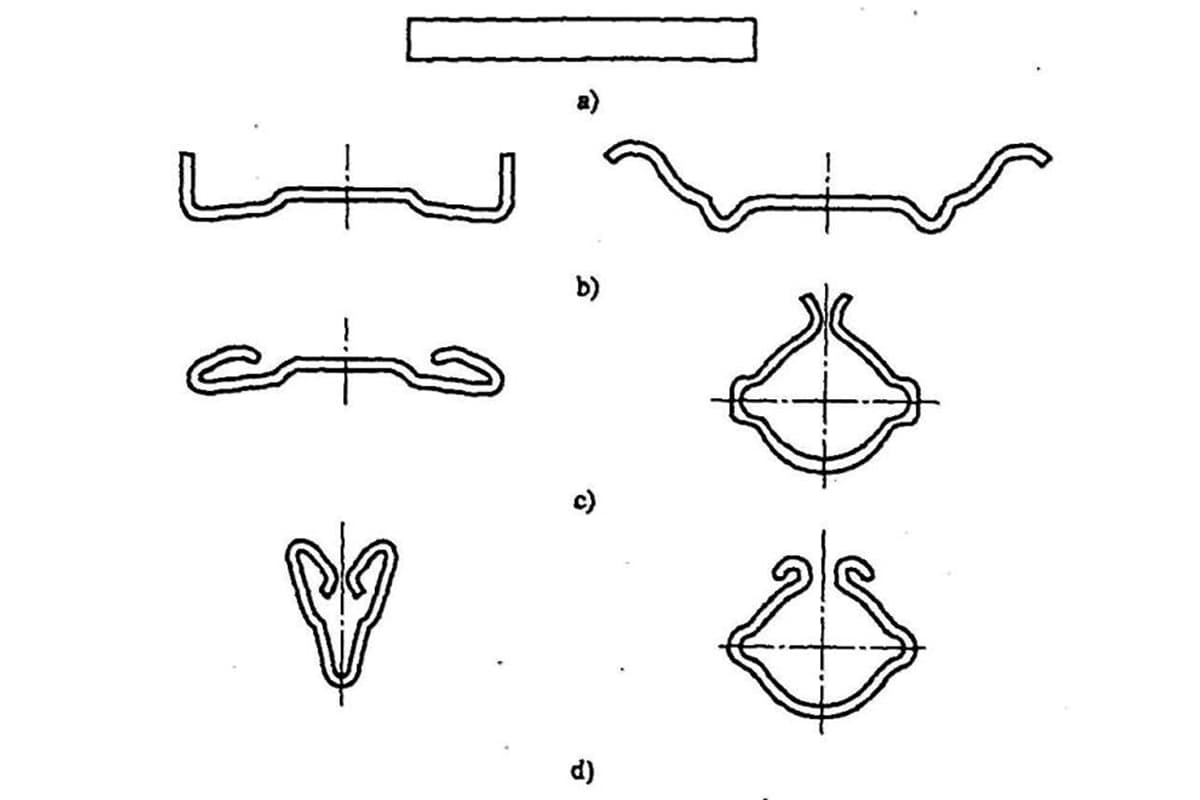
Z-Fold, also referred to as Offset Bending, is differentiated into Straight-Edge Offset Bending and Bevel-Edge Offset Bending based on the forming angle, and the method of processing is determined by the offset height.
When the offset height, h, is less than 3.5 times the thickness of the material, offset dies or changeable dies are used for forming.
If the offset height exceeds 3.5 times the material thickness, normal positive and negative forming is employed.
When the length of the beveled edge is less than 3.5 times the material thickness, offset dies or changeable dies are used for forming.
If the length of the beveled edge exceeds 3.5 times the material thickness, normal one-positive and one-negative folding is applied.
(1) When H < 3.5T, only then can be processed by offset bending.
L = A + B + H
(if H ≤ T, then compensate 0.2mm)
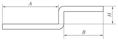
Fig. 5 Schematic diagram of straight edge offset
(2) Non-parallel straight-edge offset
The expansion method is the same as the parallel straight-edge Z-fold method, and the height value is shown in Figure 6.
Angle θ can be considered as 90 ° unfold.
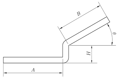
Fig. 6 Schematic diagram of non-parallel straight edge offset
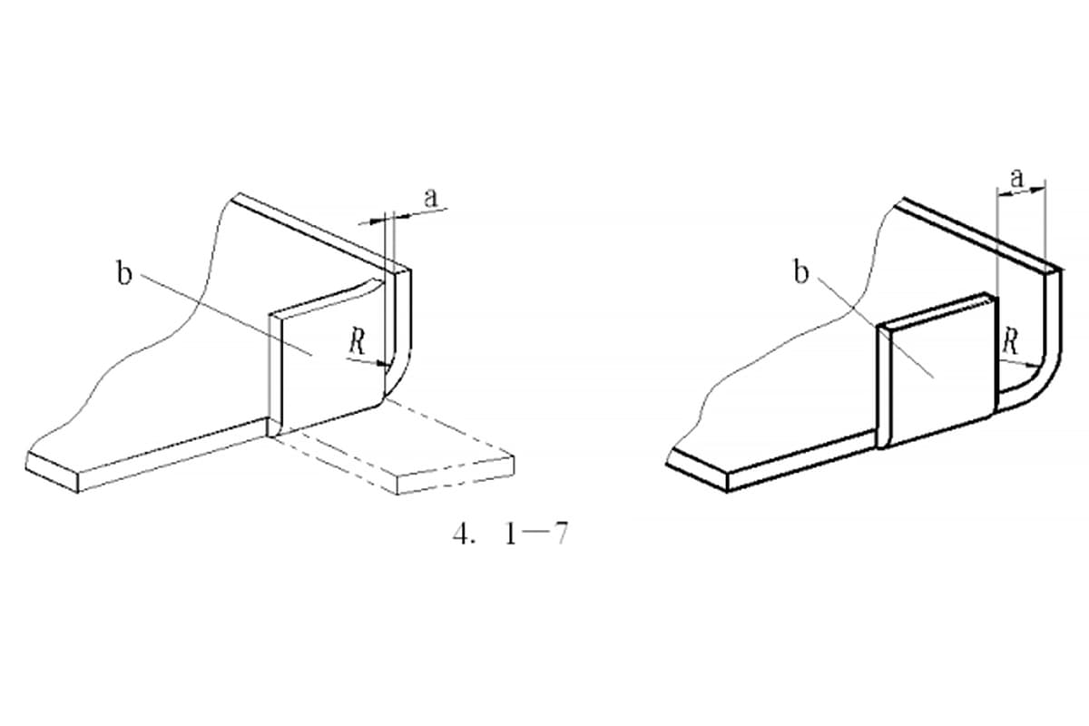
(3) Straight edge offset – the transition segment is tangent to two arcs
When the Straight-Edge Offset is unfolded at the tangent point of two circular arcs, a vertical line is created at the tangent point of the two circular arcs on the outer surface of the substrate. The material is then offset by one material thickness inward, as depicted in Figure 7, for processing and unfolded using the Z-Fold 1 (Straight-Edge Offset) method.
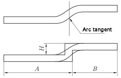
Fig. 7 Straight edge offset diagram – transition segment is tangent to two circular arcs
When H < 2T, the unfolding algorithm is as follows according to the offset processing.
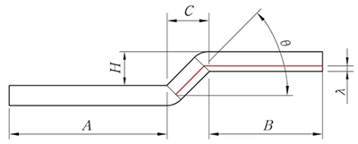
Fig. 8 Diagram of beveled edge offset
L = A + B – K
(1) When flattening, consider pressing the line prior to bending based on the actual conditions.
The line pressing location is in the center of the bending deformation area.
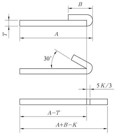
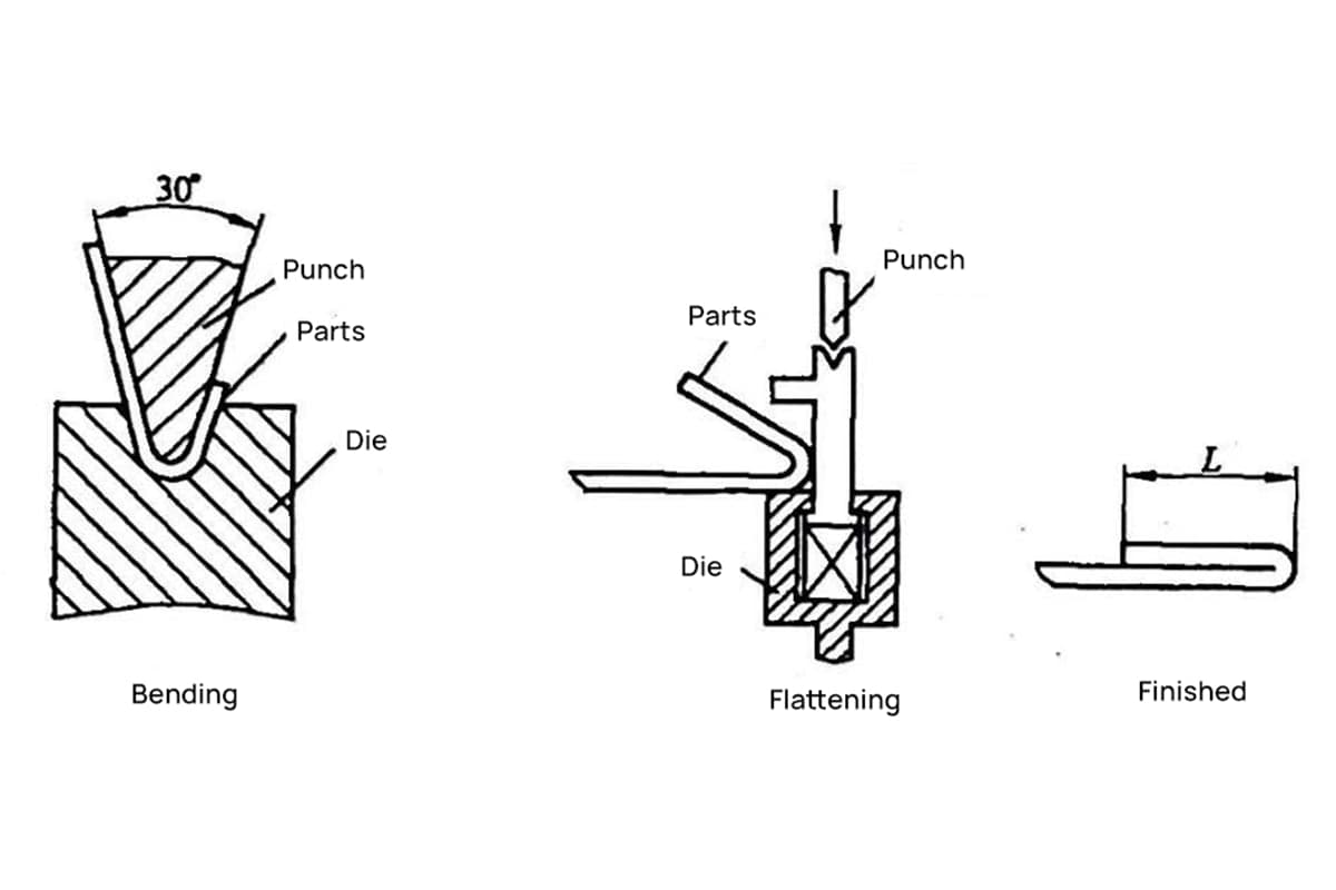
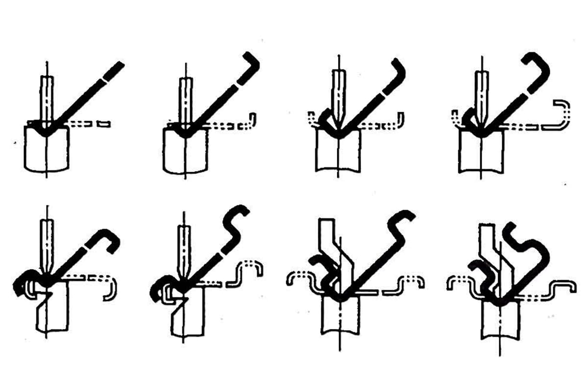
Fig. 9 Schematic diagram of reverse folding and flattening
The Reverse Folding and Flattening processes are usually performed in two steps: first, the material is bent to 30° using the insertion die, followed by flattening.
Therefore, when creating the bending line on the expanded drawing, it is essential to illustrate the bending line based on the 150° bending, as demonstrated in Figure 9.
Table 1 bending coefficient of plates with different thicknesses under different bending angles
| Angle | Thickness/mm | ||||
|---|---|---|---|---|---|
| 1 | 1.2 | 1.5 | 1.8 | 2.5 | |
| 45° | 5.3 | 6.3 | 7.8 | 9.5 | 13 |
| 50° | 4.5 | 5.4 | 6.8 | 8.1 | 11.25 |
| 55° | 4 | 4.7 | 5.8 | 7.05 | 9.75 |
| 60° | 3.4 | 4.1 | 5.1 | 6.15 | 8.5 |
| 65° | 3 | 3.6 | 4.5 | 5.4 | 7.5 |
| 70° | 2.65 | 3.2 | 4 | 4.75 | 6.6 |
| 75° | 2.35 | 2.8 | 3.5 | 4.25 | 5.9 |
| 80° | 2.1 | 2.5 | 3.1 | 3.75 | 5.25 |
| 85° | 1.9 | 2.25 | 2.8 | 3.35 | 4.65 |
| 90° | 1.7 | 2 | 2.5 | 3 | 4.15 |
| 95° | 1.5 | 1.8 | 2.2 | 2.7 | 3.75 |
| 100° | 1.35 | 1.6 | 2 | 2.4 | 3.35 |
| 105° | 1.2 | 1.4 | 1.75 | 2.15 | 3 |
| 110° | 1.1 | 1.3 | 1.6 | 2 | 2.65 |
| 115° | 1 | 1.25 | 1.4 | 1.7 | 2.35 |
| 120° | 0.85 | 1 | 1.25 | 1.5 | 2.1 |
| 125° | 0.75 | 0.9 | 1.1 | 1.35 | 1.85 |
| 130° | 0.65 | 0.8 | 1 | 1.18 | 1.65 |
| 135° | 0.55 | 0.7 | 0.85 | 1.05 | 1.45 |
| 140° | 0.5 | 0.6 | 0.75 | 0.9 | 1.25 |
| 145° | 0.43 | 0.5 | 0.65 | 0.77 | 1.05 |
| 150° | 0.35 | 0.43 | 0.55 | 0.65 | 0.9 |
| 155° | 0.3 | 0.35 | 0.45 | 0.53 | 0.75 |
| 160° | 0.23 | 0.27 | 0.35 | 0.4 | 0.6 |
| 165° | 0.17 | 0.2 | 0.25 | 0.3 | 0.45 |
The N-fold processing method involves both reshaping and flattening, and the algorithm for unfolding is:
L = A + B + K
(K takes the neutral layer arc length).
λ = 0.5T
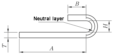
Fig.10 N-fold diagram
(1) The arc expansion is directly K, and the arc length of the neutral layer is taken. λ= 0.5T
(2) Expansion with the straight edge on one side.
L = A + K
(k is the arc length of the neutral layer)
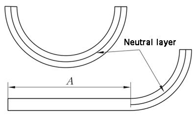
Fig. 11 Schematic diagram of arc bending
In actual production, the precise control of the unfolded length of sheet metal through 3D software can mainly be achieved through the following steps and methods:
Choose the right 3D design software: First, you need to choose a 3D CAD software suitable for sheet metal design. SolidEdge, Creo, FreeCAD, UG, etc. are all software that can be used for sheet metal design. These software provide sheet metal modules or related functions that can help designers with the design and unfolding calculations of sheet metal parts.
Use the sheet metal module or tools in the software: Most 3D CAD software provides related tools and functions for sheet metal design. For example, Creo offers a variety of methods for controlling the unfolded dimensions of sheet metal, including the modeling and unfolding methods of large arc sheet metal parts, bend deduction method, etc. FreeCAD, as an open-source 3D modeling software, also provides a sheet metal module.
Apply unfolding calculation methods: To ensure the accuracy of the length after the sheet metal is unfolded, different unfolding calculation methods can be used. Common methods include the bend compensation method, bend deduction method, and K-factor calculation method. These methods can help designers calculate the actual length of the material in the unfolded state, thereby ensuring the expected size of the parts after the final bending and forming.
Pay attention to edge and corner handling and detail adjustment: In the process of sheet metal design, the details of edge and corner handling are very important. Some software, such as SW, provides a variety of edge and corner handling solutions and bending methods, which helps to improve unfolding accuracy.
For non-90-degree bends, common bend angles include but are not limited to 45 degrees and 135 degrees. The calculation method for the K factor is based on the ratio between material thickness and bend radius.
Specifically, the K factor = δ / T, where δ represents the material thickness and T represents the bend radius. This method is applicable for calculating the bend coefficient of any non-90-degree angle.
In practical applications, due to the possible differences and large errors in the deduction values of bends at different angles, the K factor is generally used as the bend coefficient.
Moreover, to accurately guide the K factor value of different plate thicknesses, adjustments are necessary. Some references suggest that the K factor value for any bend radius can be calculated through specific interpolation techniques, which have been proven effective for industrial sheet metal applications.
The calculation formula for the expanded length of beveled press-brake sheet metal is: [L = A + B + C + 0.2], where (A), (B), and (C) represent the internal dimensions, and 0.2 serves as a compensation value.
Based on the general principles and practices of sheet metal expansion calculations, this compensation value accounts for discrepancies between the actual and theoretically calculated lengths due to factors such as material bending and mold precision errors during real-world operations.
In sheet metal processing, this compensation value aids in ensuring the dimensional accuracy and quality of the final product.
Sheet metal parts are utilized extensively in the electromechanical, light industry, and automotive industries.
The unfolded form of sheet metal parts is the primary determining factor for blank size, which in turn affects the size and shape of the blank.
However, traditional methods of unfolding sheet metal parts have become increasingly inadequate in meeting modern design needs due to their long cycles, low efficiency, and poor quality.
To address these shortcomings, the use of advanced CAD systems has become increasingly prevalent in recent years.
These specialized sheet metal part design systems boast robust functionality and can greatly reduce the amount of time and effort required for the preliminary design and deployment of sheet metal parts.

As the founder of MachineMFG, I have dedicated over a decade of my career to the metalworking industry. My extensive experience has allowed me to become an expert in the fields of sheet metal fabrication, machining, mechanical engineering, and machine tools for metals. I am constantly thinking, reading, and writing about these subjects, constantly striving to stay at the forefront of my field. Let my knowledge and expertise be an asset to your business.