Achieving Optimal Cam Drive Mechanism Design: Key Points to Consider
How can a simple cam and follower system lead to efficient, precise motion in complex machinery? This article explores the intricacies of cam drive mechanism design, explaining the different types of cams and followers, their motion paths, and how to achieve optimal performance. From the basic components to advanced design methods, readers will gain valuable insights into creating highly efficient cam systems. Expect to learn practical tips and detailed analysis that will enhance your understanding and application of cam mechanisms in engineering projects.
The Composition and Classification of Cam Mechanisms
The cam mechanism usually consists of two moving parts, namely the cam and the follower, both of which are fixed to the frame. The cam device is highly versatile, and can generate almost any arbitrary motion.
A cam can be defined as a component with a curved surface or groove. By swinging or rotating it, another component, the follower, can provide pre-set motion. The path of the follower is mostly limited to a slot in order to obtain reciprocating motion.
While sometimes relying on its own weight during the return stroke, some mechanisms use springs as a returning force to achieve precise movements. Others use guide rails to move along specific paths.
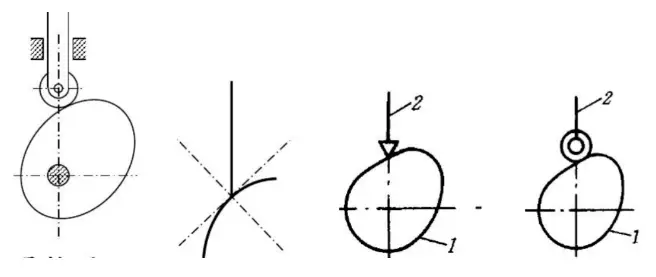
According to the shape of the cam, it can be divided into three types: disc cam, moving cam, and cylindrical cam.
Followers can be divided according to their ends into three types: pointed followers, roller followers, and flat-bottomed followers.
Due to the point contact between the sharp-nose follower and the cam, which leads to high stress and rapid wear, it is not suitable for low-speed cam mechanisms with large impact. The roller follower can overcome these shortcomings.
In order to improve transmission efficiency, we can also introduce a flat-bottomed follower that is perpendicular to the direction of force on the bottom surface.
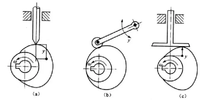
The transmission components we considered earlier are in the form of straight-line motion, but they can also be in the form of oscillating motion. The former is called a direct-acting follower, and the latter is called a swinging follower.
We can also make the cam rotation center not on the linear path of the follower’s motion. At this time, we call it offset. Correspondingly, if the rotation center is on the linear path of the follower’s motion, we can call it concentric.
In addition, we can also consider methods to maintain high-stress locking relationships and divide the mechanism into geometric locking and force locking.
By combining the cam shape, the end of the follower, and the follower’s movement patterns, we can determine the name of the designed mechanism, such as: the disc cam with a sharp-nose direct-acting follower (follower-cam relative position + follower end + follower movement pattern + cam shape).
The Movement Process of Cam Mechanisms
Cam mechanism
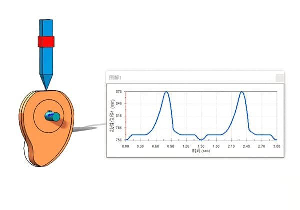
First, we have a cam with a follower placed on it. When the cam rotates at an angular velocity ω by φs degrees, the follower does not move. At this time, we call φs the dwell angle, and the circle corresponding to it is called the base circle. Similarly, the radius of this circle is called the base circle radius r0.
Then, as we continue to rotate the cam at an angular velocity ω by φ degrees, the follower rises by h. At this time, we call φ the stroke angle, and h is called the stroke.
Later, when the follower reaches point h, we let it stay for a period of time. Meanwhile, the cam rotates by φs’, which corresponds to the lift angle.
Finally, we need to bring the follower back to its original position, so we rotate the cam by φ’. At this time, the follower returns to the starting point. We call φ’ the return angle.
How to Design a Cam Mechanism?
There are two main methods for designing cam mechanisms, one is the graphical method and the other is the analytical method.
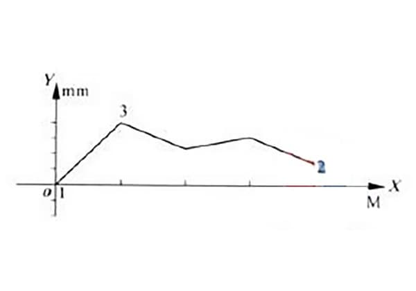
The former is relatively simple, only requiring the desired push motion diagram to be provided, and then obtaining the corresponding contour curve based on the angle-process relationship provided by the diagram.
The accuracy is not very high. The latter is calculated, and its calculation is relatively complex, which is suitable for designing cam mechanisms with high precision requirements.
As the founder of MachineMFG, I have dedicated over a decade of my career to the metalworking industry. My extensive experience has allowed me to become an expert in the fields of sheet metal fabrication, machining, mechanical engineering, and machine tools for metals. I am constantly thinking, reading, and writing about these subjects, constantly striving to stay at the forefront of my field. Let my knowledge and expertise be an asset to your business.
How can you prevent your molds from cracking during heat treatment? This article dives into the intricate process of mold heat treatment, outlining common defects like quenching cracks and insufficient…
Have you ever thought about the precision required in tightening flange bolts? Proper technique can prevent leaks and ensure safety in high-pressure systems. This article delves into essential methods for…
How do you measure the straightness of a guide rail to ensure precise machine operations? This article explores two common methods: the two-end point connection method and the minimum condition…
How do polishing machines achieve that perfect finish on metal surfaces? In this article, we explore the intricate mechanics behind these essential tools. From the components involved to the dual-stage…
Imagine producing thousands of intricate plastic parts every day with pinpoint accuracy and speed. Injection molding, a transformative manufacturing technique, makes this possible by injecting molten material into molds to…
In today's fast-paced manufacturing world, efficient deburring is crucial. With numerous methods available, choosing the right one can be daunting. In this blog post, we'll explore various deburring techniques, from…
Have you ever wondered what keeps our gas systems running smoothly and safely? In this article, we explore top gas regulator manufacturers, uncovering their innovations and contributions to the industry.…
Have you ever wondered what powers the machines that drive our world? Gearboxes are the unsung heroes behind many industries, from automotive to wind energy. In this article, you'll explore…
Are you aware of the pivotal players in the centrifugal pump industry? This article dives into the leading manufacturers revolutionizing the market with innovative and reliable pumping solutions. From Bosch…