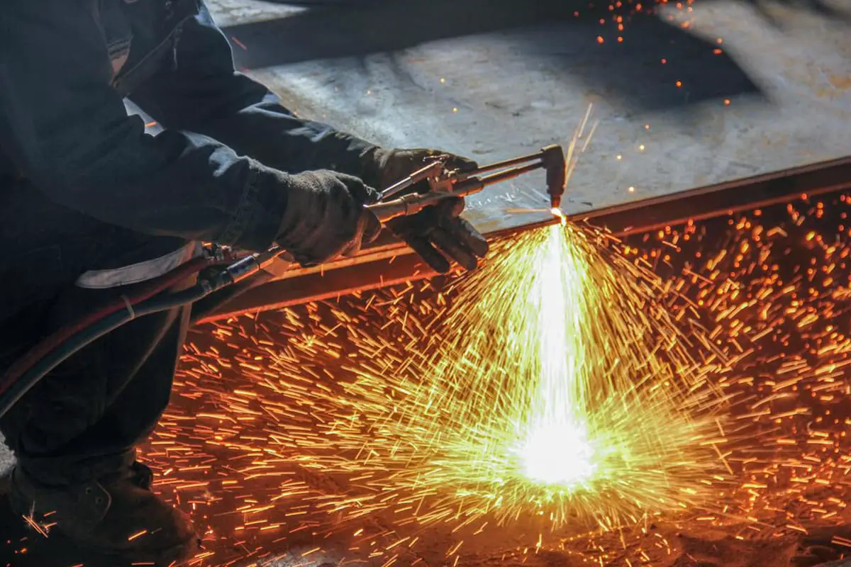
Gas Welding and Cutting: Choosing the Right Flame and Parameters
What’s the secret behind flawless welds and precise cuts in gas welding and cutting? It all comes down to the flame. This article explores the different types of flames used…
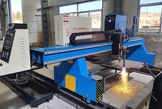
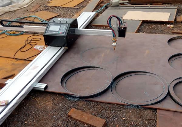
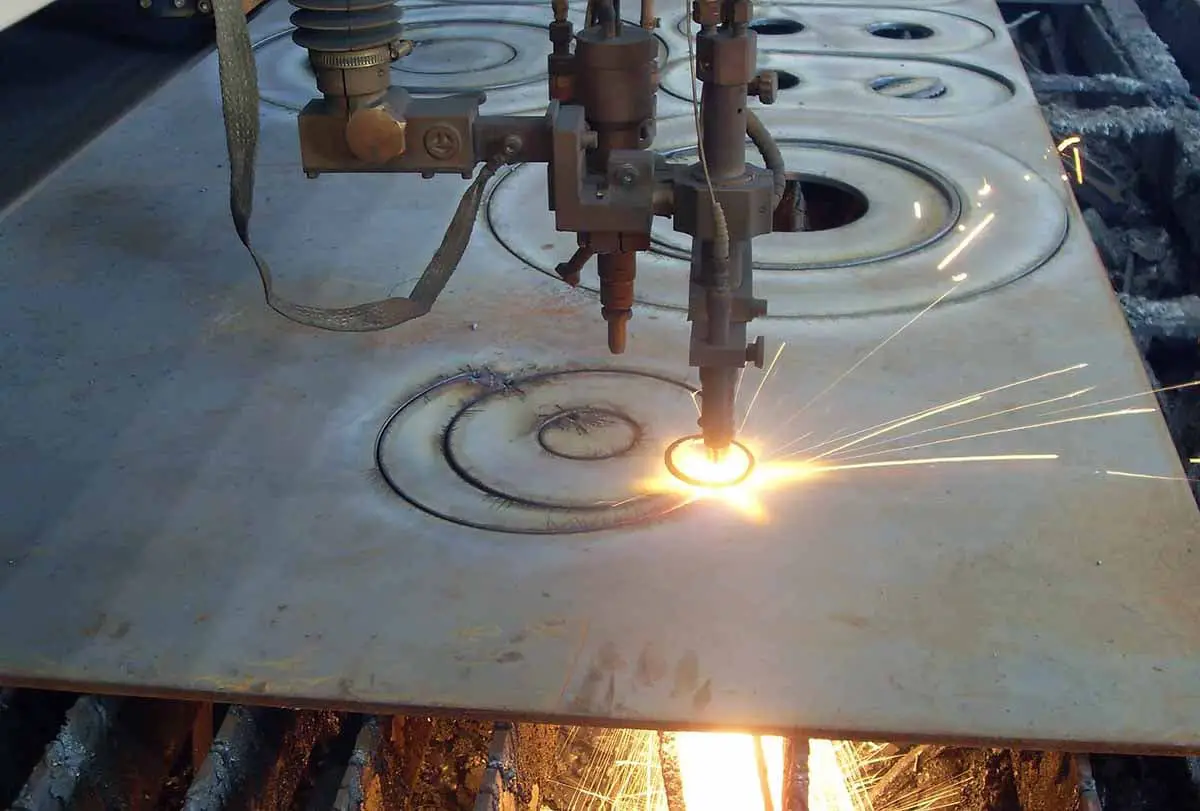
Have you ever wondered how to achieve flawless cuts with CNC plasma machines? Mastering cutting parameters is the key. This article dives into the essential aspects like cutting current, speed, and gas flow, offering you the know-how to enhance your cutting precision and efficiency. By understanding these parameters, you’ll be equipped to optimize your CNC plasma cutting process, ensuring high-quality results every time. Ready to transform your cutting skills? Read on to unlock the secrets.
The selection of cutting process parameters for CNC plasma cutting machines is crucial to the quality, speed and efficiency of the cutting results.
To use a CNC plasma machine correctly for high-quality and fast cutting, it is essential to have a profound understanding and mastery of the cutting process parameters.
The cutting current is the most critical parameter in the plasma cutting process, as it directly influences the thickness and speed of the cut, thereby determining the cutting ability. The effects of cutting current are as follows:
The optimal cutting speed range can be determined according to the equipment instructions or through experimentation. Various factors such as material thickness, material type, melting point, thermal conductivity, and surface tension after melting influence the cutting speed. The main effects of cutting speed are as follows:
The arc voltage, typically considered the cutting voltage, is another crucial parameter in plasma cutting. Plasma arc cutting machines usually operate with high no-load voltage and working voltage. The effects of arc voltage are as follows:
In plasma arc cutting, the selection and management of working gases are crucial for achieving optimal cutting performance. The working gases typically include cutting gas, auxiliary gas, and, in some cases, starting gas. The appropriate working gas should be selected based on the type, thickness, and cutting method of the material being processed.
The cutting gas serves several essential functions:
The gas flow rate is a critical parameter that must be carefully controlled:
Therefore, the gas flow rate must be well-coordinated with the cutting current and speed to maintain cutting efficiency and quality.
Most modern plasma arc cutting machines control the gas flow rate by adjusting the gas pressure. When the nozzle aperture is fixed, controlling the gas pressure effectively controls the flow rate. The gas pressure required for cutting a specific material thickness is usually provided by the equipment manufacturer. For special applications, the gas pressure may need to be determined through actual cutting trials.
The most commonly used working gases in plasma arc cutting include:
Each gas or gas mixture has specific properties that make it suitable for different materials and cutting conditions. For instance:
Argon gas exhibits minimal reactivity with metals at high temperatures, contributing to a highly stable plasma arc. The longevity of the nozzle and electrode is also enhanced when using argon. However, the argon plasma arc operates at a lower voltage and has a relatively low enthalpy value, which limits its cutting capability. Compared to air cutting, the cutting thickness achievable with argon decreases by approximately 25%. Additionally, in an argon-protected environment, the surface tension of the molten metal is about 30% higher than in a nitrogen environment, potentially leading to more slag formation. Even when mixed with other gases, argon tends to produce sticky slag, making pure argon gas less favorable for plasma cutting.
Hydrogen gas is typically used as an auxiliary gas in combination with others. A notable example is H35 gas, which consists of 35% hydrogen and 65% argon. This mixture is highly effective in plasma arc cutting due to the significant increase in arc voltage provided by hydrogen, resulting in a high enthalpy plasma jet. When combined with argon, the cutting efficiency is markedly improved. For cutting metal materials thicker than 70 mm, an argon-hydrogen mixture is commonly employed. The cutting efficiency can be further enhanced by using a water jet to compress the argon-hydrogen plasma arc.
Nitrogen is a widely used working gas in plasma cutting. Under high power supply voltages, nitrogen plasma arcs offer better stability and higher jet energy compared to argon. This makes nitrogen particularly effective for cutting high-viscosity materials such as stainless steel and nickel-based alloys, with minimal slag formation. Nitrogen can be used alone or mixed with other gases. In automated cutting processes, nitrogen or air is often used, making them standard gases for high-speed cutting of carbon steel. Nitrogen is also used as an arc-starting gas in oxygen plasma cutting.
Oxygen can significantly increase the cutting speed of low-carbon steel. The cutting mechanism with oxygen is similar to flame cutting, where the high-temperature, high-energy plasma arc accelerates the cutting process. However, oxygen must be used with electrodes that are resistant to high-temperature oxidation and protected against impact during arc initiation to prolong their lifespan.
Air, containing approximately 78% nitrogen and 21% oxygen, produces slag formation similar to nitrogen when used for cutting. The presence of oxygen in air enhances the cutting speed of low-carbon steel. Air is also the most economical working gas. However, using air alone for cutting can lead to issues such as slag formation, oxidation, and nitrogen increase at the cut edges. The reduced lifespan of electrodes and nozzles can also impact work efficiency and increase cutting costs.
Nozzle height refers to the distance between the nozzle end face and the cutting surface. This distance is a critical parameter in plasma arc cutting as it influences the overall arc length and, consequently, the cutting performance.
Plasma arc cutting typically employs power sources with constant current or steep drop characteristics. When the nozzle height increases, the current remains relatively stable. However, the arc length increases, leading to a rise in arc voltage and, thus, arc power. This increase in arc power is counterbalanced by the energy loss of the arc column exposed to the environment.
The interplay between increased arc power and energy loss can result in a reduction of effective cutting energy. This reduction manifests in several ways:
To improve cutting speed and quality, it is generally beneficial to maintain the smallest possible nozzle height. However, if the nozzle height is too low, it can lead to the formation of double arcs, which are detrimental to the cutting process.
Using ceramic outer nozzles can mitigate the issues associated with low nozzle heights. These nozzles allow the nozzle end face to directly contact the cut surface, effectively setting the nozzle height to zero. This configuration can achieve excellent cutting results by minimizing the arc length and maximizing the effective cutting energy.
To achieve a high-compression plasma arc for cutting, the cutting nozzle employs a small nozzle aperture, an extended bore length, and enhanced cooling mechanisms. These features collectively increase the current passing through the nozzle’s effective cross-sectional area, thereby boosting the arc power density. However, this compression also results in increased power loss of the arc. Consequently, the actual energy utilized for cutting is less than the power output from the power source, with a typical loss rate ranging between 25% and 50%.
Certain methods, such as water compression plasma arc cutting, may exhibit higher energy loss rates. This factor should be taken into account when designing cutting process parameters or performing economic assessments of cutting costs.
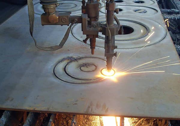
In industrial applications, metal plate thicknesses are commonly below 50mm. Within this range, conventional plasma arc cutting often produces cuts with a larger upper edge and a smaller lower edge. This discrepancy can reduce the size accuracy of the incision and necessitate additional processing work.
When using oxygen and nitrogen plasma arc cutting for materials like carbon steel, aluminum, and stainless steel, the following observations can be made:
The primary cause of angle error is attributed to the uneven heat input of the plasma jet on the cutting surface. The plasma arc energy release is more concentrated in the upper part of the incision compared to the lower part. This energy release imbalance is influenced by several process parameters, including the degree of plasma arc compression, cutting speed, and nozzle-to-workpiece distance.
Increasing the compression degree of the arc can extend the high-temperature plasma jet, forming a more uniform high-temperature area. This also increases the jet speed, which can reduce the width difference between the upper and lower edges of the incision. However, excessive compression of conventional nozzles can lead to double arcs, which not only consume electrodes and nozzles but also degrade the quality of the incision and potentially halt the cutting process.
Additionally, excessive cutting speed and nozzle height can exacerbate the width difference between the upper and lower edges of the incision. Therefore, careful optimization of these parameters is crucial to achieve high-quality cuts with minimal angle error and width discrepancy.
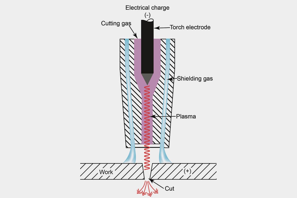
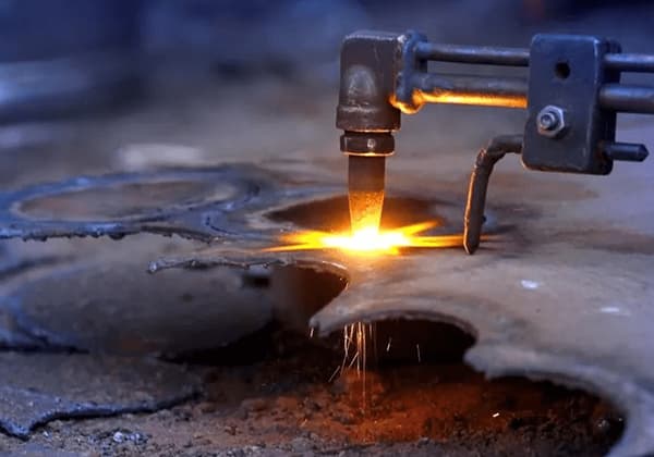
The process involves creating an electrical channel of superheated, electrically ionized gas (plasma) from the plasma cutter through the workpiece, thereby cutting it. The parameters for plasma cutting can vary based on the type of plasma gas and the cutting current used. Below are the optimized parameters for cutting low-carbon steel using different plasma gases:
| Select gas | Set cutting airflow | Material thickness | Arc voltage | Distance from cutting torch to workpiece | Cutting speed | Initial piercing height | Piercing delay | |||
| Plasma | Protective gas | Plasma | Protective gas. | mm | Voltage | mm | mm/min | mm | Coefficient % | Second |
| Air | Air | 72 | 35 | 3 | 136 | 3.1 | 6000 | 6.2 | 200 | 0.1 |
| 4 | 137 | 3.1 | 4930 | 6.2 | 200 | 0.2 | ||||
| 6 | 138 | 3.6 | 3850 | 7.2 | 200 | 0.3 | ||||
| 10 | 142 | 4.1 | 2450 | 8.2 | 200 | 0.5 | ||||
| 12 | 144 | 4.1 | 2050 | 8.2 | 200 | 0.5 | ||||
| 15 | 150 | 4.6 | 1450 | 9.2 | 200 | 0.8 | ||||
| 20 | 153 | 4.6 | 810 | 10.5 | 230 | 1.2 | ||||
| 25 | 163 | 4.6 | 410 | Start from the edge | ||||||
| 32 | 170 | 5.1 | 250 | |||||||
| Select gas | Set cutting airflow | Material thickness | Arc voltage | Distance from cutting torch to workpiece | Cutting speed | Initial piercing height | Piercing delay | |||
| Plasma | Protective gas | Plasma | Protective gas | mm | Voltage | mm | mm/min | mm | Coefficient% | Second |
| Oxygen | Air | 65 | 48 | 3 | 128 | 2.5 | 6500 | 5.0 | 200 | 0.1 |
| 4 | 129 | 2.8 | 5420 | 5.6 | 200 | 0.2 | ||||
| 6 | 130 | 2.8 | 4000 | 5.6 | 200 | 0.3 | ||||
| 10 | 134 | 3.0 | 2650 | 6.0 | 200 | 0.3 | ||||
| 12 | 136 | 3.0 | 2200 | 6.0 | 200 | 0.5 | ||||
| 15 | 141 | 3.8 | 1650 | 7.6 | 200 | 0.7 | ||||
| 43 | 20 | 142 | 3.8 | 1130 | 7.6 | 200 | 1.0 | |||
| 25 | 152 | 4.0 | 675 | 8.0 | 200 | 1.5 | ||||
| 32 | 155 | 4.5 | 480 | Start from the edge | ||||||
| 38 | 160 | 4.5 | 305 | |||||||
By adhering to these parameters and considerations, you can achieve efficient and high-quality cuts when working with low-carbon steel using plasma cutting technology.

As the founder of MachineMFG, I have dedicated over a decade of my career to the metalworking industry. My extensive experience has allowed me to become an expert in the fields of sheet metal fabrication, machining, mechanical engineering, and machine tools for metals. I am constantly thinking, reading, and writing about these subjects, constantly striving to stay at the forefront of my field. Let my knowledge and expertise be an asset to your business.