With the continuous development of plasma cutting technology, the utilization of CNC plasma cutting machines is becoming increasingly widespread.
The CNC plasma cutting machine is one of the primary cutting and blanking equipment used for medium and small-thickness plates. It offers numerous benefits, such as easy operation, high accuracy, high work efficiency, and low labor intensity.
It finds extensive usage across various industries, including the chemical industry, automobile industry, machinery industry, rail transit industry, among others.
When traditional cutting methods fail to cut tough materials, CNC plasma cutting machines come in handy.
In terms of cutting speed, when cutting medium and small-thickness carbon steel plate, the CNC plasma cutting speed is faster than the traditional flame cutting speed, and the cutting surface remains smooth with minimal hot deformation.
Moreover, the CNC plasma cutting method is a more cost-effective option than laser cutting.
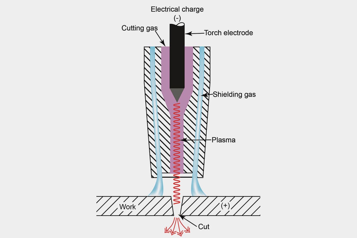
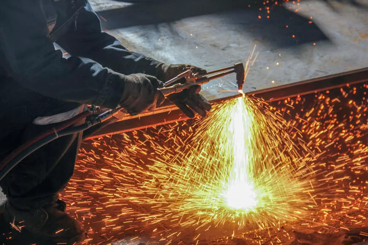
Principle of Plasma Cutting
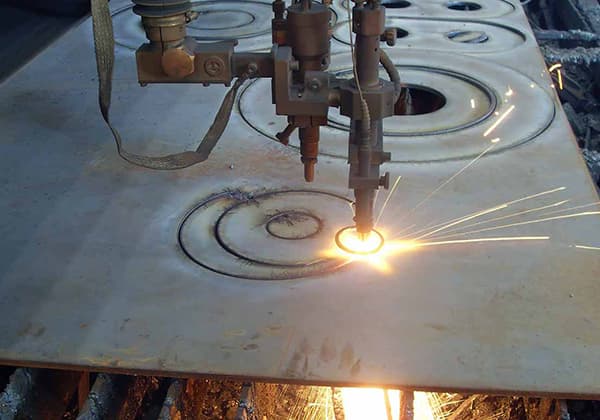
A plasma cutter operates by ionizing a mixture of gases through a high-frequency arc. This ionized gas, or plasma, is then expelled from the cutting nozzle due to the pressure of the gas.
The temperature of the plasma is extremely high, far exceeding the melting point of the material being cut.
This causes the material to melt rapidly, and the molten material is then blown away by the high-pressure gas from the nozzle. This process produces a significant amount of smoke and molten slag.
Therefore, plasma cutters require dust and slag removal systems. By using different gas mixtures, plasma can cut metals of various materials and thicknesses, especially excelling in cutting non-ferrous metals.
Choosing the Plasma Cutting Process
In the process of CNC (Computer Numerical Control) operation with a plasma cutter, programming is the initial step. The machining process follows a pre-programmed sequence.
In this programming phase, factors like cutting speed, cutting sequence, and starting point play a pivotal role in determining the quality of the cut.
Selection of the Starting Point
Ideally, the starting point for cutting should be at the edge of the sheet or within a previously cut seam. If the nozzle is too far from the material, it results in an incomplete cut, leading to unnecessary material wastage.
Conversely, if the nozzle is too close, it can cause a short circuit. This not only damages the material and affects the cutting quality but can also harm the nozzle.
Choosing the Cutting Direction
The direction of the cut should ensure that the final edge being cut is mostly separated from the main material.
If it detaches prematurely, the thin frame around the workpiece may not withstand the thermal stress from the cutting, causing the workpiece to shift during the process. This shift can lead to dimensional inaccuracies, affecting the quality of the cut.
Selecting the Cutting Sequence
During programming, to maximize material utilization, the workpiece is often nested within the sheet.
Thus, the cutting sequence dictates the order of material removal. Generally, the sequence follows the principle of cutting smaller pieces before larger ones and cutting inner contours before outer ones.
Otherwise, the stress generated during the cutting of inner contours or smaller pieces can lead to stress concentration, resulting in a scrapped workpiece.
Choosing the Cutting Speed
The selection of cutting speed is influenced by various factors, such as material type and thickness, nozzle design, cutting current, and chosen gas.
However, under the same power and conditions, a faster cutting speed results in a larger bevel on the workpiece.
Therefore, the nozzle should be perpendicular to the material during cutting to facilitate the rapid removal of slag. To ensure efficiency, the maximum cutting speed should be chosen without compromising the quality of the cut.
Optimization of the Cutting Table
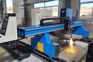
The cutting machine’s cutting table is supported by several diaphragms. As illustrated in Figure 1, the distance between two diaphragms is 110mm.
Fig. 1 CNC plasma cutting machine with cutting table
When cutting small parts, the workpiece often falls between the diaphragms, making it difficult to retrieve. The diaphragm itself is an 8mm × 190mm × 4600mm straight flat steel plate. Due to frequent cutting, the lower diaphragm accumulates a significant amount of oxide slag, which can negatively impact the quality of the cut. As a result, it requires frequent cleaning or replacement to maintain normal cutting operations.
Optimization Scheme and Implementation of Cutting Worktable
In the industry, product structures and batches are often not fixed, leading to the use of nesting to save materials. This involves matching the typesetting of large and small materials.
Currently, we need to address the issue of how to enhance the utilization rate of plasma cutting machines and prolong the service life of cutting benches through plasma bench process innovation.
To tackle this challenge, we first analyze and categorize the existing blanking products. We then select the smallest cutting part, determine its size, and design a new workbench set according to site conditions, as demonstrated in Figure 2.
Fig. 2 Table model after optimization of CNC plasma cutting machine
(1) Specific scheme.
- The platform has a size of 1500mm × 3000mm and can be combined with multiple platforms.
- The outer frame of the platform is made of 4mm plates that are folded into U-shaped parts and welded into a rectangular frame structure. This design ensures the stiffness of the frame and prevents deformation during hoisting.
- Inside the frame, there are 2-3 V-shaped parts that are folded by 4mm plates and buckled longitudinally in the frame. Additionally, a 3.5mm wide notch is opened on the longitudinal beam to facilitate the insertion of the diaphragm.
- The diaphragm is made of a 1500mm × 200mm plate with one side cut into a serrated structure.
(2) Specific implementation process.
- Design the length, width, height, and partition spacing of the cutting workbench based on the equipment parameters and the size of the required cutting parts.
- Make the cutting workbench according to the design drawing.
- All cutting table parts are cut out at once using a CNC cutting machine, resulting in accurate sizes and convenient replacement of the diaphragm.
- The cutting table frame is programmed and bent using a CNC bending machine, resulting in accurate positioning size and good formability.
- Assemble, weld, and construct the cutting workbench frame.
- Insert the diaphragm into the cutting table.
- Place the cutting table on the original cutting table. When cutting, place the material on the movable cutting table for cutting, as shown in Figure 3.
Fig. 3 Physical drawing of worktable after optimization of CNC plasma cutting machine
Path Optimization in the Cutting Process
During the cutting process, there is relative movement between the machined part and the remaining material due to the thermal expansion and cold contraction effect of the plate.
The relative movement can be categorized into three situations based on the difference between the weight of the machined part and the weight of the remaining material:
- When the weight of the machined part is greater than the weight of the remaining material, the machined part remains stationary while the remaining material moves relative to the platform. This does not affect the size of the machined part.
- When the weight of the machined part is less than the weight of the remaining material, the machined part moves relative to the platform while the remaining material remains stationary. This results in a certain deviation in the machined part.
- When the weight of the machined part is equal to the weight of the remaining material, both the machined part and the remaining material may move relative to the platform, which can affect the size of the machined part.
Practice has shown that the dimensional error of machined parts typically ranges from 0.3 to 4 mm due to the relative movement of the machined part or the remaining material with respect to the platform.
The Cutting Path on One Side of the Workpiece
The selection of a reasonable cutting process can result in varying degrees of deformation during the CNC plasma cutting process.
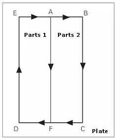
When cutting the plate depicted in Figure 4, if point A is chosen as the starting point for the arc, the cutting sequence and direction should be: A → D → C → B → A (see Figure 4a).
Fig. 4 Cutting path and deformation of one side of the workpiece
When the AD section is cut and the DC section is processed, the narrow residual material in the DC section is linearly elongated due to the high temperature during cutting, causing the CB section to deflect outward.
After cutting, the size of the DC section is reduced by δ (as shown in Fig. 4b). The value of δ is proportional to the size of the DC section.
If the cutting sequence A → B → C → D → A is selected, the workpiece can be separated from the motherboard through DA, which can effectively reduce cutting deformation.
Deformation Control of Slender Parts
When cutting the slender parts shown in Figure 5, following the sequence A→B→C→D→A, the expansion of the BC section can prevent the expansion of the CD section when cutting the DA section.
Fig. 5 Cutting of slender parts
After the cutting and cooling process, the DA section should experience more shrinkage than the BC section to bend the workpiece towards the DA side.
The amount of side bending δ depends on the length-width ratio Y/X of the machined part. As the length-width ratio increases, so does the side bending amount δ.
When using two pairs for cutting, as shown in Figure 6, choose point A as the starting point of the arc, and follow the cutting direction and sequence: A → B → C → D → E → A → F.
Fig. 6 Paired cutting of two slender parts
When working on the DE section, removing it from the motherboard is comparable to decreasing the length-width ratio of the workpiece by half, resulting in a reduction of the side bending amount.
While cutting the AF section, the expansion and contraction on both sides of the workpiece are uniform, leading to a considerable reduction in the δ deformation of slender parts.
Cutting Technology of Special-shaped Parts
For the cutting of special parts (Fig. 7), the following cutting processes can be selected according to the above processing methods and different special-shaped parts.
Fig. 7 Cutting of special parts
(1) For concave parts, two paired cutting methods are adopted.
First cutting the inner edge, then cutting the outer edge, and finally separating the two parts from the outside to the inside.
The cutting sequence is shown in Fig. 8.
The inner edge: A1 → B1 → C1 → D1 → A1;
Outside: A → B → C → D → A, and finally E → F, H → G.
Fig. 8 Paired cutting of two concave parts
(2) For offset hollow parts, two pieces shall be cut in pairs, and finally, the two pieces shall be separated.
The cutting sequence is shown in Fig. 9.
The inner side: A1 → B1 → C1 → D1 → A1, A2 → B2 → C2 → D2 → A2
The outer side: A → B → C → D → A, and finally E → F.
Fig. 9 Paired cutting of two offset hollow parts
Optimization of Plasma Equipment
During the cutting process with air plasma, the top of the electrode core undergoes a high-temperature oxidation reaction with the oxygen in the air, hence electrode wear is inevitable.
The lifespan of an electrode is related to the number of arc starts; under the same conditions, the more arc starts, the more the electrode wears. Frequent arc starts significantly reduce the lifespan of the electrode.
However, the continuous cutting process reduces the number of starting points for non-common edge workpieces, making shared-edge workpieces have only one cutting start point.
This reduces the number of arc starts during cutting, thereby enhancing the lifespan of the electrode.
Conclusion
The process innovation has several beneficial effects. Firstly, it greatly improves the utilization rate of the plasma cutting machine. Secondly, the replacement of the worktable diaphragm is convenient and reduces the replacement rate by half, thus reducing the replacement cost. Thirdly, it can meet the cutting requirements of small parts.
Currently, this process innovation is widely used in the blanking of steel structures for railway passenger cars. As each car has many small parts that need to be cut and blanked, this innovation improves work efficiency and saves costs.
When using plasma cutting, the following problems should be considered: the deformation law and influence of cutting parts of CNC plasma cutting machines should be analyzed. Before cutting, appropriate plate leveling treatment should be carried out, and the plate should be fixed to prevent the movement of machined parts during cutting.
When compiling the cutting program, a reasonable cutting process should be selected to separate the maximum size surface of the workpiece from the motherboard. For cutting slender or special-shaped parts, control methods such as two-piece paired cutting can effectively prevent or reduce the deformation of the cutting parts.
Compared to flame cutting, CNC plasma cutting is superior in terms of cutting quality and benefits in the processing industry. It can cut all kinds of metals with different working gases, especially non-ferrous metals.