Gas Welding and Cutting: Choosing the Right Flame and Parameters
What’s the secret behind flawless welds and precise cuts in gas welding and cutting? It all comes down to the flame. This article explores the different types of flames used…
Have you ever wondered how gas welding works and why it’s so crucial in mechanical engineering? This article breaks down the principles, types of gas flames, and materials used in gas welding. By the end, you’ll understand how different gases and welding wires impact the quality and safety of welding processes.
(1) Oxygen
Oxygen is a gas at normal temperature and pressure, with the molecular formula O2.
Oxygen itself is not combustible, but it can help other combustible substances to burn, and has a strong combustion-promoting effect.
The purity of oxygen has a direct impact on the quality, productivity, and oxygen consumption of gas welding and gas cutting.
The higher the purity of oxygen, the better the quality of gas welding and gas cutting.
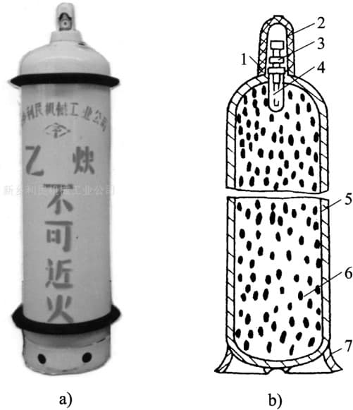
(2) Acetylene
Acetylene is a colorless hydrocarbon compound with a special odor, obtained by the interaction of calcium carbide and water, with the molecular formula C2H2.
Acetylene is a combustible gas, and the flame temperature generated when it is mixed with air is 2350°C, while the flame temperature generated when it is mixed with oxygen and burned is 3000-3300°C.
Acetylene is a dangerous gas that is explosive under certain pressure and temperature conditions.
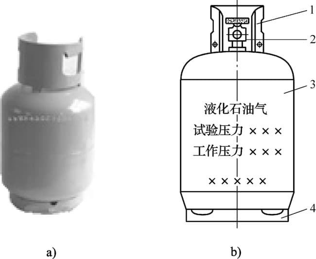
(3) Liquefied Petroleum Gas (LPG)
Liquefied Petroleum Gas is mainly composed of hydrocarbons such as propane (C3H8), butane (C4H10), and propylene (C3H6).
It exists as a gas under normal pressure, but can be liquefied at a pressure of 0.8-1.5 MPa for storage and transportation, hence the name Liquefied Petroleum Gas.
Like acetylene, LPG is explosive when mixed with air or oxygen, but it is much safer than acetylene.
(1) Oxy-Acetylene Flame.
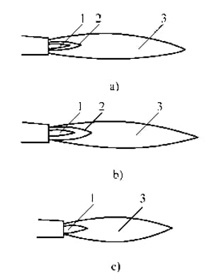
The structure and shape of Oxy-Acetylene flame:
a) Neutral flame b) Carburizing flame c) Oxidizing flame
1- Flame center 2- Inner flame 3- Outer flame
| Flame type | Mixing ratio of oxygen and acetylene | Maximum flame temperature/℃ | Flame characteristics |
| Neutral flame | 1.1-1.2 | 3050-3150 | Oxygen and acetylene are fully burned, with neither excess oxygen nor excess acetylene. The flame core is bright, with clear contours, and the inner flame has a certain degree of reducibility |
| Carbonization flame | <1.1 | 2700-3000 | Acetylene is surplus, and there is free carbon and hydrogen in the flame, which has a strong reduction effect and also has a certain carbon effect. The entire flame of carbonization flame is longer than that of neutral flame |
| Oxide flame | >1.2 | 3100-3300 | There is an excess of oxygen in the flame, which has strong oxidizing properties. The entire flame is short, and the layers of the inner and outer flames are unclear |
The structure of the Oxygen-Liquefied Petroleum Gas flame is basically the same as that of the Oxy-Acetylene flame, and also can be classified into oxidizing flame, carburizing flame, and neutral flame.
The flame center undergoes partial decomposition reactions, but with fewer decomposition products.
The inner flame is not as bright as acetylene and appears slightly bluish, while the outer flame is clearer and longer than the Oxy-Acetylene flame.
Due to the higher ignition point of Liquefied Petroleum Gas, it is more difficult to ignite than acetylene and requires a direct flame for ignition.
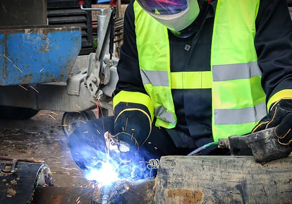
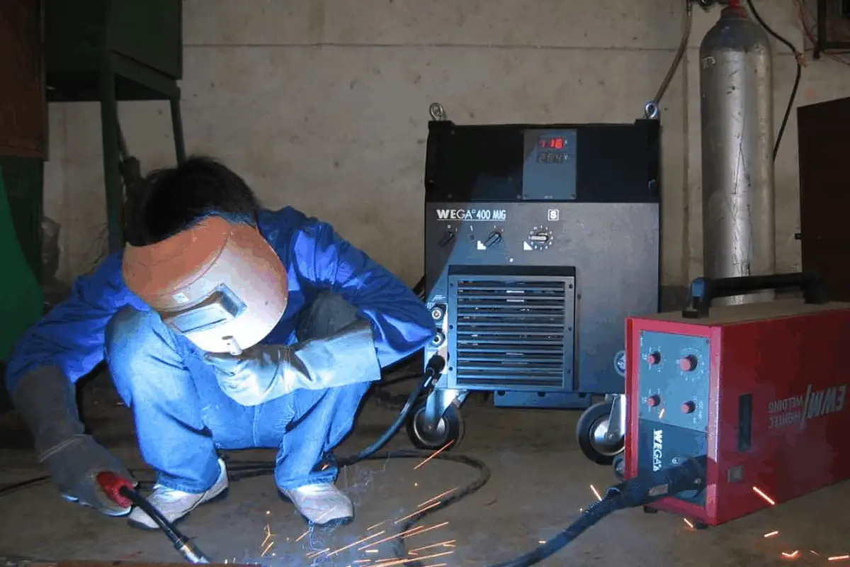
(1) Principles of Gas Welding.
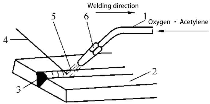
1 – Gas mixing tube; 2 – Workpiece; 3 – Weld joint; 4 – Filler wire; 5 – Gas welding flame; 6 – Welding torch.
(2) Characteristics and Applications of Gas Welding
The advantages of gas welding are that it requires simple equipment, is easy to operate, has low costs, and has strong adaptability. It can be used in places without electricity supply for convenient welding.
The disadvantages of gas welding are that the flame temperature is low, heating is scattered, the heat-affected zone is wide, the workpiece is easily deformed and overheated, and the quality of gas welding joints is not as easy to ensure as with electrode arc welding.
The productivity is low, and it is difficult to weld thick metals. It is also challenging to achieve automation.
(1) Gas Welding Wire
Table 3-2 Grade and Usage of Common Steel Welding Wires.
| Carbon structural steel welding wire | Alloy structural steel welding wire | Stainless steel welding wire | |||
| Grade | purpose | Grade | purpose | Grade | Purpose: |
| H08 | Welding of general low-carbon steel structures | H10Mn2 | Same purpose as HO8Mn | H03Cr21Ni10 | Welding ultra-low carbon stainless steelJoining 18-8 type stainless steel |
| H08Mn2Si | |||||
| H08A | Welding of important low and medium carbon steel and certain low alloy steel structures | H10Mn2MoA | Welding ordinary low alloy steel | H06Cr21Ni10 | Welding 18-8 type stainless steel |
| H08E | Same purpose as H08A, with good process performance | H10Mn2MoVA | Welding ordinary low alloy steel | H08Cr21Ni10 | Welding 18-8 type stainless steel |
| H0SMn | Welding important carbon steel and ordinary low alloy steel structures, such as boilers, pressure vessels, etc | HO8CrMoA | Welding of chromium molybdenum steel and other H | O8Cr19Ni10Ti | Welding high-strength structural steel and heat-resistant alloy steel, etc. |
| H08MnA | Same purpose as H08Mn, but with good process performance | H18CrMoA | Welded structural steel, such as chromium molybdenum steel, chromium manganese silicon steel, etc | H12C24Ni13 | Welding high-strength structural steel and heat-resistant alloy steel, etc. |
| H15A | Welding medium strength workpieces | H30CrMnSiA | Welding chromium manganese silicon steel | H12Cr26Ni21 | Welding high-strength structural steel and heat-resistant alloy steel, etc. |
| H15Mn | Welding medium strength workpieces | H10CrMoA | Welding heat-resistant alloy steel | ||
| Welding wire model | Welding wire grade | name | Main chemical components | Melting point/℃ | purpose |
| SCu1898 (CuSnl) | HS201 | Pure copper welding wire | ω(Sn) ≤ 1.0% ω(Si)=0.35% -0.5% ω(Mn)=0.35% -0.5%, the rest are Cu | 1083 | Gas welding, argon arc welding and plasma arc welding of pure copper |
| SCa6560 (CuSi3Mn) | HS211 | Bronze welding wire | ω(Si)=2.8%~4.0% ω(Mn) ≤ 1.5%, the rest are Cu | 958 | Gas welding, ammonia arc welding and plasma arc welding of bronze |
| SCu4700 (CuZn40Sn) | HS221 | Brass welding wire | ω(Cu)=57% -61% ω(Sn)=0.25% -1.0%, the rest are Zn | 886 | Gas welding, argon arc welding and plasma arc welding of brass |
| SCu6800 (CuZn40Ni) | HS222 | Brass welding wire | ω(Cu)=56% -60% ω(Sn)=0.8% -1.1% ω(Si)=0.05% -0.15% ω(Fe)=0.25% -1.20% ω(Ni)=0.2% -0.8% The rest are Zn | 860 | |
| SCu6810A (CuZn40SnSi) | HS223 | Brass welding wire | ω(Cu)=58% -62% ω(Si)=0.1% -0.5% ω(Sn) ≤ 1.0. The rest are Zn | 905 |
Table 3-4: Common Types, Grades, Chemical Compositions, and Applications of Aluminum and Aluminum Alloy Welding Wires.
| Welding wire model | Welding wire grade | name | Main chemical components | Melting point/℃ | purpose |
| SAl1450 (A199.5Ti) | HS301 | Pure aluminum welding wire | ω(Al)≥99.5% | 660 | Gas welding and argon arc welding of pure aluminum |
| SAl4043 (AIS) | HS311 | Aluminum silicon alloy welding wire | ω(Si)=4.5% -6%, others are Al | 580-610 | Welding of aluminum alloys other than aluminum magnesium alloys |
| SAB103 (AIMnl) | HS321 | Aluminum manganese alloy welding wire | ω(Mn)=1.0% -1.6%, the rest are Al | 643-654 | Gas welding and ammonia arc welding of aluminum manganese alloy |
| SAl5556 (AlMg5 MnlTi | HS331 | Aluminum magnesium alloy welding wire | ω(Mg)=4.7%~5.5% ω(Mn)=0.3% -1.0% ω(Ti)=0.05% -0.2 The rest are Al | 638-660 | Welding of aluminum magnesium alloys and aluminum zinc magnesium alloys |
Table 3-5: Types, Grades, Chemical Compositions, and Applications of Cast Iron Gas Welding Wires.
| Welding wire model and grade | Chemical composition/% | purpose | ||||
| ω (C) | ω (Mn) | ω (S) | ω (P) | ω (Si) | ||
| RZC-I | 3.20-3.50 | 0.6-0.75 | ≤0.10 | 0.5-0.75 | 2.7-3.0 | Welding repair of gray cast iron |
| RZC-2 | 3.5-4.5 | 0.3-0.8 | ≤0.1 | ≤0.05 | 3.0-3.8 | |
| HS401 | 3.0~4.2 | 0.3-0.8 | ≤0.08 | ≤0.5 | 2.8-3.6 | |
| HS402 | 3.0-4.2 | 0.5-0.8 | ≤0.05 | ≤0.5 | 3.0-3.6 | Welding repair of ductile iron |
(2) Gas Welding Flux
Table 3-6: Grades, Performance, and Applications of Commonly Used Gas Welding Fluxes.
| Welding Flux Grade | name | Basic Performance | Application |
| CJ101 | Stainless Steel and Heat-resistant Steel Gas Welding Flux | It has a melting point of 900℃ and has good wetting properties, which can prevent the melted metal from being oxidized. The slag is easy to remove after welding. | Used for gas welding of stainless steel and heat-resistant steel |
| CJ201 | Cast Iron Gas Welding Flux | It has a melting point of 650℃ and has an alkaline reaction. It has deliquescence and can effectively remove silicates and oxides generated during the gas welding of cast iron. It also has the function of accelerating the melting of metals. | Used for gas welding of cast iron parts |
| CJ301 | Copper Gas Welding Flux | It is a boron-based salt, which is prone to deliquescence and has a melting point of about 650℃. It has an acidic reaction and can effectively dissolve copper oxide and cuprous oxide. | Used for gas welding of copper and copper alloys |
| CJ401 | Aluminum Gas Welding Flux | The melting point is about 560℃, it has an acidic reaction and can effectively destroy the aluminum oxide film. However, due to its strong hygroscopicity, it can cause corrosion of aluminum in the air. After welding, the slag must be cleaned thoroughly. | Used for gas welding of aluminum and aluminum alloys |
The gas welding flux grades are represented by CJ followed by three digits, and the coding method is: CJxxx.


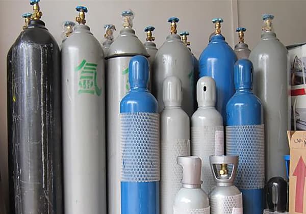
The composition of gas welding equipment:
1. Oxygen Cylinder
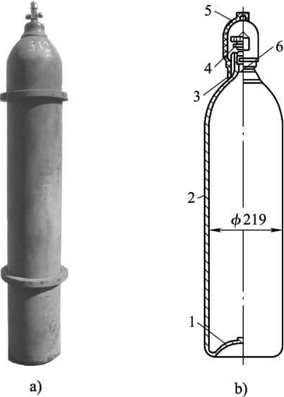
2. Acetylene Cylinder
3. Liquefied Petroleum Gas Cylinder (LPG Cylinder)
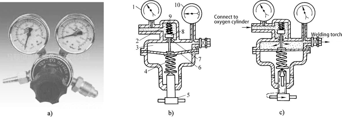
4. Pressure Regulator
(1) Functions and Types of Pressure Regulators
The function of a pressure regulator is to reduce the high-pressure gas in the cylinder to the required pressure for operation and maintain a stable pressure during operation.
Pressure regulators can be classified into oxygen pressure regulators, acetylene pressure regulators, liquefied petroleum gas pressure regulators, etc. according to their uses.
According to their structures, they can be classified into single-stage and two-stage regulators. According to their working principles, they can be classified into direct-acting and reverse-acting regulators.
(2) Oxygen Regulator
(3) Acetylene Regulator

(4) Liquefied Petroleum Gas Regulator
The function of the Liquefied Petroleum Gas Regulator is to reduce the pressure in the gas cylinder to the working pressure and stabilize the output pressure to ensure even gas supply.
Generally, regulators for household use can be slightly modified to be used for cutting general thickness of steel plate.
In addition, the Liquefied Petroleum Gas Regulator can also be used directly with a propane regulator.
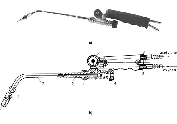
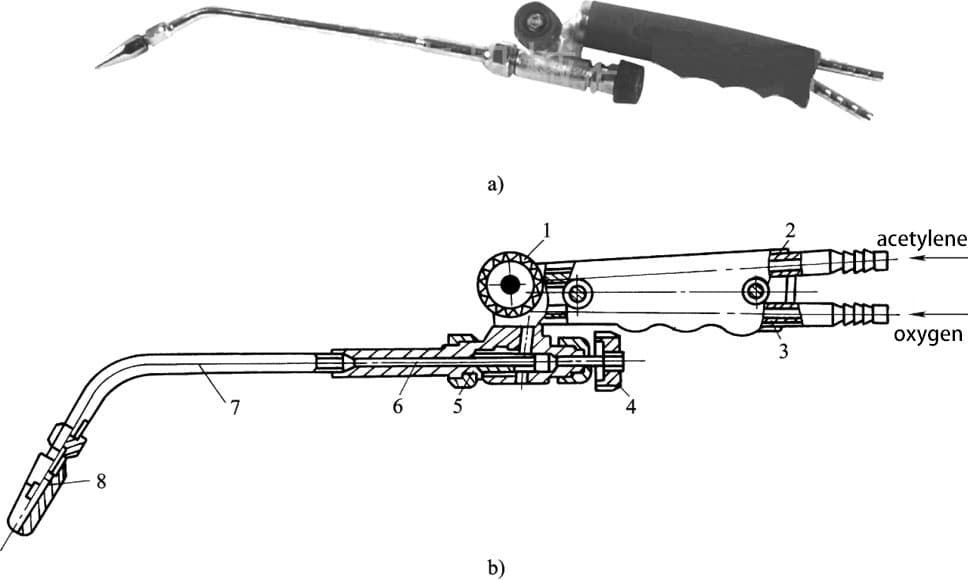
5. Welding Torch
(1) Functions and Types of Welding Torch
The function of a welding torch is to mix combustible gas and oxygen in a certain proportion and spray them out at a certain speed for combustion, thereby generating a flame with a certain energy, composition, and stable shape.
According to the different ways of mixing combustible gas and oxygen, welding torches can be divided into injection-type welding torches (also known as low-pressure welding torches) and equal-pressure welding torches.
(2) Structure and Principle of Injection-Type Welding Torch
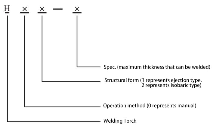
(3) Representation of Welding Torch Model
The welding torch model is composed of the Pinyin letter “H” followed by the serial number and specification that represents the structural form and operating mode.
6. Gas Hose
The gases in the oxygen cylinder and acetylene cylinder need to be transported to the welding or cutting torch through rubber hoses.
According to the national standard “Rubber hose for gas welding, cutting, and similar operations,” the oxygen hose is blue and the acetylene hose is red.
The length of the hose connected to the welding torch should not be less than 5 meters, but if it is too long, it will increase the resistance to gas flow.
Generally, a length of 10 to 15 meters is recommended. The rubber hose used for the welding torch must not be contaminated with oil, leak gas, and it is strictly prohibited to interchange hoses between different gases.
7. Other Auxiliary Tools
(1) Welding Goggles

(2) Ignition Gun
A pistol-style ignition gun is the safest and most convenient way to ignite the welding torch.
In addition, welding tools also include cleaning tools such as wire brushes, hammers, and files; tools for connecting and closing gas passages, such as pliers, wire, hose clamps, wrenches, and cleaning needles for welding nozzles.
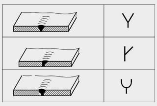
1. Form of Joint
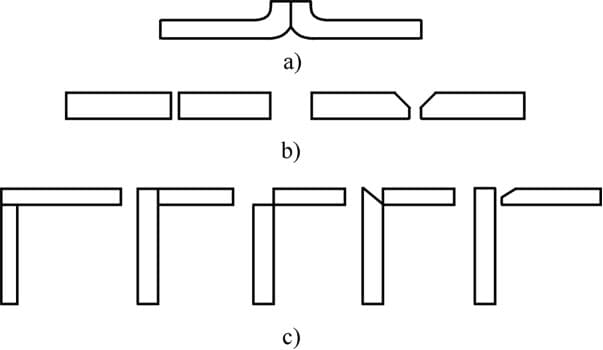
Table 3-7 Shape and Dimensions of Lap Joint and Butt Joint for Low Carbon Steel
| Joint form | Plate thickness/mm | Curled and blunt edges/mm | Gap/mm | Groove angle | Welding wire diameter/mm |
| Crimping joint | 0.5-1.0 | 1.5-2.0 | no need | ||
| I-shaped groove butt joint | 1.0-5.0 | 1.0-4.0 | 2.0-4.0 | ||
| V-groove butt joint | >5.0 | 1.5-3.0 | 2.0-4.0 | Left welding method 80 °, right welding method 60 ° | 3.0-6.0 |
2. Gas Welding Parameters
(1) Welding Wire Type, Grade, and Diameter
| Weldment thickness/mm | 1-2 | 2-3 | 3-5 | 5-10 | 10-15 |
| Welding wire diameter/mm | 1-2 or without welding wire | 2-3 | 3-3.2 | 3.2-4 | 4-5 |
(2) Gas Welding Flux
The selection of gas welding flux should be based on the composition and properties of the workpiece. Generally, carbon structural steel does not require gas welding flux for gas welding.
However, stainless steel, heat-resistant steel, cast iron, copper and copper alloys, and aluminum and aluminum alloys require the use of gas welding flux for gas welding.
(3) Properties and Efficiency of Flames
1) Properties of Flames
2) Efficiency of Flames
Table 3-9 Selection of Gas Welding Flames for Various Metal Materials.
| Material type | Flame type | Material type | Flame type |
| Low and medium carbon steel | Neutral flame | Aluminum nickel steel | Neutral flames or slightly more acetylene neutral flames |
| Low alloy steel | Neutral flame | Manganese steel | Oxide flame |
| Purple copper | Neutral flame | Galvanized iron sheet | Oxide flame |
| Aluminum and aluminum alloys | Neutral flame or slightly carbonized flame | High speed steel | Carbonization flame |
| Lead, tin | Neutral flame | Hard alloy | Carbonization flame |
| Bronze | Neutral flame or slight oxidation flame | High carbon steel | Carbonization flame |
| Stainless steel | Neutral flame or slightly carbonized flame | Cast iron | Carbonization flame |
| Brass | Oxide flame | Nickel | Carbonization flame or neutral flame |
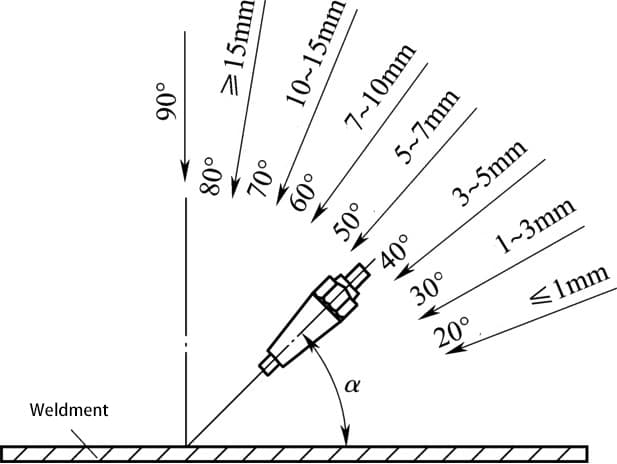
(4) Nozzle Size and Tilt Angle of Welding Torch
The nozzle is the outlet for the oxy-acetylene mixed gas. Each welding torch is equipped with a set of nozzles of different diameters. When welding thicker workpieces, a larger nozzle should be selected.
Table 3-10 Selection of Nozzles for Weldments of Different Thicknesses.
| Welding nozzle number | 1 | 2 | 3 | 4 | 5 |
| Weldment thickness/mm | <1.5 | 1~3 | 2~4 | 4~7 | 7~11 |
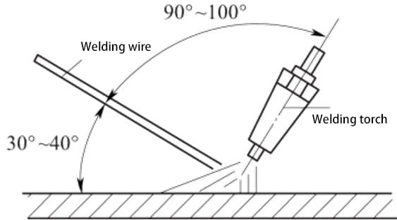
(5) Welding Direction.
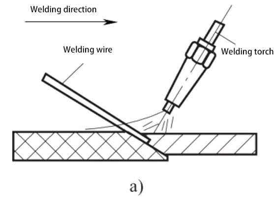
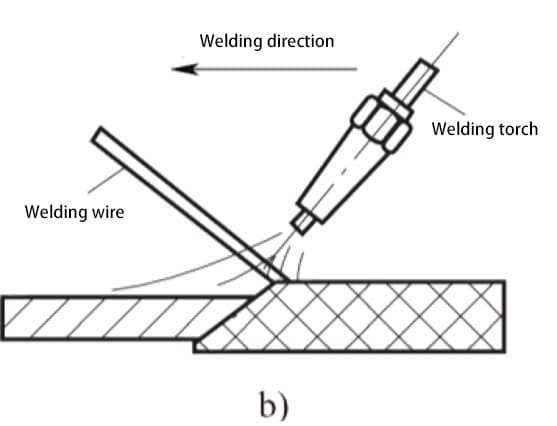
(6) Welding Speed.
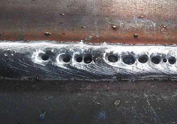
Impact of Gas Welding Parameters on Welding Quality and Weld Seam Formation.
Welding wire diameter:
Welding nozzle number:
Surface condition of base material:
Distance from welding nozzle end to weldment:
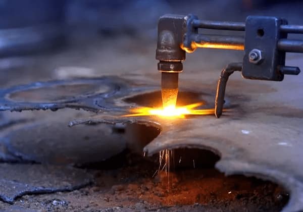
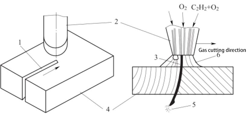
1. Principle of Gas Cutting
Gas cutting is a cutting method that utilizes the thermal energy of a gas flame to preheat the cutting area of a workpiece to the ignition temperature, and then sprays a high-speed cutting oxygen stream, causing it to burn and release heat, thereby achieving the cutting process.
(1) Advantages of Gas Cutting:
High cutting efficiency, cutting speed for steel is faster than other mechanical cutting methods.
For cross-sectional shapes and thicknesses that are difficult to cut using mechanical methods, oxy-fuel flame cutting is more economical.
Investment in gas cutting equipment is lower than that of mechanical cutting equipment, and gas cutting equipment is lightweight and can be used for field operations.
When cutting small arcs, the cutting direction can be quickly changed.
Both manual and mechanical cutting can be performed using gas cutting.
(2) Disadvantages of Gas Cutting:
Low cutting size accuracy, with dimensional tolerances inferior to those obtained by mechanical methods.
The preheating flame and discharged hot slag pose risks of fire, equipment damage, and operator burns.
During cutting, appropriate dust control and ventilation devices are required to control the combustion of gases and oxidation of metals.
Material cutting is limited.
(3) Applications of Gas Cutting
Due to its high efficiency, low cost, and simple equipment, gas cutting is widely used for cutting steel plates and parts with various complex shapes in various positions. It is widely used in cutting steel plates, opening weld bevels, and cutting casting risers, with cutting thicknesses of up to 300mm or more.
1. Conditions for Gas Cutting
(1) The ignition point of the metal in oxygen should be lower than its melting point. This is the most basic condition for the normal process of oxy-fuel cutting.
(2) The melting point of the metal oxide produced during the oxy-fuel cutting process must be lower than the melting point of the metal itself, and it must have good fluidity so that the oxide can be blown away from the kerf in a liquid state.
Table 3-11 Melting Points of Common Metal Materials and Their Oxides.
| Metallic materials | Melting point of metal/℃ | Melting point of oxide/℃ |
| pure iron | 1535 | 1300-1500 |
| mild steel | 1500 | 1300~1500 |
| high carbon steel | 1300~1400 | 1300-1500 |
| aluminum | 1200 | 1300~1500 |
| copper | 1084 | 1230-1336 |
| lead | 327 | 2050 |
| aluminium | 658 | 2050 |
| chromium | 1550 | 1990 |
| nickel | 1450 | 1990 |
| zinc | 419 | 1800 |
(3) Combustion of metals in the cutting oxygen jet should be an exothermic reaction. This is because the result of an exothermic reaction is the production of a large amount of heat from the combustion of the upper metal layer, which plays a preheating role for the lower metal layer.
(4) The thermal conductivity of the metal should not be too high. Otherwise, the heat released by oxidation during the preheating flame and gas cutting process will be conducted and dissipated, making it impossible for gas cutting to start or stop halfway.
2. Gas Cutting Properties of Common Metals
(1) Low carbon steel and low alloy steel can meet the requirements so that gas cutting can be carried out smoothly.
(2) Cast iron cannot be cut with oxy-fuel cutting.
(3) High chromium steel and chromium-nickel steel will produce high-melting chromium oxide and nickel oxide (about 1990℃), making gas cutting difficult.
(4) Copper, aluminum and their alloys have ignition points higher than their melting points and good thermal conductivity, making gas cutting difficult.
1. Cutting Torch
(1) Function and Classification of Cutting Torch
The function of a cutting torch is to mix combustible gas and oxygen in a certain proportion and manner to form a preheating flame with a certain energy and shape, and to spray cutting oxygen in the center of the preheating flame for gas cutting.
Cutting torches can be divided into two types: injection-type cutting torch and equal-pressure cutting torch according to the different ways of mixing combustible gas and oxygen.
According to the different types of combustible gas, they can be divided into acetylene cutting torches, liquefied petroleum gas cutting torches, and so on.
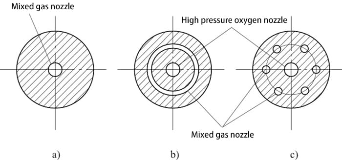
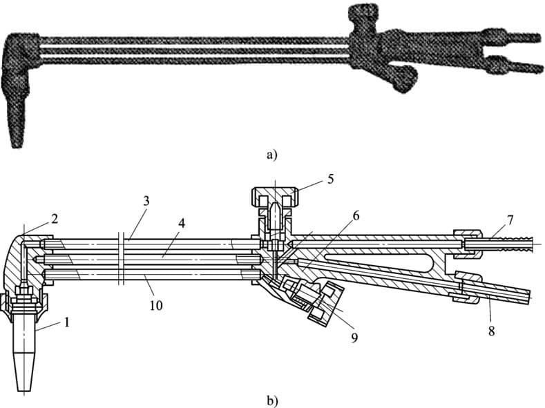
(2) Structure and Principle of Injection-type Cutting Torch
Structure of Injection-type Cutting Torch.
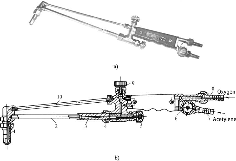
During gas cutting, first open the preheating oxygen regulator valve and acetylene regulator valve, and ignite to produce a preheating flame to preheat the workpiece.
When the workpiece is preheated to the ignition point, open the cutting oxygen regulator valve.
At this time, the high-speed cutting oxygen flow through the cutting oxygen pipe and is sprayed from the center hole of the cutting nozzle to perform gas cutting.
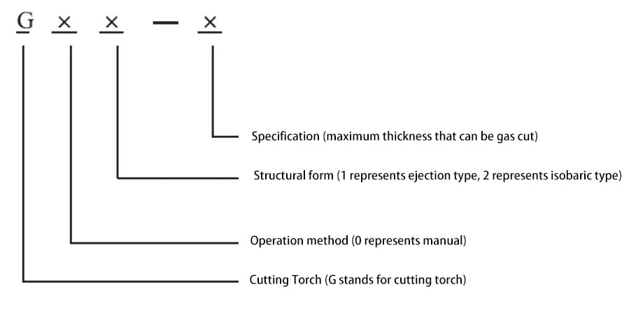
(3) Representation of Cutting Torch Model
The cutting torch model is composed of the Chinese Pinyin letter G and a number that represents the structure and operating mode, as well as the specifications.
(3) Representation method of the cutting torch model
The cutting torch model is composed of the Chinese Pinyin letter G plus a sequence of numbers and specifications that represent the structural form and operating method.
(4) Liquefied Petroleum Gas Cutting Torch
For liquefied petroleum gas cutting torches, due to the different combustion characteristics between liquefied petroleum gas and acetylene, the injector-type cutting torch used for acetylene cannot be used directly.
It is necessary to modify the cutting torch or use a special cutting nozzle for liquefied petroleum gas.
In addition to self-modification, liquefied petroleum gas cutting torches can also be purchased as specialized equipment.
(5) Equal Pressure Cutting Torch.
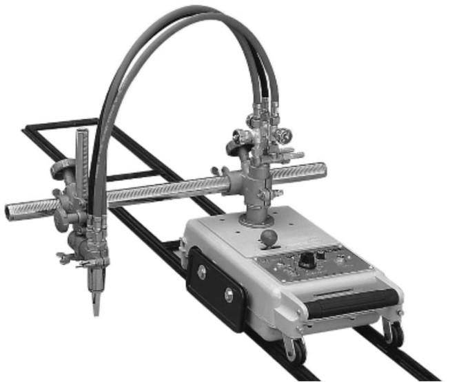
2. Gas Cutting Machine
A gas cutting machine is a mechanized equipment that replaces manual cutting torches for gas cutting.
(1) Semi-automatic Gas Cutting Machine.
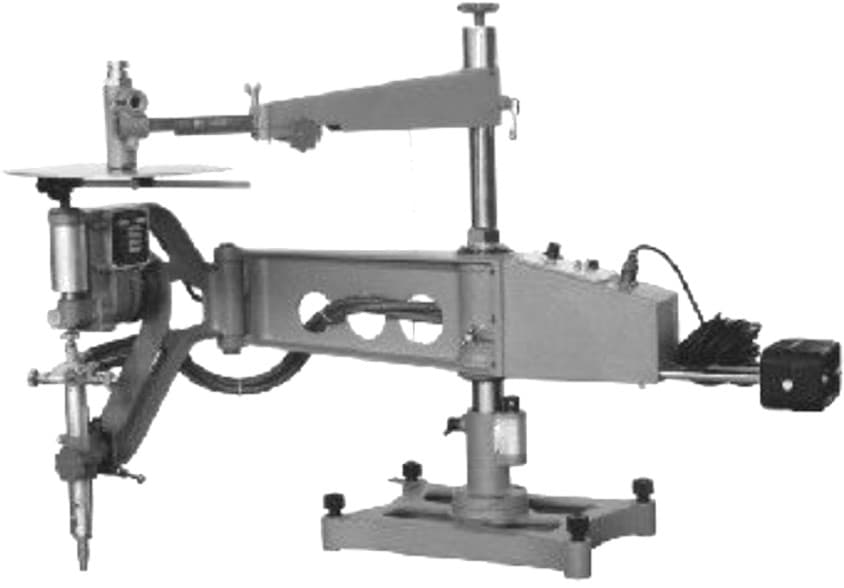
(2) Profile Gas Cutting Machine.
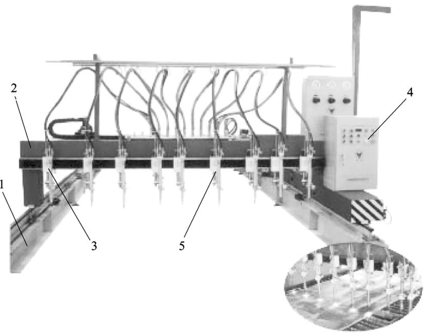
(3) CNC Gas Cutting Machine.
1. Gas Cutting Parameters.
Table 3-12: Relationship between Steel Plate Gas Cutting Thickness, Cutting Speed, and Oxygen Pressure.
| Steel plate thickness /mm | Gas cutting speed /(mn/min) | Oxygen pressure /MPa |
| 4 | 450-500 | 0.2 |
| 5 | 400-500 | 0.3 |
| 10 | 340-450 | 0.35 |
| 15 | 300-375 | 0.375 |
| 20 | 260-350 | 0.4 |
| 25 | 240-270 | 0.425 |
| 30 | 210-250 | 0.45 |
| 40 | 180-230 | 0.45 |
| 60 | 160-200 | 0.5 |
| 80 | 450-180 | 0.6 |
(2) Gas Cutting Speed
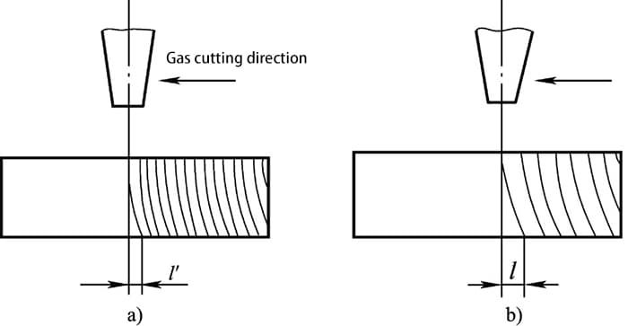
(3) Preheating Flame Properties and Efficiency.
The purpose of the preheating flame is to heat the metal cutting parts and maintain a temperature that can burn in the oxygen stream, while also causing the oxide skin on the surface of the steel to peel off and melt, making it easier for the oxygen stream to combine with the iron.
The preheating flame efficiency is expressed in terms of the amount of combustible gas consumed per hour, and should be selected based on the thickness of the cutting part.
Generally, the thicker the cutting part, the greater the preheating flame efficiency should be.
(4) Tilt Angle of Cutting Nozzle and Cutting Part.
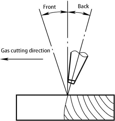
Relationship between Tilt Angle of Cutting Nozzle and Cutting Part Thickness.
| Cutting thickness /mm | <6 | 6-30 | >30 | ||
| Start cutting | After cutting through | Stop cutting | |||
| Tilt angle direction | Tilt back | Vertical | Forward tilt | Vertical | Tilt back |
| Angle of inclination | 25°-45° | 0° | 5~10° | 0° | 5°~10° |
(5) Distance between Cutting Nozzle and Cutting Part Surface.
The distance between the cutting nozzle and the cutting part surface should be determined based on the length of the preheating flame and the thickness of the cutting part, generally between 3 to 5 mm.
This heating condition is optimal and minimizes the possibility of carburization of the cutting surface.
When the cutting part thickness is less than 20mm, the flame can be longer, and the distance can be appropriately increased.
When the cutting part thickness is greater than or equal to 20mm, the flame should be shorter, and the distance should be appropriately reduced due to the slower gas cutting speed.
2. Tempering of Gas Cutting (Welding).
(1) The hose for transporting gas is too long, too narrow, or too twisted.
(2) Gas cutting (welding) time is too long or the cutting (welding) nozzle is too close to the workpiece.
(3) The end face of the cutting (welding) nozzle adheres to too many melted metal particles splattered out.
(4) Solid carbonaceous particles or other substances adhere to the gas passage inside the hose for transporting gas or the cutting (welding) torch.

As the founder of MachineMFG, I have dedicated over a decade of my career to the metalworking industry. My extensive experience has allowed me to become an expert in the fields of sheet metal fabrication, machining, mechanical engineering, and machine tools for metals. I am constantly thinking, reading, and writing about these subjects, constantly striving to stay at the forefront of my field. Let my knowledge and expertise be an asset to your business.