Are you ready to master the art of precision cutting? Discover how a CNC plasma cutter can revolutionize your metalworking projects. This guide covers everything from installation and safety precautions to operation and troubleshooting. By the end, you’ll be equipped with the knowledge to enhance your efficiency and accuracy, ensuring every cut is perfect. Dive in and learn how to optimize your CNC plasma cutting experience!
Caution Notice: Always be mindful of matters associated with the following warning signs:
Electricity may pose a risk
Standard Warning
General Tip
Before installation and initial use, please review this document thoroughly to avoid actions that could lead to property damage or personal injury. You must continuously check the system specifications and technical conditions (refer to equipment labels and associated documents).
This manual provides a brief introduction to the operation steps; for more comprehensive information, please refer to the CNC system manual, plasma power supply manual, arc voltage regulator manual, and capacitor regulator manual.
Our company reserves the right to modify the equipment configuration; the content of this book may not align with the actual situation of the equipment. Refer to the equipment for specifics.
We do not accept warranty responsibilities for equipment damage caused by non-compliance with operating requirements. In the event of equipment failure, do not replace parts on your own; please contact our company first.
1. Inspection
Be careful: Damaged or defective products must not be put into operation.
2. Transport and Storage
Pay attention: During transport and storage, it is crucial to guard against moisture. Climbing or standing on the product is not permissible, nor should heavy objects be placed on it. Special care should be taken to prevent the front panel and display screen from being bumped or scratched.
3. Installation
Be careful: The casing of the CNC system is not designed to be waterproof, hence, during installation, precautions should be taken to prevent exposure to direct sunlight and rain.
Pay attention: The installation of CNC systems should prevent the intrusion of dust, corrosive gases, conductive objects, liquids, and flammable materials. CNC systems should be installed far from flammable and explosive items and locations prone to strong electromagnetic interference. The installation of CNC systems must be secure to avoid vibration.
4. Wiring
Warning: All personnel involved in wiring or inspection must possess sufficient capability to perform this task. The electrical wires should not be damaged, subjected to compression, or energized when opening the numerical control system case.
Be careful: The voltage rating and polarity on any connector plug must adhere to the specifications in the manual. Before plugging in a connector or flipping a switch, ensure your hands are dry.
Pay attention: All connections must be correct and secure. The CNC system must be reliably grounded.
5. Commissioning and Operation
Be careful: Prior to operation, it is essential to verify the correctness of the parameter settings. Any modifications to the parameters must be within the permissible range defined by the parameter settings.
6. Usage
Warning: Do not open the device casing or secured covers during operation as this may result in personal injury and property damage.
When opening the equipment casing, the main power supply should be turned off to prevent potential personal injury and property damage.
Do not plug or unplug connectors on the machine when the main power source is on, as it may cause personal injury and permanent system damage.
Wait at least two minutes before touching or removing the circuit board and connectors after disconnecting the main power supply of the servo amplifier. This is because the residual charge in the device’s internal capacitors maintains a dangerous voltage up to two minutes after the main power supply is switched off.
First, disconnect the plasma power source before handling the cutting torch to avoid potential personal injury and property damage. When dealing with the cutting torch, be careful of burns from the high temperature of the torch nozzle.
The operator must possess the skills necessary for this job. They should have undergone safety training related to flame cutting and plasma cutting. The operator should have a basic knowledge of microcomputer operations and be familiar with the processes of flame cutting and plasma cutting.
Pay attention: Before plugging into the power source, ensure that the switch is in the off position.
Operators must not leave the equipment unattended while it is running.
Before powering up, confirm that all system wiring is correct and error-free.
When using plasma cutting, the steel plate must be leveled, and there should be no significant undulations, otherwise it will affect the cutting size accuracy and greatly reduce the lifespan of the nozzle and electrode.
7. Troubleshooting
Warning: The personnel involved in troubleshooting must possess the corresponding professional knowledge and work capabilities.
Be careful: After an alarm occurs, the malfunction must be resolved before the system can be restarted.
8. Power Supply
Pay attention: This equipment utilizes only a 380V 50 Hz main power supply. The environmental conditions for the use of the equipment must be in complete accordance with the specifications in this manual.
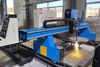
II. Equipment Installation
1. Precautions for Cutter Installation
1. After unboxing, place the plasma power source in the middle position on the left, with a wooden pad underneath. The control cabinet should be placed at the rear position on the left side of the cutter, allowing the operator to visually monitor the entire cutter and the cutting process.
2. Unpack the drag chain on the left side and place it parallel to the cutter.
3. Adjust the six foot bolts that come with the machine and level the equipment with a level meter.
4. Connect the power cord of the plasma power source to the workshop’s power supply (three-phase 380V, 50HZ), with a power of 8KW.
5. Connect the ground wire of the plasma power source to the grid frame or steel plate of the workbench.
6. Connect the power cord of the control cabinet to the workshop’s power supply (three-phase 380V, 50HZ), with a power of 3KW.
7. Properly connect the plug behind the computer on the control cabinet.
8. Install the monitor, and connect the power and signal lines.
9. Connect the inlet and outlet water pipes and fill the water until the depth in the water tank reaches 80mm.
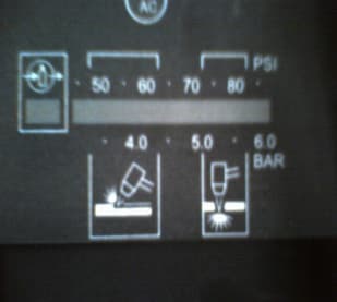
10. Connect the compressed air to the air inlet of the plasma power source using an air pipe, and adjust the air pressure to 5.0.
11. Sequentially switch on the main power, control cabinet key switch, host power, monitor, and plasma power source.
12. Operate according to the plasma power source manual, system operation manual, and user manual. Do not randomly modify the parameters set in the system when not familiar with them.
13. If the cutting quality is poor and cannot be resolved, check the electrode and nozzle of the plasma cutting torch. If damaged, they should be replaced.
2. Cable Routing Arrangement
It is recommended to use floor trench routing for the connection cables between the cutting machine body and the electrical control cabinet. This method not only protects the cables but also facilitates maintenance.
3. Mark
Mark the effective working range on the cutting table, and place the workpiece within this marked range for cutting.
4. Power Supply
This device has two power supply cables: 1. The main power supply cable for the control system, with a power of 2KW and a voltage of three-phase 380V. 2. The plasma power supply cable, with a power of 8.4KW and a voltage of three-phase 380V.
The length of the external cable from the equipment is about 15m. The main power supply cable for the control system is a 3+1 cable with a diameter of 2mm2, and the plasma power supply cable is a 4-core cable with a diameter of 6mm2.
Both cables and the air pipe slide in a circle through the overhead towing frame and descend along the factory wall to enter the main power switch cabinet, where they are connected to different switches. The control system and the plasma power source must be reliably grounded.
To avoid the effects of large power fluctuations (greater than ±10%) and possible transient interference signals, the equipment should be powered by a dedicated line (such as a separate line for CNC equipment from the low-voltage distribution room) or by adding a stabilizing device, which can reduce the impact of power quality and electrical interference.
If the equipment’s work location has a large number of sources of high-frequency interference, such as welding machines, argon arc welding machines, plasma cutting machines, high-power frequency converters, etc., a filter should be installed on the power cable of the CNC system to shield the interference.
Sudden power outages can result in the loss of cutting files and the production of waste materials; frequent sudden power outages can cause damage to the CNC system’s software or even hardware. Therefore, for locations where power outages frequently occur, it is advisable to equip the CNC system with a 500W UPS power supply.
5. Gas Source
Compressed air is used. When the air compressor (compressor flow rate 1m3/min) and the plasma power supply are used for cutting purposes, the compressor output pressure should be between 6.1-8.2Bar; a pressure lower than 5.5 Bar will seriously affect the cutting quality.
If the pressure drops below 4 Bar, the plasma power source will damage the electrode and it will be unable to work.
Use a high-pressure rubber-plastic tube with an inner diameter of φ10mm and a pressure of 2Mpa (20 Bar) for the gas pipe.
III. Cutting Operation
1. About Preparation
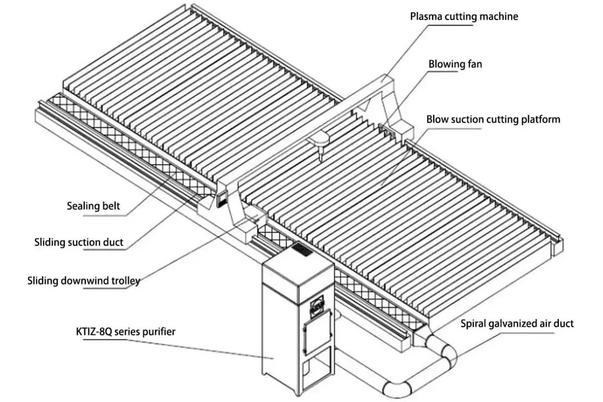
The equipment workplace must be equipped with a strong ventilation system to exhaust the smoke produced during the cutting process.
Before the equipment is powered on, make sure that all switches on the equipment are in the off position, and the rotating switch at the rear of the plasma power supply is in the horizontal position.
Figure 2-1 Plasma power supply switch (left side is the ON position)
1. Connect the main power switch cabinet to power up the two-way cable.
2. Set the circuit breaker in the equipment electrical cabinet to the ON position.
3. Use the key switch to turn on the system control power, the main interface should appear on the display.
4. Next, rotate the rotary switch at the back of the plasma power supply 90° to the vertical position, at which point the power indicator light on the front of the plasma power supply should be on.
5. Start the air compressor (compressor flow rate 1m3/min), adjust the air compressor pressure control switch to maintain the compressor output pressure between 6.1-8.2Bar. If the pressure falls below 6.1Bar, the cutting pressure will decrease, resulting in unstable cutting quality. If the pressure exceeds 8.3Bar, it can damage the air filter on the plasma power supply.
Adjust the pressure regulator knob on the plasma power supply to keep the pressure between 5.5-6.0Bar. Rotate the plasma power supply current adjustment/gas test knob to the gas test position and confirm that the pressure does not fall below 5Bar. When the pressure falls below 5Bar, it will severely affect the cutting quality and may even cause the plasma power supply to stop working.
If the working environment can’t ensure clean air supply, a multi-stage combined filtration system should be installed before the plasma power supply. Otherwise, air containing oil, moisture, and dust will cause serious problems such as arc failure and torch damage during cutting.
Figure 2-2 Current Adjustment Knob
Figure 2-3: Air Pressure Adjustment Knob
Figure 2-4 Air Pressure Indicator
If plasma cutting is being used, machine start-up preparation has been completed.
2. Setting the automatic height adjuster
(1). Arc voltage height adjuster
Set the CNC system cutting mode to plasma mode. Turn on the power supply for the arc voltage height adjuster.
a. Test whether manual adjustment works correctly.
Press the manual rise (TORCH↑) and fall (TORCH↓) buttons on the height adjuster and observe whether the cutting torch moves in the correct direction.
If you press the manual rise button at the upper limit position of the cutting torch, the torch should not rise. If you press the fall button at this point, the torch should fall.
If you press the manual fall button at the lower limit position of the cutting torch, the torch should not fall.
If you press the rise button at this point, the torch should rise. Confirm that the upper and lower limit actions are reliable.
If the cutting torch cannot rise (or fall), it may be at its upper (lower) limit position, or the upper limit switch (lower limit switch) is damaged. Please replace the damaged limit switch in time, otherwise, the height adjustment motor may be damaged because the switch does not operate.
b. Initial positioning test
Press the initial positioning (IHS TEST) button on the height adjuster. At this time, the plasma cutting torch should move downward at the speed set by the initial positioning fall pulse width (IHS DOWN PWM).
After the nozzle comes into contact with the steel plate, it pauses and rises at the speed set by the initial positioning rise pulse width (IHS UP PWM) for a positioning time (IHS time), and stops at an appropriate arc ignition height.
The arc ignition height is generally 1.5~2 times the cutting height. According to the POWERMAX1000 manual, the cutting height for this power supply is 1.5mm, so the arc ignition height should be about 3mm.
Users can adjust the positioning time based on their cutting experience to change the arc ignition height, in order to achieve the best cutting quality while reducing the damage to consumables.
c. Arc voltage test
Press the initial positioning (IHS TEST) button on the height adjuster to bring the cutting torch to the arc ignition height. Press the arc voltage test (ARC TEST) button on the height adjuster to successfully ignite the arc and observe the arc voltage value measured in the arc voltage monitor window.
The detected arc voltage value should be close to the set arc voltage value. If the two values differ significantly, please adjust the set arc voltage value to make them similar.
Otherwise, the cutting height might be too high during cutting, or the cutting torch might drag on the steel plate. Both situations will result in a decrease in cutting quality and severe damage to the cutting torch consumables.
3. Servo System Test
4. Compiling Cutting Patterns
1. Use professional drafting software (such as AUTOCAD) to draw cutting patterns.
2. Edit using the system’s built-in graphics library.
3. Use the system’s built-in steel plate nesting function.
After the cutting program is loaded into memory, return to the main interface and check whether the preview in the graphic display area meets the requirements.
5. Cutting Parameter Settings
1. Modify cutting parameters.
2. System settings.
Please refer to the CNC system and arc voltage height adjuster manual for specific settings.
6. Cutting Process
When using plasma cutting, the operator should wear a hat and safety goggles, and fasten all buttons during the process.
Automatic alignment function for steel plates: That is, the (measuring angle) function. In general, when the operator lifts the steel plate onto the cutting table, it is not easy to align the edge of the steel plate with the Y-axis of the equipment.
This function can measure the rotation angle of the steel plate and automatically rotate the cutting pattern by the same angle to reduce cutting residue and improve utilization.
After the cutting pattern is compiled, manually move the cutter to the top left corner of the steel plate, under the main interface, press the “F2” key for the file, then press the “F7” key for the part option, then press the “F7” key for the measuring angle, use the direction key to move the cutter to the bottom left corner of the steel plate, press the “F1” key to confirm, and return to the “part option” interface. The cutting program pattern with the added angle is displayed in the graphic preview area on the left.
1. Press the RUN button to enter the cutting interface. Check again to confirm that the cutting figure meets the requirements, then press the RUN button again to start automatic cutting.
Note: Before starting the cut, manually raise the cutting torch to a mid-high position.
2. During the cutting process, monitor the machine’s operational status. In case of a malfunction, manually elevate the cutting torch, then press the STOP button to enter the pause interface. Use functions such as “Jog Forward,” “Electrically Reverse,” “Return on the Same Path,” “Return to Start,” “Handle Torch,” and “Breakpoint Memory” to troubleshoot.
After troubleshooting, press the RUN button twice to resume cutting. (At the corners of the steel plate, due to large changes in detecting loop capacitance, the cutting torch may rapidly descend and hit the steel plate.
Therefore, the cutting position should not be too close to the corners of the steel plate (50% of the detecting loop should be on the steel plate).
You can also manually turn off the auto-height-adjusting feature when the machine reaches the corners of the steel plate. At this time, closely monitor the position of the cutting torch and manually adjust the height of the cutting torch as needed.)
Note: “Return on the Same Path” function: In the pause interface, pressing “Return on the Same Path” allows the machine to move along the cutting path back to the point of malfunction. Press the “Stop” button when the machine reaches the point of the malfunction, stopping the return. Using the “Jog Forward” and “Jog Reverse” buttons in conjunction allows you to accurately position the machine at the appropriate location, reignite, preheat, and restart cutting.
“Jog Forward” and “Jog Reverse” functions: Each press of these buttons moves the machine a certain distance along the cutting path, forward or backward.
The distance is determined by the “Jog Distance” parameter set in the “General Parameters” parameter interface.
“Handle Torch” function: In the pause interface, pressing “Handle Torch” allows you to move the cutting torch out of the steel plate for replacement or handling of the cutting torch nozzle. Press the “Return” button to move the machine bed back to the interruption location and continue cutting.
Note: Cut off the plasma power supply before replacing the nozzle or handling the cutting torch. Reconnect the plasma power supply after handling the cutting torch; otherwise, the plasma power supply will trigger an error alarm. Be careful as the cutting torch nozzle is very hot immediately after stopping the cut.
“Breakpoint Memory” function: In the pause interface, pressing “F6” (Breakpoint Memory) saves the remaining unexecuted cutting program. After returning to the main interface, you can perform other operations, then press “F2” to enter the “File” interface. Press the memory file “F5”, then press the breakpoint memory “F2” to load the remaining cutting figures into memory. Return to the main interface to continue cutting. Do not move the machine during this process.
If you wish to abandon the cut, press the STOP button again, then press “F7” to confirm and return to the main interface.
3. After finishing the cut, return to the main interface.
4. Continue cutting other workpieces.
7. Cutting Completion
Once cutting is finished, turn off the air compressor.
Switch to manual mode, move the cutting torch trolley to the left, and position the machine in its parking spot.
Then, turn off the power of the controller. Wait for five minutes before shutting down the plasma power supply and the control system power.
Clean up the workspace.
IV. Maintenance and Upkeep
1. Before starting a shift, it’s necessary to inspect the air system, plasma power supply, and cutting torch connections for any air leaks. If discovered, they must be rectified immediately.
2. Before cutting, check that the cutting nozzle and electrode align with the plasma power supply current setting and the thickness of the steel plate being cut. The cutting nozzle cannot be used beyond its range. The current intensity should ideally be within 95% of the nozzle’s working current. For instance, the current intensity of a 100A nozzle should ideally be set at 95A.
3. Verify that gas pressure is within the allowed range. Ensure the gas is clean, regularly inspect the air compressor’s operation, frequently check the air filter device, and replace components promptly.
4. After replacing cutting torch components or if not used for a long time, rotate the current adjustment knob to the gas test position or manually open each solenoid valve to remove water vapor and impurities from the air path and the cutting torch.
5. The guide surfaces of the longitudinal and transverse rails must be cleaned and oiled after use.
6. When the operator takes a break or leaves the machine for a long period, the power and air source should be shut off.
7. After using the cutting machine, wait for a period to allow the electrical cabinet and plasma power supply to cool down sufficiently before turning off the power.
8. Regularly inspect and brush the gantry crane’s rack clean and lubricate it.
9. Periodically lubricate the trolley lifting mechanism (ball bearings, screws, linear guide sliders). Apply lubricant to the X-axis linear guide slider.
10. Regularly clean the slag under the cutting table and wipe the dust layer from the equipment surface.
11. Regularly check the upper and lower limit switches on the trolley for functionality and replace any faulty switches promptly.
12. Dust the side filter of the machine cabinet with a dry brush monthly. Open the electrical cabinet every three months to clean the dust inside.
13. Every three months, inspect the reliability of the servo motor’s elastic clamping mechanism, adjust the spring tension bolts to ensure appropriate pressure.
14. Every three months, check the trolley and various cables for wear and tear.
16. Check the brushes of the DC motor annually. Excessive wear of the brushes can affect the motor’s performance or even cause damage. Therefore, regular inspection and replacement of the motor brushes are necessary.
17. Even without processing tasks, CNC machines should be powered on regularly, ideally 1-2 times a week, each time running idle for about an hour. This helps to use the machine’s heat to reduce the humidity inside and prevent electronic components from getting damp.
18. To avoid the impact of large power fluctuations (greater than ±10%) and potential transient interference signals, the device should be supplied with dedicated power (such as a separate supply for CNC equipment from the low-voltage distribution room) or additional voltage stabilizing devices. This can reduce the impact of power quality and electrical interference.
19. Annually check all wiring terminals for tightness. Wiring terminals may loosen due to long-term operation and vibration, and loose terminals can heat up and get damaged during operation.
V. Appendix
Appendix 1: Plasma Arc Cutting Specifications
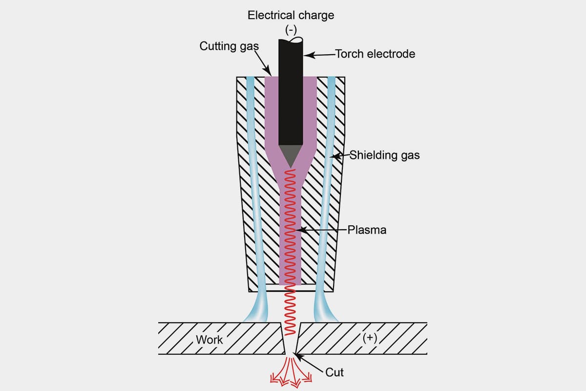
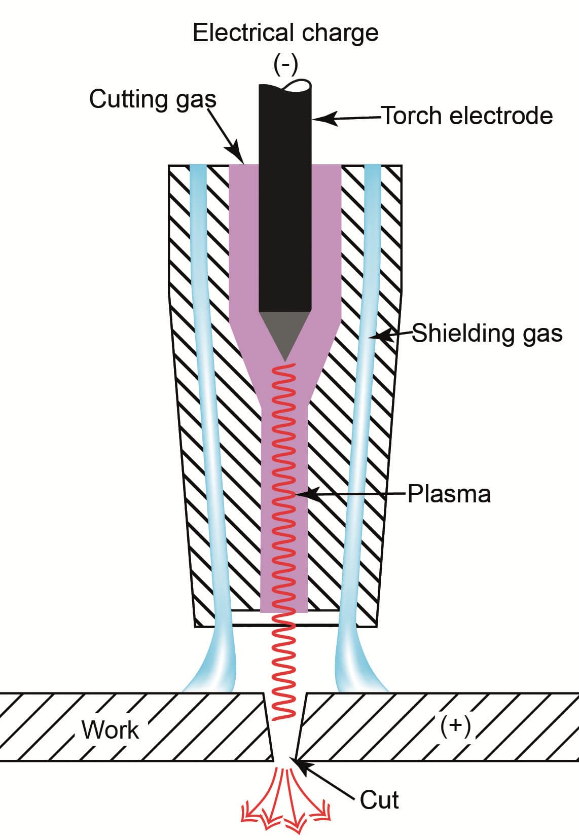
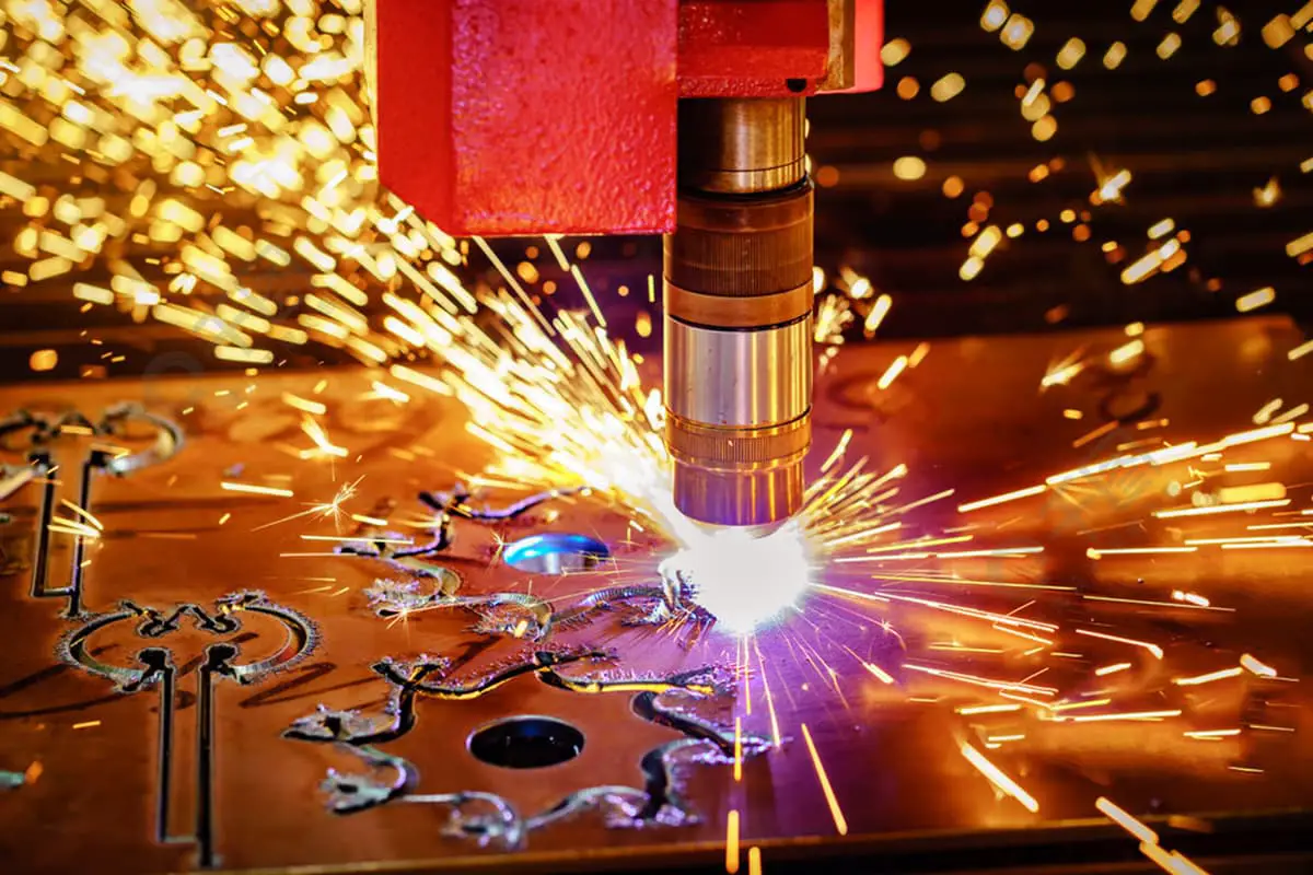
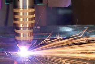
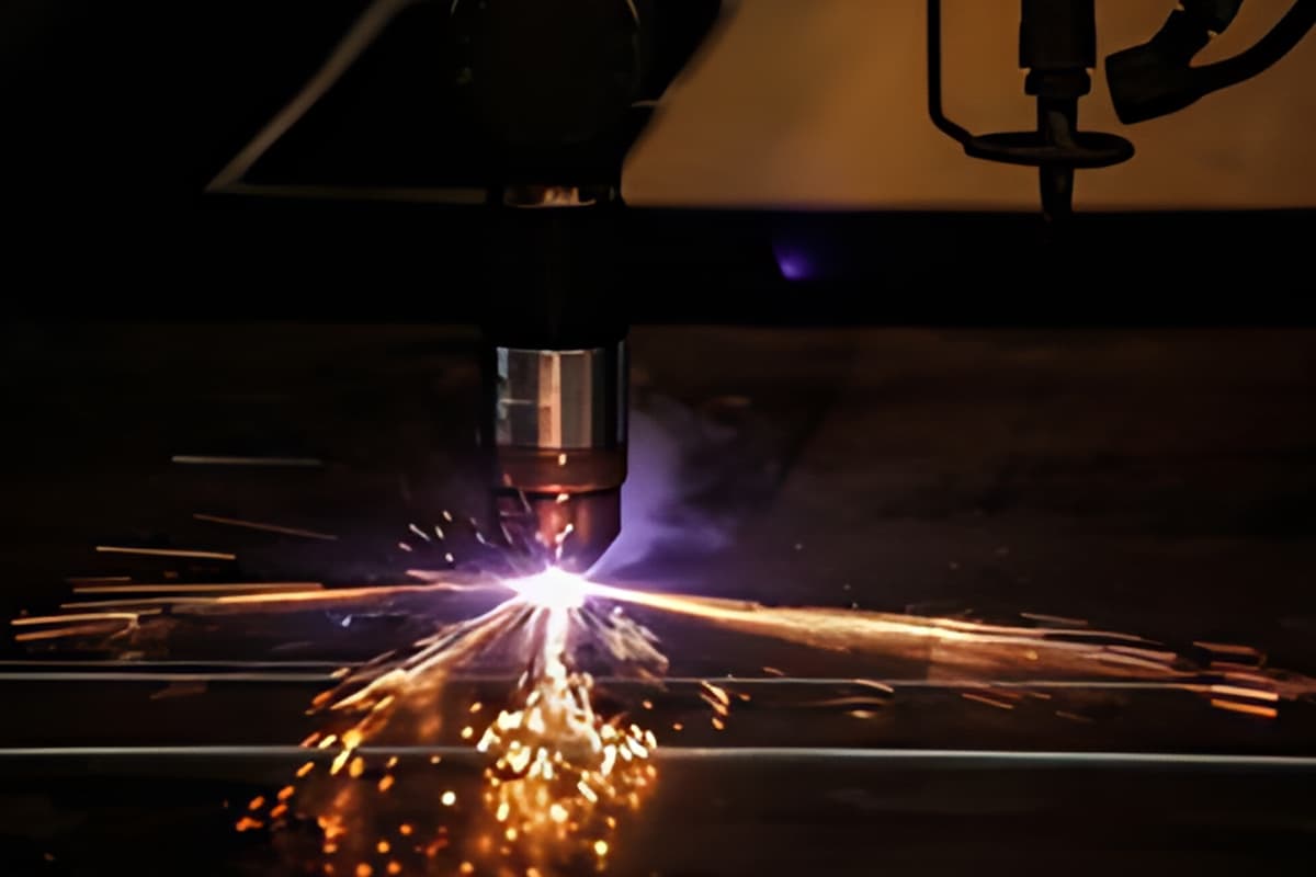
A plasma cutting machine is a novel thermal cutting equipment.
Its working principle involves using compressed air as the working gas and a high-temperature, high-speed plasma arc as the heat source.
This melts the part of the metal being cut, and a high-speed airflow then blows away the melted metal, forming a narrow cutting seam.
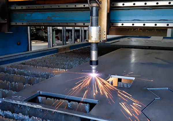
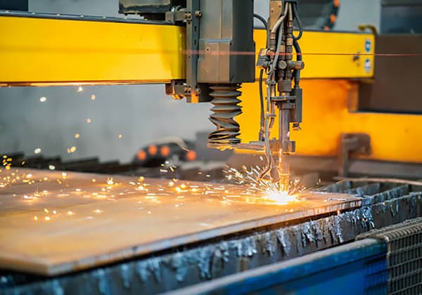
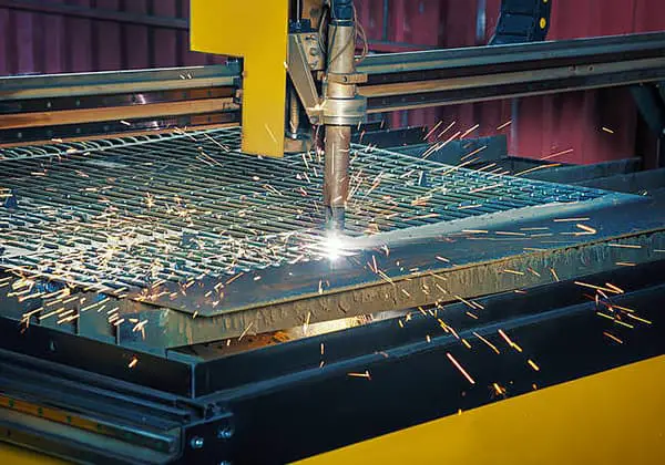
Plasma cutting can be used for cutting various metal materials such as stainless steel, aluminum, copper, cast iron, and carbon steel. It has the advantages of fast cutting speed, narrow cutting seam, smooth cutting edge, small heat-affected zone, minimal workpiece deformation, simple operation, and significant energy-saving effects.
This equipment is suitable for the manufacturing, installation, and maintenance of various mechanical and metal structures, and for cutting, drilling, filling, beveling, and other cutting processes of medium and thin sheets.
Various plasma arc cutting process parameters directly affect the stability, cutting quality, and effect of the cutting process. The main cutting specifications are briefly described as follows:
Figure 4-1: Principle of Plasma Cutting.
(1) Cutting Current
Increasing the cutting current can also enhance the power of the plasma arc, but it is restricted by the maximum allowable current. Otherwise, it can cause the plasma arc column to thicken, increase the cut width, and reduce the electrode life. The model of the cutting torch accessories must correspond to the current setting of the plasma power supply. The current intensity should ideally be within 95% of the working current of the nozzle. For example, the current intensity of a 100A nozzle should be set to no more than 95A.
(2) Gas Flow
Increasing the gas flow can not only raise the arc column voltage but also strengthen the compression on the arc column, making the plasma arc energy more concentrated and the ejection force stronger. This can improve the cutting speed and quality.
However, an excessive gas flow can shorten the arc column, increase heat loss, weaken the cutting ability, and even disrupt the cutting process.
(3) Cutting Nozzle Height
The cutting nozzle height refers to the distance from the end face of the cutting nozzle to the surface of the workpiece being cut. This distance is generally 2-5mm. The appropriate cutting nozzle height is essential to fully exploit the cutting efficiency of the plasma arc.
Otherwise, it can decrease the cutting efficiency and quality, and even cause the cutting nozzle to burn out. The cutting nozzle height can refer to the plasma power supply manual or be determined based on cutting experience.
When piercing, the height of the cutting nozzle should be adjusted to twice the normal cutting height.
(4) Cutting Speed
Various factors directly impact the compression effect of the plasma arc, influencing its temperature and energy density. The high temperature and high energy of the plasma arc determine the cutting speed, linking all these factors to the cutting speed.
To ensure cutting quality, it’s crucial to enhance the cutting speed as much as possible. This not only increases productivity but also reduces the deformation of the parts being cut and the heat-affected zone in the kerf area.
If the cutting speed is inappropriate, it can have the opposite effect, increasing slag and reducing cutting quality.
(5) Cutting Thickness and Process
The thickness of the steel plate greatly influences the choice of cutting process. With the same torch, its piercing ability (thickness) is only half of its cutting ability (thickness).
For the original 100A torch parts from Hypertherm, their recommended cutting ability is 16mm, and piercing ability is 12mm. Therefore, when the thickness of the steel plate is greater than the piercing ability, it is not possible to pierce and cut directly in the middle of the steel plate.
The cutting starting point should be set at the edge of the steel plate to start cutting from the edge.
(6) Pre-treatment of Steel Plate Surface
Steel plates inevitably form an oxide layer on the surface as they pass through a series of intermediate links from the steel plant to the cutting workshop.
Furthermore, an oxide layer also forms and adheres to the surface of the steel plate during the rolling process.
These oxide layers have a high melting point, are not easy to melt, and decrease the cutting speed. At the same time, the splashing of the oxide layer after heating can easily block the cutting nozzle, reducing the service life of the nozzle and electrode.
Therefore, it is necessary to perform rust removal pre-treatment on the steel plate surface before cutting.
The commonly used method is shot blasting rust removal, followed by anti-rust paint spraying.
Small iron sand is sprayed onto the steel plate surface with a shot blasting machine, using the impact force of the iron sand to remove the oxide layer, then flame retardant, conductive anti-rust paint is sprayed on.
Pre-treatment of rust removal and paint spraying before steel plate cutting has become an indispensable part of metal structure production.
Appendix 2: Current Parameter Settings for Arc Voltage Regulator
As the founder of MachineMFG, I have dedicated over a decade of my career to the metalworking industry. My extensive experience has allowed me to become an expert in the fields of sheet metal fabrication, machining, mechanical engineering, and machine tools for metals. I am constantly thinking, reading, and writing about these subjects, constantly striving to stay at the forefront of my field. Let my knowledge and expertise be an asset to your business.
Have you ever wondered how to achieve flawless cuts with CNC plasma machines? Mastering cutting parameters is the key. This article dives into the essential aspects like cutting current, speed,…
Imagine doubling your cutting efficiency while reducing costs—sounds great, right? This article explores optimizing CNC plasma cutting processes for higher accuracy and productivity. From choosing the right starting point to…
Maintaining a CNC plasma cutting machine ensures optimal performance and longevity. In a dusty environment, regular cleaning, lubrication, and inspections are crucial. This article covers daily, weekly, monthly, and quarterly…
Have you ever considered how harmful the smoke and dust from plasma cutting can be? As plasma cutting becomes more prevalent, managing these pollutants is crucial to meeting environmental standards.…
Imagine effortlessly slicing through thick sheets of metal with precision and speed. This article delves into the operational intricacies of a CNC plasma cutting machine, guiding you through everything from…
Have you ever struggled with a plasma cutter that just won't strike an arc? As an experienced mechanical engineer, I'll share insider tips to troubleshoot this frustrating issue. From voltage…
How does a machine cut through tough metal with ease? Plasma cutting machines harness the power of ionized gas at incredibly high temperatures to slice through metals. This article explains…
What if you could slice through metal as effortlessly as a knife through butter? Plasma cutting, with its high-temperature plasma arc, melts and blows away metal, creating precise cuts with…
Have you ever wondered about the cutting-edge technology revolutionizing metal fabrication? Plasma cutting is a game-changer in the industry, offering unparalleled speed, precision, and versatility. In this article, we'll dive…