A Guide to Gas Welding and Cutting Techniques
Have you ever wondered how gas welding works and why it's so crucial in mechanical engineering? This article breaks down the principles, types of gas flames, and materials used in…
What’s the secret behind flawless welds and precise cuts in gas welding and cutting? It all comes down to the flame. This article explores the different types of flames used in gas welding and cutting, detailing their characteristics and applications. Readers will learn how choosing the right flame impacts the quality and efficiency of their welding projects, helping them make informed decisions for their specific needs. Dive in to master the nuances of welding flames and elevate your craftsmanship to the next level.
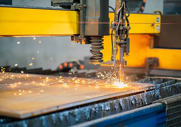
The flame used in gas welding heats, melts, and welds the workpiece while in gas cutting, it serves as a preheating source. It acts as a protective medium for melting metal.
The quality and productivity of gas welding and cutting depend largely on choosing the right flame.
The welding flame must have sufficient temperature, be small in volume with a straight core for concentrated heat.
Additionally, it should be protective enough to prevent oxidation and pollution due to oxygen and nitrogen in the air.
Gas welding and cutting flames come in three types: oxygen-acetylene flames, hydrogen-oxygen flames, and liquefied petroleum gas (LPG) flames.
Oxygen-acetylene flames are mainly used in gas welding and cutting because they have a high temperature (approximately 3200℃) and good heating concentration.
Hydrogen-oxygen flames, the earliest gas welding flame utilized, have a low combustion temperature (up to 2770℃) and pose a risk of explosion; thus, they are primarily used for lead welding and underwater flame cutting.
LPG flames burn propane (C3H8) and other gases such as butane (C4H10) and butene (C4H8). They are mainly used for metal cutting and can reduce over-burning at the edge of the cut.
The flame produced by burning LPG is increasingly being used for steel cutting and welding nonferrous metals.
The process of acetylene (C2H2) combustion in oxygen (O2) occurs in two stages. Firstly, acetylene is decomposed into carbon (C) and hydrogen (H2) due to heating.
Subsequently, carbon reacts with oxygen in the mixture, producing carbon monoxide (CO), which marks the first stage of combustion. Secondly, the second stage depends on the oxygen in the air.
In this stage, CO and H2 react with oxygen to form carbon dioxide (CO2) and water (H2O), respectively. This reaction releases heat, making the entire process an exothermic one.
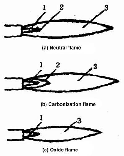
The oxygen-acetylene flame can be classified into three types: neutral flame, carburizing flame, and oxidizing flame, depending on the mixing ratio of oxygen and acetylene. Their structures and shapes are shown in Figure 2-2.
The neutral flame, formed by burning a mixture of oxygen and acetylene at a volume ratio (O2/C2H2) of 1.1~1.2, does not have excess oxygen or free carbon in the first combustion stage.
A neutral flame can also be obtained when the ratio of oxygen to propane (C3H8) volume is 3.5. The neutral flame comprises three distinct areas: the core, inner flame, and outer flame, as shown in Figure 2-2(a).
1. Core
The core of the neutral flame is conical in shape, bright white, and has clear contours. The core is composed of oxygen and acetylene and is surrounded by a layer of carbon particles generated by acetylene decomposition.
Due to the hot carbon particles emitting bright white light, the contour of the core appears bright and clear.
The first stage of combustion takes place inside the core. Although the core is bright, its temperature is low (800~1200℃) because acetylene decomposition absorbs some heat.
2. Inner Flame
The inner flame consists mainly of the incomplete combustion products of acetylene, namely carbon and hydrogen gas from the core, and the combustion products of carbon monoxide and hydrogen gas produced from the reaction with oxygen.
The inner flame is located outside the layer of carbon particles and appears blue-white with dark blue lines. The inner flame is in the front 2-4mm part of the core and burns intensely at the highest temperature of 3100~3150℃.
During gas welding, this temperature range is usually used for welding, hence called the weld zone.
Since the gases in the inner flame, carbon monoxide (CO), and hydrogen gas (H2) play a reducing role, welding of carbon steel is generally carried out in the inner flame.
The welding area of the workpiece is placed 2-4mm away from the tip of the core.
The content of CO in the gases in the inner flame is 60% ~ 66%, and H2 accounts for 30% ~ 34%. Since it plays a reducing role in many metal oxides, the weld zone is also known as the reducing zone.
3. Outer Flame
The outer flame is outside the inner flame, and the color of the outer flame changes from light purple to orange-yellow from the inside outward.
In the outer flame, carbon monoxide and hydrogen gas generated in the inner flame reaction fully combust with oxygen from the air, which is the second stage of combustion.
The products of combustion in the outer flame are carbon dioxide and water.
The temperature of the outer flame is 1200~2500℃. Since carbon dioxide (CO2) and water (H2O) can easily decompose at high temperatures, the outer flame has an oxidizing nature.
Neutral flame is widely used for welding carbon steel, brass, and low-alloy steel.
The temperature of the neutral flame varies along the axis of the flame, as shown in Figure 2-3.
The highest temperature of the neutral flame is within the range of the inner flame, which is 2~4mm away from the end of the core, where the temperature can reach 3150℃. The farther away from this position, the lower the temperature of the flame.
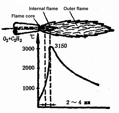
In addition, the temperature of the flame on the cross-section is different. The center of the section has the highest temperature, and the temperature decreases towards the edge.
Since the core and outer flame of the neutral flame have lower temperatures and the inner flame has a reducing nature, it not only has the highest temperature but can also improve the properties of the welded metal.
Therefore, when welding and cutting most metals and their alloys with a neutral flame, the inner flame is utilized.
The carburizing flame is a gas flame formed by burning a mixture of oxygen and acetylene with a volume ratio (O2/C2H2) of less than 1.1, where incomplete combustion occurs due to excess acetylene.
The carburizing flame contains free carbon, which has strong reducing and certain carburizing effects.
The carburizing flame can be divided into three parts: the core, inner flame, and outer flame, as shown in Figure 2-2(b).
The entire flame of the carburizing flame is longer and softer than that of the neutral flame, and as the supply of acetylene increases, the carburizing flame becomes longer and softer, and its straightness deteriorates.
When there is a large amount of excess acetylene, black smoke appears due to the lack of oxygen required for complete combustion of acetylene.
The core of the carburizing flame is longer, blue-white in color and composed of carbon monoxide (CO), hydrogen (H2), and carbon particles.
The outer flame of the carburizing flame is particularly long, orange-red in color and consists of water vapor, carbon dioxide, oxygen, hydrogen, and carbon particles.
The temperature of the carburizing flame is 2700~3000℃. Since there is excess acetylene in the carburizing flame, it can decompose into hydrogen and carbon.
When welding carbon steel, free carbon in the flame will infiltrate the weld pool, increasing the carbon content of the weld and making the weld metal stronger but less ductile.
Moreover, excessive hydrogen can enter the molten pool, causing porosity and cracking in the weld.
Therefore, the carburizing flame cannot be used to weld low-carbon steel and low-alloy steel.
However, a slight carburizing flame is widely used and can be used for welding high-carbon steel, medium-alloy steel, high-alloy steel, cast iron, aluminum, and aluminum alloys.
The oxidizing flame is a gas flame formed by burning a mixture of oxygen and acetylene with a volume ratio (O2/C2H2) greater than 1.2, where there is excess oxygen forming an oxidizing rich oxygen zone outside the pointed flame core, as shown in Figure 2-2(c).
Due to the high oxygen content in the oxidizing flame, the oxidation reaction is intense, causing the core, inner and outer flames to shorten, and the inner flame is almost invisible.
The core of the oxidizing flame is light purple-blue in color with an unclear contour, while the outer flame is blue in color, straight and emits a sharp “hissing” sound when burning.
The length of the oxidizing flame depends on the pressure of oxygen and the proportion of oxygen in the flame.
The higher the proportion of oxygen, the shorter the entire flame and the louder the noise.
The temperature of the oxidizing flame can reach 3100~3400℃. Due to the abundant supply of oxygen, the entire flame has an oxidizing nature.
If the oxidizing flame is used to weld general carbon steel, it will cause oxidation of the molten metal and burning of alloy elements, increasing the amount of oxide and porosity in the weld metal and enhancing the boiling phenomenon of the weld pool, greatly reducing the quality of the weld.
Therefore, the oxidizing flame should not be used for welding general materials.
However, when welding brass and tin bronze, a slight oxidizing flame can be used to generate an oxide film with covering on the surface of the weld pool, preventing the evaporation of zinc and tin.
Since the temperature of the oxidizing flame is very high, it is often used to improve efficiency during flame heating. When gas cutting, the oxidizing flame is usually used.
The neutral flame, carburizing flame, and oxidizing flame described above are suitable for welding different materials due to their different properties.
The ratio of oxygen to acetylene (O2/C2H2) has a significant impact on the quality of welding.
The choice of flame type for various metal materials during gas welding is detailed in Table 2-1.
Table 2-1 Selection of Oxyacetylene Flame for Various Metal Materials.
| Welding material | Apply flame | Welding material | Apply flame |
| Mild steel | Neutral flame or slightly carbonized flame | Chromium nickel stainless steel | Neutral flame or slightly carbonized flame |
| Medium carbon steel | Neutral flame or slightly carbonized flame | Purple copper | Neutral flame |
| Low alloy steel | Neutral flame | Tin bronze | Mild oxidation flame |
| High carbon steel | Mild carbonization flame | Brass | Oxide flame |
| Grey cast iron | Carbonation flame or mild carbonization flame | Aluminum and its alloys | Neutral flame or slightly carbonized flame |
| High speed steel | Carbonization flame | Lead, tin | Neutral flame or slightly carbonized flame |
| Manganese steel | Mild oxidation flame | Monel alloy | Carbonization flame |
| Galvanized iron sheet | Mild carbonization flame | Nickel | Carbonation flame or mild carbonization flame |
| Chromium stainless steel | Neutral flame or slightly carbonized flame | Hard alloy | Carbonization flame |
The process parameters for gas welding include the type and diameter of welding wire, flux, flame type, flame efficiency, type of welding torch and nozzle, nozzle inclination angle, and welding speed.
Due to differences in the material of the weldment, working conditions of gas welding, size and shape of the workpiece and welding position, operator’s habits, and gas welding equipment, the selected gas welding process parameters may vary.
The following is an explanation on the general gas welding process parameters (i.e., welding specifications) and their impact on welding quality:
(1). Selection of Welding Wire Diameter
The diameter of the welding wire should be determined based on factors such as the thickness of the weldment, the type of groove, the position of the weld seam, and the flame efficiency.
When the flame efficiency is constant, that is, when the melting speed of the welding wire is determined, if the welding wire is too fine, it often melts and drops before the weldment has melted during welding, which can easily cause poor fusion, uneven welding waves, and uneven weld width.
If the welding wire is too thick, the time required to melt the welding wire will be prolonged, and the heating range of the welding piece will increase, causing the welding heat-affected zone to be enlarged and making it easy to produce overheating of the structure, thus reducing the quality of the welded joint.
The diameter of the welding wire is usually initially selected based on the thickness of the weldment and then adjusted and determined after trial welding.
For carbon steel gas welding, the selection of welding wire diameter can refer to Table 2-2.
Table 2-2 Relationship Between Weld Thickness and Welding Wire Diameter (mm)
| Workpiece thickness | 1.0~2.0 | 2.0~3.0 | 3.0~5.0 | 5.0~10.0 | 10~15 |
| Welding wire | 1.0~2.0 or without welding wire | 2.0~3.0 | 3.0~4.0 | 3.0~5.0 | 4.0~6.0 |
When multi-layer welding, thinner welding wires should be used for the first and second layers, and thicker welding wires can be used for subsequent layers.
In general, a thicker welding wire should be selected for flat welding than for other welding positions, and for right welding method, a slightly thicker welding wire should be chosen than for left welding method.
(2) Selection of Flame Properties
Generally speaking, a neutral flame should be used when it is necessary to minimize element burning loss; a carburizing flame should be used when it is necessary to increase carbon content and create a reducing atmosphere; an oxidizing flame should be used when the base material contains low boiling point elements (such as tin (Sn) and zinc (Zn)), which require an oxide film covering the surface of the melt pool to prevent the evaporation of low-melting-point elements.
In short, the selection of the flame properties should be based on the type and performance of the welding materials.
Since the gas welding quality and the strength of the weld metal are greatly related to the flame type, the flame composition should be continuously adjusted throughout the entire welding process to maintain the flame properties in order to achieve a high-quality welded joint.
The properties of the welding flames used for gas welding of different metal materials are referred to Table 2-1.
(3) Selection of Flame Efficiency
The flame efficiency refers to the consumption of combustible gas (acetylene) per unit time, with units of L/h. The physical meaning of flame efficiency is the energy provided by the combustible gas in a unit time.
The size of the flame efficiency is determined by the type of welding torch and the size of the nozzle. The larger the nozzle size, the higher the flame efficiency.
Therefore, the selection of flame efficiency actually determines the type of welding torch and nozzle size. The size of the flame efficiency mainly depends on the pressure and flow rate (consumption) of oxygen and acetylene in the mixed gas.
The coarse adjustment of the flow rate is achieved by replacing the welding torch and nozzle, while the fine adjustment of the flow rate is achieved by adjusting the oxygen and acetylene regulators on the welding torch.
The flame efficiency should be selected based on the thickness of the weldment, the melting point and thermal conductivity of the base material, and the spatial position of the weld seam.
For thicker weldments, metals with higher melting points, copper, aluminum, and their alloys with better thermal conductivity, larger flame efficiencies should be used to ensure that the weldment is fully penetrated.
Conversely, when welding thin plates, the flame efficiency should be appropriately reduced to prevent burn-through. A slightly larger flame efficiency can be used for flat welds than for other positions.
In actual production, as long as the welding quality can be ensured, a larger flame efficiency should be selected as much as possible.
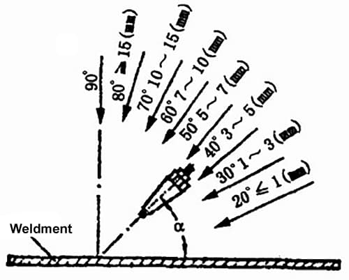
(4) Selection of Nozzle Inclination Angle
The nozzle inclination angle refers to the angle between the centerline of the nozzle and the plane of the workpiece. See Figure 2-4 for details.
The size of the nozzle inclination angle is mainly determined by factors such as the size of the nozzle, the thickness of the workpiece, the melting point and thermal conductivity of the base material, and the spatial position of the weld seam.
When the nozzle inclination angle is large, the heat loss is small, the workpiece receives more heat, and the temperature rises faster; conversely, when the heat loss is large, the workpiece receives less heat, and the temperature rises slower.
In general, for low-carbon steel gas welding, the relationship between the nozzle inclination angle and the thickness of the workpiece can refer to Figure 2-4.
Generally speaking, for thicker workpieces, metals with higher melting points or better thermal conductivity, a larger nozzle inclination angle should be chosen.
Conversely, for thinner workpieces, a smaller nozzle inclination angle can be selected.
During gas welding, the tilt angle of the welding nozzle should also vary according to the welding situation.
For example, at the beginning of the welding process, in order to quickly form a molten pool, a tilt angle of 80° to 90° should be used; when the welding is finished, in order to better fill the arc pit and avoid burn through or overheating at the end of the weld seam, the welding nozzle should be raised appropriately, the tilt angle gradually reduced, and the welding nozzle heated alternately towards the welding wire or molten pool.
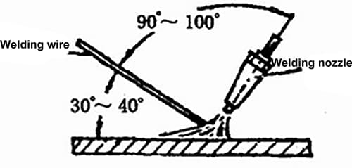
During gas welding, the angle between the welding wire and the surface of the weldment is generally 30° to 40°, and the angle with the centerline of the welding nozzle is 90° to 100°, as shown in Figure 2-5.
5. Selection of Welding Speed
The welding speed should be as high as possible while ensuring the welding quality, based on the proficiency level of the welder in order to reduce the heating time of the weldment and increase productivity.
Generally speaking, for thick and high melting point weldments, a slower welding speed is required to avoid incomplete fusion defects, while for thin and low melting point weldments, a faster welding speed is required to avoid burn-through and overheating that can reduce welding quality.
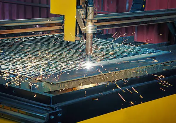
The main gas cutting process parameters include the type of cutting torch and cutting oxygen pressure, cutting speed, preheating flame energy rate, tilt angle between the cutting nozzle and the workpiece, and distance between the cutting nozzle and the workpiece surface.
(1) Type of Cutting Torch and Cutting Oxygen Pressure
For thicker materials, the type of cutting torch, size of cutting nozzle, and oxygen pressure should all increase, according to Table 2-10. When the material being cut is thinner, the cutting oxygen pressure can be appropriately reduced.
However, the cutting oxygen pressure cannot be too low or too high. If the cutting oxygen pressure is too high, the cutting groove will be wider, the cutting speed will decrease, and the roughness of the cutting surface will increase.
It will also have a strong cooling effect on the workpiece. If the oxygen pressure is too low, the oxidation reaction during the gas cutting process will slow down, and the cutting oxide slag cannot be blown away, leaving difficult-to-remove slag bonds on the back of the cutting seam, and even preventing the workpiece from being cut through.
In addition to the above impact on gas cutting quality, the purity of oxygen also has a great influence on oxygen consumption, cutting quality, and cutting speed.
If the oxygen purity decreases, the metal oxidation process will slow down, the cutting speed will decrease, and the oxygen consumption will increase.
Figure 2-6 shows the curve of the effect of oxygen purity on gas cutting time and oxygen consumption.
In the range of oxygen purity from 97.5% to 99.5%, for every 1% decrease in oxygen purity, the gas cutting time for a 1m long cut will increase by 10% to 15%, and the oxygen consumption will increase by 25% to 35%.
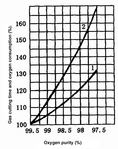
Impurities in oxygen such as nitrogen will absorb heat during gas cutting, forming a gas film on the cutting surface that hinders metal combustion, causing a decrease in gas cutting speed and an increase in oxygen consumption, resulting in a rough cutting surface.
Therefore, the purity of oxygen used for gas cutting should be as high as possible, generally requiring a purity of 99.5% or higher.
If the purity of oxygen drops below 95%, the gas cutting process will be difficult to perform.
(2) Cutting Speed
The cutting speed is generally related to the thickness of the workpiece and the type of cutting nozzle, with slower speeds required for thicker materials and faster speeds for thinner ones.
The cutting speed is controlled by the operator based on the amount of back drag on the cutting groove.
Back drag refers to the distance in the horizontal direction between the starting point and ending point of the cutting oxygen flow trajectory on the cutting surface during oxygen cutting, as shown in Figure 2-7.
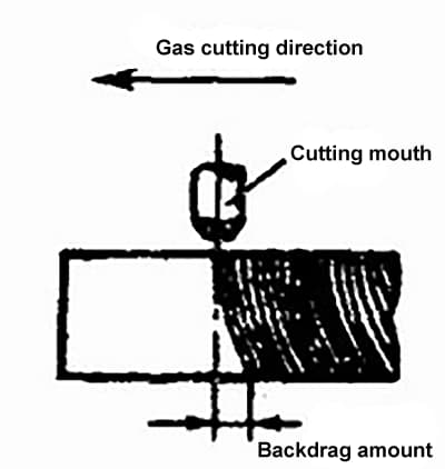
Back drag is unavoidable during gas cutting, especially when cutting thick plates. The appropriate gas cutting speed should be chosen to minimize the back drag produced by the cutting groove.
If the cutting speed is too slow, it will cause uneven edges and even local melting, making slag removal more difficult after cutting. If the cutting speed is too fast, it will result in excessive back drag, resulting in an unclean cut and even an inability to cut through.
In summary, an appropriate gas cutting speed can ensure cutting quality while reducing oxygen consumption.
(3) Preheating flame energy rate
The preheating flame is used to heat the metal workpiece to the temperature at which the metal can burn in oxygen, and maintain this temperature, while also causing the oxide layer on the surface of the steel to peel off and melt, facilitating contact between the cutting oxygen flow and the metal.
During gas cutting, a neutral flame or slightly oxidizing flame should be used for preheating. A carburizing flame cannot be used because the presence of free carbon in the flame will increase the carbon content of the cutting edge.
During the cutting process, attention must be paid to adjust the preheating flame at any time to prevent changes in its properties.
The size of the preheating flame energy rate is related to the thickness of the workpiece, with a greater rate required for thicker materials, but it should be prevented from being too high or too low during gas cutting.
For example, when cutting thick steel plates, due to the slower cutting speed, the preheating flame energy rate should be lowered to prevent the upper edge of the cutting groove from melting.
If the energy rate is too high at this time, continuous bead-like steel particles may be produced on the upper edge of the cutting groove, or even rounded corners may melt, resulting in an increase in adherent slag on the back of the cutting groove and affecting gas cutting quality.
When cutting thin steel plates, due to the faster cutting speed, the preheating flame energy rate can be increased accordingly, but the cutting nozzle should be kept at a greater distance from the workpiece and at a certain tilt angle.
If the energy rate is too low at this time, the workpiece will not receive enough heat, resulting in a slower gas cutting speed or even an interruption of the gas cutting process.
(4) Tilt angle between cutting nozzle and workpiece
The size of the tilt angle of the cutting nozzle is mainly determined by the thickness of the workpiece.
Generally,
Details of the tilt angle between the cutting nozzle and the workpiece are shown in Figure 2-8.
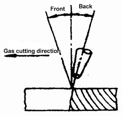
The tilt angle between the cutting nozzle and the workpiece has a direct impact on gas cutting speed and back drag. If the tilt angle is not chosen appropriately, it will not only fail to improve the gas cutting speed, but also increase oxygen consumption and even cause difficulties in gas cutting.
(5) Distance between cutting nozzle and workpiece surface
Generally, the distance between the flame core and the workpiece surface should be kept within the range of 3-5mm, which provides optimal heating conditions and minimizes the possibility of carburization.
If the flame core touches the workpiece surface, it will not only cause melting at the upper edge of the cutting groove, but also increase the possibility of carburizing the cutting groove.
In general,

As the founder of MachineMFG, I have dedicated over a decade of my career to the metalworking industry. My extensive experience has allowed me to become an expert in the fields of sheet metal fabrication, machining, mechanical engineering, and machine tools for metals. I am constantly thinking, reading, and writing about these subjects, constantly striving to stay at the forefront of my field. Let my knowledge and expertise be an asset to your business.