How can manufacturers tackle the challenges of drilling deep holes with precision and efficiency? This article dives into the world of deep hole drilling tools, exploring various types and their specific applications. You’ll learn about the latest advancements in drill bit technology, their characteristics, and how to overcome common obstacles in deep hole machining. Get ready to enhance your knowledge and boost your manufacturing processes with these crucial insights.
Deep hole machining is a challenging aspect of mechanical engineering and a current hot topic in processing. As the demands for complex deep hole machining increase, requiring both high precision and efficiency, mastering the performance and application range of various deep hole drills becomes crucial.
This article mainly introduces the characteristics, application range, and considerations of various deep hole drill bits.
What is a Deep Hole?
In mechanical manufacturing, a cylindrical hole with a depth exceeding ten times its diameter is generally called a deep hole.
Deep holes are categorized based on the ratio of hole depth (L) to diameter (D), usually divided into general deep holes, medium deep holes, and special deep holes. (Note: The larger the L/D ratio, the more challenging the machining process.)
Classification of Deep Holes by L/D Ratio
L/D = 10–20, categorized as general deep holes. Typically machined with long twist drills on drilling or turning machines.
L/D = 20–30, considered medium deep holes. Commonly machined on turning machines.
L/D = 30–100, classified as special deep holes. They require deep hole drills on dedicated deep hole drilling machines or special equipment.
Characteristics of Deep Hole Machining:
The rigidity and strength of the tool bar are limited by the diameter of the hole, resulting in poor rigidity and low strength. This can lead to vibration, rippling, and tapering during cutting, affecting the straightness and surface roughness of the deep hole.
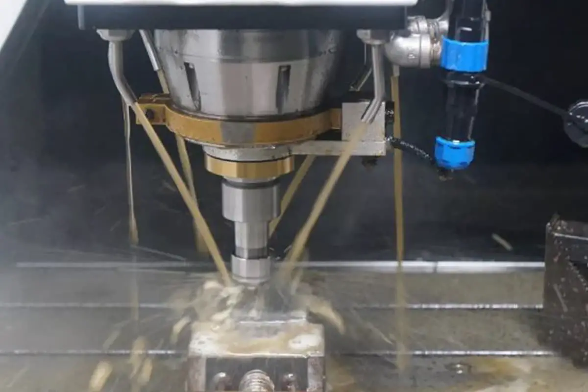
During drilling and reaming, it is difficult to deliver coolant and lubricant to the cutting area without special devices, reducing tool life and complicating chip removal.
In deep hole machining, direct observation of the cutting process is not possible. Operators must rely on experience, listening to cutting sounds, observing chips, feeling for vibrations, monitoring workpiece temperature, and watching instruments (oil pressure and ammeters) to ensure normal cutting.
Chip removal is challenging and requires reliable methods to break and control the length and shape of chips for smooth ejection and to prevent blockages.
To ensure smooth machining and achieve the required quality, it’s important to add internal (or external) chip removal devices, tool guides and supports, and high-pressure cooling and lubrication systems.
Poor heat dissipation in tools leads to increased cutting temperatures, reducing tool life.
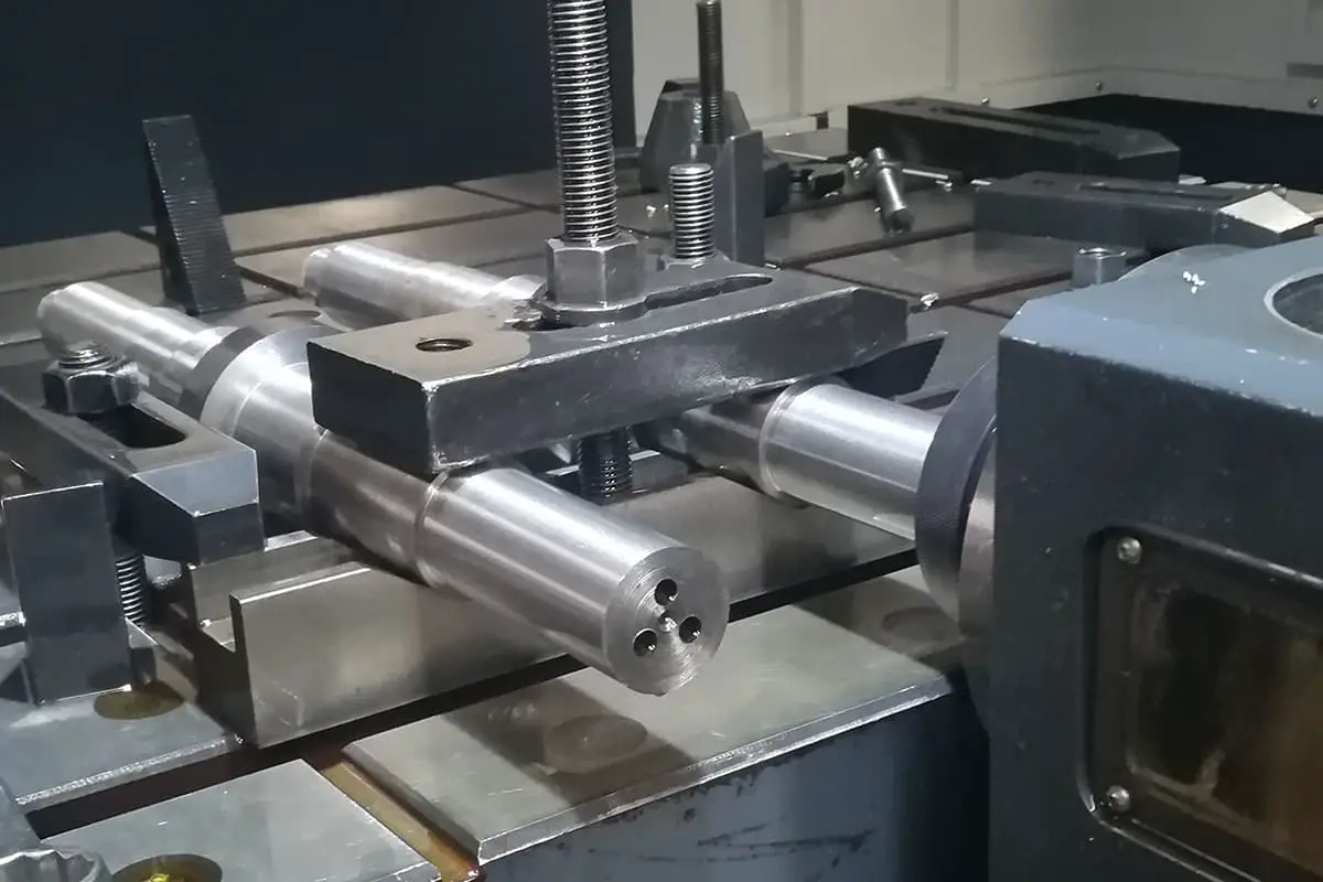
Types and Structures of Deep Hole Drill Bits
Deep hole drills are categorized into external and internal chip removal types. External chip removal includes gun drills and integral carbide deep hole drills (which can be with or without cooling holes); internal chip removal includes BTA deep hole drills, ejector drills, and DF system deep hole drills. The types and application ranges of deep hole drills are as follows.
type
Scope of use
External chip removal deep hole drill (gun drill)
Used for processing Φ 2- Φ Deep holes with a length to diameter ratio of 20mm, L/D>100, accuracy of H8-H10, and surface roughness value of Ra=12.5-3.2um have lower production efficiency than internal chip removal deep hole drills
BTA internal chip removal deep hole drill
Used for processing Φ 6- Φ A deep hole with a length to diameter ratio of 60mm, L/D>100, accuracy of H7-H9, and surface roughness value of Ra=3.2um, with a production efficiency more than three times that of external chip removal
Spray suction drill
Used for processing Φ 16- Φ In the case of 60mm and low cutting fluid pressure, other performance is the same as that of internal chip removal deep hole drilling
DF system deep hole drill
A drill pipe is supported by cutting fluid, reducing vibration, providing a larger chip removal space, high machining efficiency, and good accuracy. It can be used for high-precision deep hole machining; The production efficiency is 3-6 times higher than that of gun drills and 3 times higher than that of BTA internal chip drills
Characteristics and Application Range of Various Deep Hole Drill Bits
1. Gun Drills
Named for their initial use in the military industry for machining gun barrels and cannons, gun drills are effective for a wide range of deep hole machining, from mold steel, fiberglass, Teflon, and other plastics to high-strength alloys (like P20 and chrome-nickel iron alloys). In deep hole machining with strict tolerance and surface roughness requirements, gun drills ensure dimensional accuracy, positional accuracy, and straightness.
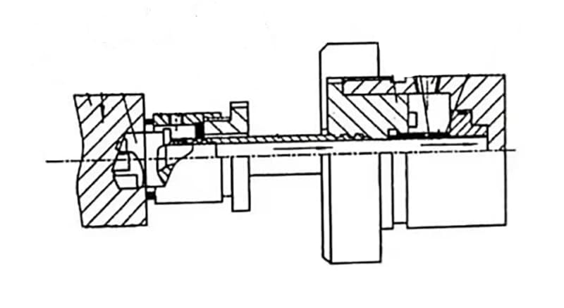
Working principle of the gun drill system: Cutting fluid enters the drill rod through the oil inlet at the tailstock, cools and lubricates the drill head, and ejects chips through the external V-shaped groove. This system is primarily used for small diameter deep holes (less than 20mm).
Gun drill applications: Gun drills (external chip removal deep hole drills) are mainly used for machining holes with diameters of φ2–20mm, aspect ratios L/D >100, precision IT8–IT10, and surface roughness values Ra=12.5–3.2μm. They are less efficient than internal chip removal deep hole drills.
2. BTA Internal Chip Removal Deep Hole Drill
To accommodate more complex large diameter deep hole machining requirements, the BTA internal chip removal deep hole drilling technology was developed. As chips are ejected internally, avoiding contact with the machined surface, BTA offers higher surface quality and a wider range of hole diameters compared to gun drilling.
In the BTA system, both the drill head and rod are hollow cylinders. The working principle is illustrated below: Pressurized cutting fluid enters the oiler, flows through the annular space formed between the drill rod and hole wall to the cutting area for cooling and lubrication, and pushes chips into the chip exit on the drill head, which are then ejected through the inner cavity of the rod.
Internal chip removal deep hole drills are suitable for machining diameters above 20mm, aspect ratios up to 100, precision IT7–IT10, and surface roughness Ra3.2–1.6μm. Their production efficiency is more than three times that of external chip removal.
Main drawbacks of BTA internal chip removal deep hole drills: Special machine tools are required, along with a cutting fluid chip separation device using gravity sedimentation or electromagnetic separation for recycling the cutting fluid. Additionally, a high-pressure zone forms between the workpiece and oiler during cutting, necessitating a reliable seal before drilling.
3. Ejector Drill
The internal chip removal deep hole drilling system suffers from significant loss in the annular fluid channel, requiring higher pressure and flow rates during machining. To address this, the market has developed a more efficient and higher quality drilling technology – the ejector drill.
The ejector drill employs the principle of fluid dynamics’ ejector effect, using a dual-tube internal chip removal method invented with concentric drill rods. The tool is connected to the machine through a connector, and the ejector drill system uses a double-layered tubular drill rod. 2/3 of the pressurized cutting fluid enters the annular space between the inner and outer drill rods, flowing towards the cutting area for cooling and lubrication, and pushing the chips into the inner cavity of the drill rod.
The remaining 1/3 of the cutting fluid is injected at high speed from crescent-shaped nozzles on the inner drill rod, creating a low-pressure area within the inner cavity, which sucks in the cutting fluid carrying chips. Under the dual action of injection and suction, chips are rapidly ejected from the outlet.
The oil supply in ejector drilling is through a rotating connector, and the guide seat primarily serves a supporting role, allowing it to be detached from the workpiece. This is highly advantageous for five-axis machining, often involving non-planar surfaces where the guide seat cannot be in direct contact with the workpiece. Additionally, the vacuum effect created during ejector drilling facilitates chip removal, offering greater flexibility in use.
Ejector drills are mainly suitable for machining holes with aspect ratios not exceeding 100 and diameters ranging from 18 to 65mm, with precision levels between IT9 and IT11.
4. DF System Deep Hole Drill
The DF system deep hole drill, also known as a single-tube ejector drill, is abbreviated from “Double Feeder”. This tool, developed in the mid-1970s by Nippon Metal Company Ltd., Japan, evolved from the standard ejector drill. It combines the chip ejection method of the standard BTA internal chip removal deep hole drill with the chip suction method of the ejector drill.
Its single drill rod is supported by cutting fluid, reducing vibration and allowing larger chip removal space, resulting in higher efficiency and precision. It is suitable for high-precision deep hole machining; its production efficiency is 3 to 6 times that of gun drills and three times higher than BTA internal chip removal drills, but at a higher cost.
The above drill head configurations indicate that regardless of the chip removal method, the system comprises the workpiece, tools, special accessories, machine tools, and control systems.
The special accessories depend on the cutting fluid supply method, chip removal method, and the relative motion between the workpiece and the tool. Hence, deep hole machining requires specialized equipment and accessories, making the equipment structure complex and costly.
Precautions for Deep Hole Machining
Operational Key Points for Deep Hole Machining
Ensure the concentricity of the spindle and tool guide bushing, tool bar support bushing, and workpiece support bushing; maintain a clear and normal cutting fluid system; avoid center holes on the machined end face and drilling on inclined surfaces; keep chip shapes normal, avoiding straight band-shaped chips; use higher speeds for through-hole machining, reducing speed or stopping the machine as the drill is about to break through to prevent damage to the drill.
Considerations for Cutting Fluid in Deep Hole Machining
Deep hole machining generates significant cutting heat, which is difficult to dissipate, requiring sufficient cutting fluid for tool lubrication and cooling.
Typically, a 1:100 emulsion or extreme pressure emulsion is used; for higher precision and surface quality requirements or when machining tough materials, choose extreme pressure emulsion or high-concentration extreme pressure emulsion. The cutting oil’s kinematic viscosity is usually chosen at (40°C) 10–20cm²/s, with a fluid flow rate of 15–18m/s; use lower viscosity cutting oils for smaller diameters; for high-precision deep hole machining, a cutting oil mixture of 40% extreme pressure sulfurized oil + 40% kerosene + 20% chlorinated paraffin can be used.
The pressure and flow rate of the cutting fluid are closely related to the hole diameter and machining method, as detailed in the reference table.
External chip removal deep hole drill
Internal chip removal deep hole drill
Aperture /mm
Pressure /MPa
Flow rate /(L/min)
Aperture /mm
Pressure /MPa
Flow rate /(L/min)
4-10
2.5-6
8-20
8-15
5-6.5
20-50
10-15
2-5
20-30
15-25
4-5.5
50-70
15-20
1.5~4.5
30-40
25-35
3-4. 5
70-100
20-25
1.5-4
40-50
35-45
2.5-3.5
100-125
25-30
1.5-3
50-60
45-80
2-3
125-200
Precautions for Using Deep Hole Drills
Ensure the end face of the workpiece is perpendicular to the axis to guarantee a reliable seal.
Pre-drill a shallow hole at the workpiece hole position before official machining to guide and center the drill.
Use automatic feed to ensure tool life.
Replace any worn components in the fluid injector and movable center support to avoid affecting drilling accuracy.
Conclusion
Deep hole machining holds a vital position in the field of mechanical machining, accounting for about 40% of hole machining. The continuous emergence of new high-hardness and high-value difficult-to-machine deep hole workpieces
demands higher processing depths, precision, and efficiency. As a key process and challenging aspect, only by understanding the concept of deep holes, the characteristics and challenges of deep hole machining, and comprehensively knowing the types, structures, and application ranges of various deep hole drill bits, can the efficiency of deep hole machining be improved.
As the founder of MachineMFG, I have dedicated over a decade of my career to the metalworking industry. My extensive experience has allowed me to become an expert in the fields of sheet metal fabrication, machining, mechanical engineering, and machine tools for metals. I am constantly thinking, reading, and writing about these subjects, constantly striving to stay at the forefront of my field. Let my knowledge and expertise be an asset to your business.
Have you ever wondered why machining holes is more challenging than shaping external surfaces? This article reveals the complexities of drilling, reaming, boring, and trepanning. Learn how different tools and…
Ever wondered which companies are shaping the future of lathe manufacturing in China? In this article, we explore the top players in the industry, highlighting their innovations and contributions. You'll…
Have you ever thought about how intricate parts are made with precision? This article explores four fascinating methods: Electrical Discharge Machining (EDM), Electrochemical Machining (ECM), Ultrasonic Machining (USM), and Laser…
Discover the secret language that brings machines to life! In this captivating blog post, we'll dive into the fascinating world of G-code and M-code, the essential programming commands that power…
Ever wondered how tiny holes in metal parts are made so precisely? This article explores the fascinating world of hole machining, covering drilling, reaming, countersinking, and boring. Learn how each…
Have you ever wondered how we can precisely cut through tough materials like glass and ceramics? In this article, we explore ultrasonic machining, a fascinating technology that uses high-frequency vibrations…
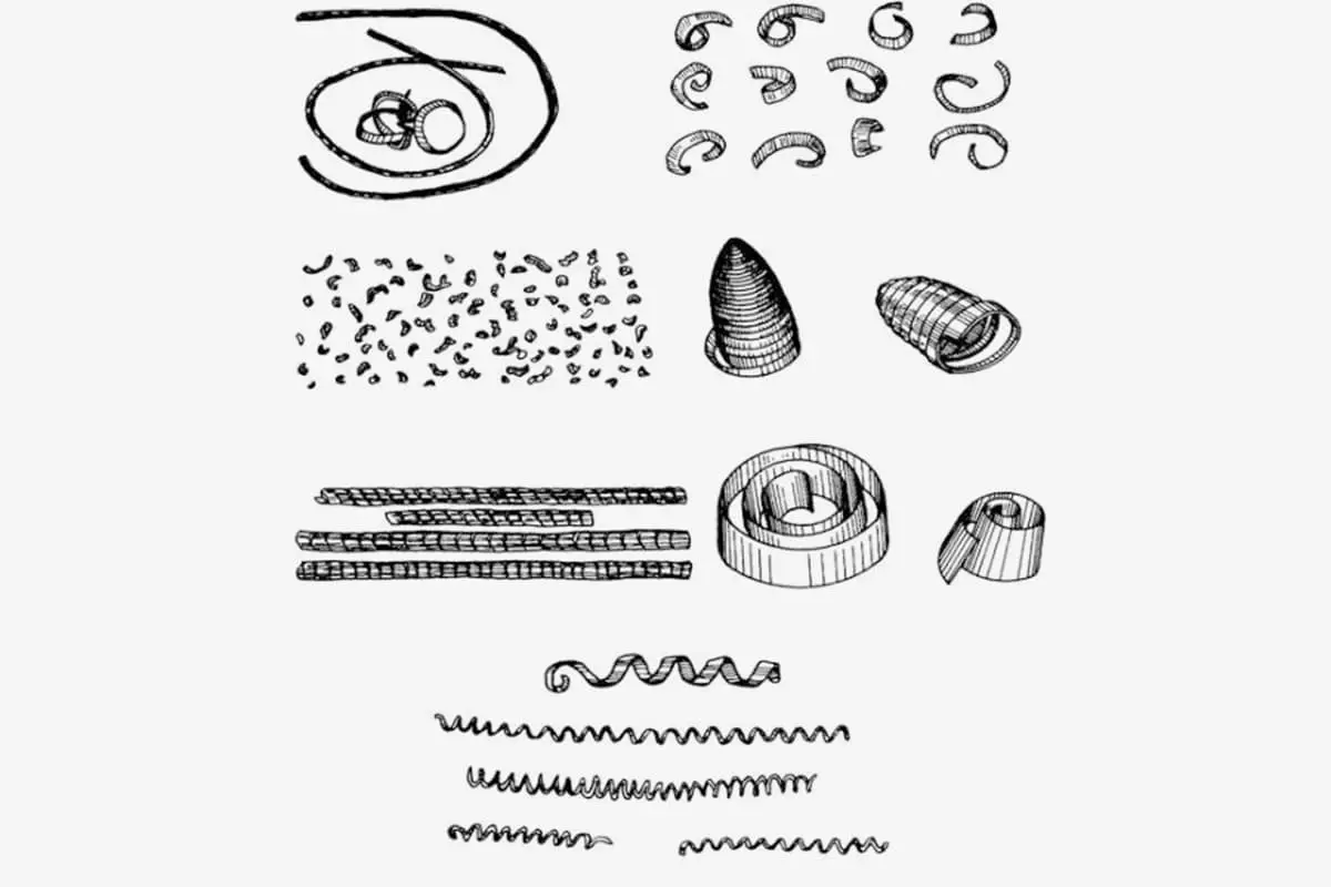
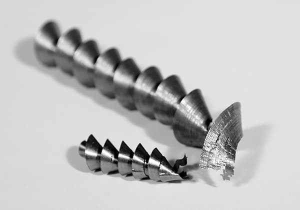
Have you ever thought about how tiny metal chips impact the machining process? In metal cutting, chip formation plays a crucial role in efficiency and safety. From spiral coils to…
Have you ever wondered how tiny holes are drilled with such precision in metal? This article explores the fascinating world of drilling, revealing the secrets behind various drill bits and…
Ever faced the frustration of a tiny drill bit snapping mid-task? This article dives into the common reasons behind small drill bit breakage, such as high cutting temperatures and manual…