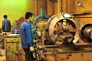
Compared to external cylindrical surface machining, the conditions for hole machining are much worse, making hole operations more challenging than external cylindrical machining. This is due to:
1) The tool size for hole machining is restricted by the hole’s dimensions, leading to poor rigidity, which can easily result in bending, deformation, and vibration.
2) When machining holes with a fixed-size tool, the size of the machined hole often directly depends on the tool’s size. Any manufacturing errors or wear in the tool will directly affect the precision of the machined hole.
3) During hole machining, the cutting area is inside the workpiece, resulting in poor chip removal and heat dissipation conditions, making it challenging to control machining accuracy and surface quality.
1. Drilling and Reaming
(1) Drilling
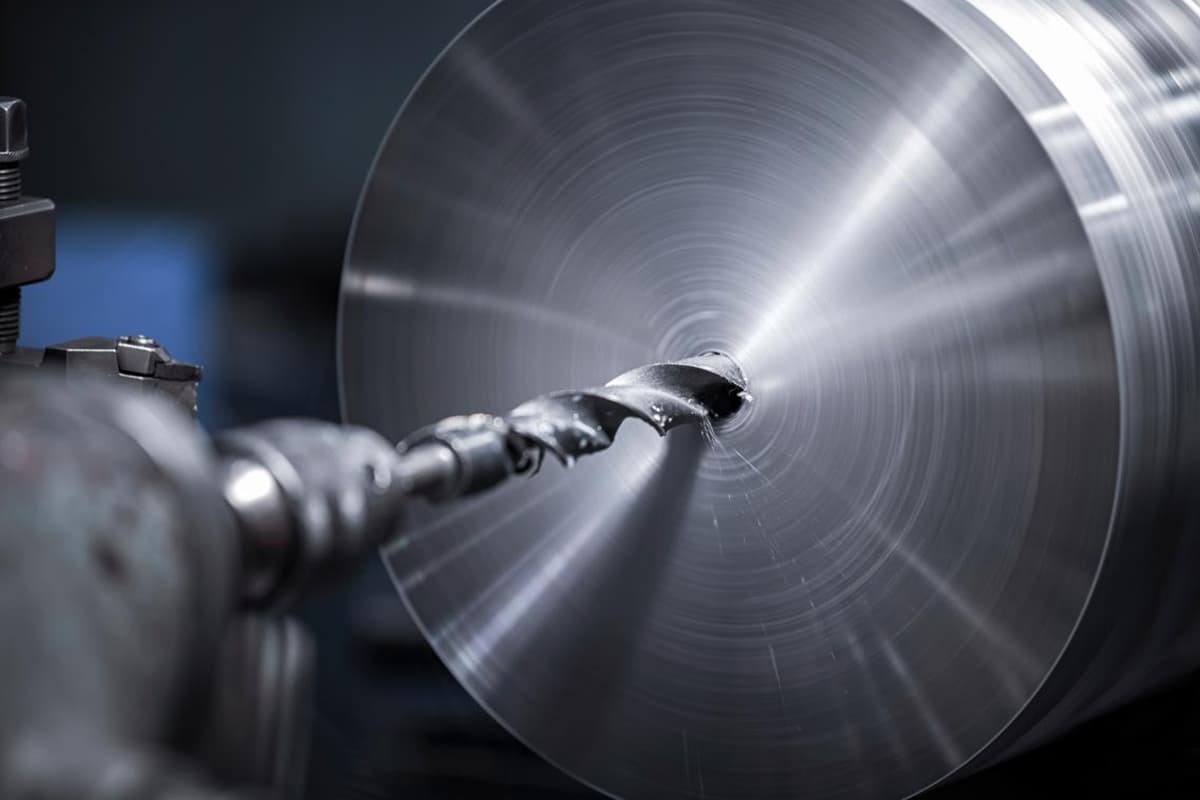
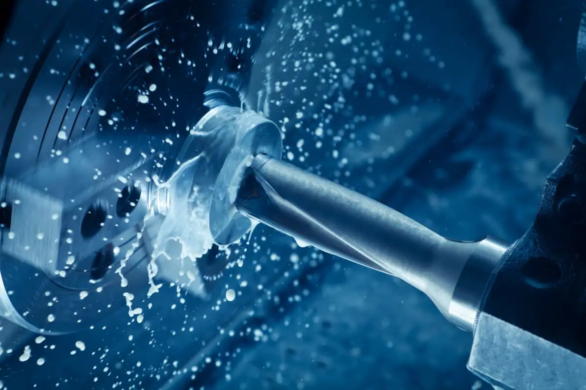
Drilling is the primary operation for making holes in solid materials, with a typical drilling diameter of less than 80mm. There are two methods of drilling: rotation of the drill bit and rotation of the workpiece.
The errors produced by these methods differ.
In the drill bit rotation method, the hole’s central axis may deviate or become misaligned due to the asymmetric cutting edges and insufficient rigidity of the drill bit, although the diameter remains essentially unchanged.
In contrast, with the workpiece rotation method, any misalignment of the drill will result in diameter changes, but the hole’s central axis remains straight.
Common drilling tools include twist drills, center drills, and deep-hole drills. The most frequently used is the twist drill, with diameter specifications ranging from Φ0.1-80mm.
Due to design limitations, drill bits exhibit low bending and torsional rigidity. Coupled with poor centering, the precision of drilling is usually only within IT13~IT11.
The surface roughness is also relatively high, typically between Ra 50~12.5μm. Drilling is primarily used for holes with lower quality requirements, such as bolt holes, threaded bottom holes, and oil holes.
For holes demanding higher precision and surface quality, subsequent operations like reaming, boring, or grinding should be applied.
(2) Reaming
Reaming is used to further process holes already drilled, cast, or forged to enlarge their diameter and improve their machining quality.
It can serve as a pre-machining step for precision hole machining or the final process for holes with lower requirements. Reamers resemble twist drills but have more teeth and lack cross-cutting edges.
Compared to drilling, reaming has the following characteristics:
1) Reamers have multiple teeth (3-8) ensuring better guidance and more stable cutting.
2) Without cross-cutting edges, reamers provide better cutting conditions.
3) Due to smaller machining allowances, chip grooves can be shallower, and the reamer’s core can be thicker, ensuring higher strength and rigidity.
The precision of reaming is generally between IT11~IT10, with surface roughness ranging from Ra 12.5~6.3μm. Reaming is often used for holes with diameters less than 30mm.
For larger diameter holes (D ≥30mm), a smaller drill (0.5-0.7 times the hole diameter) is initially used, followed by the corresponding reamer to improve machining quality and efficiency.
Besides cylindrical holes, special reamers can be used to machine countersunk holes and flat end faces. They typically feature a guiding column using a pre-machined hole for guidance.
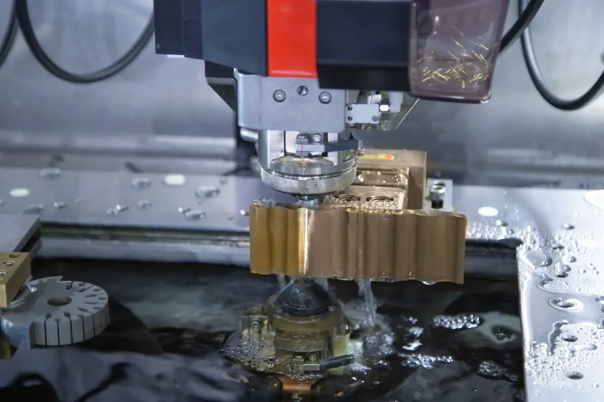
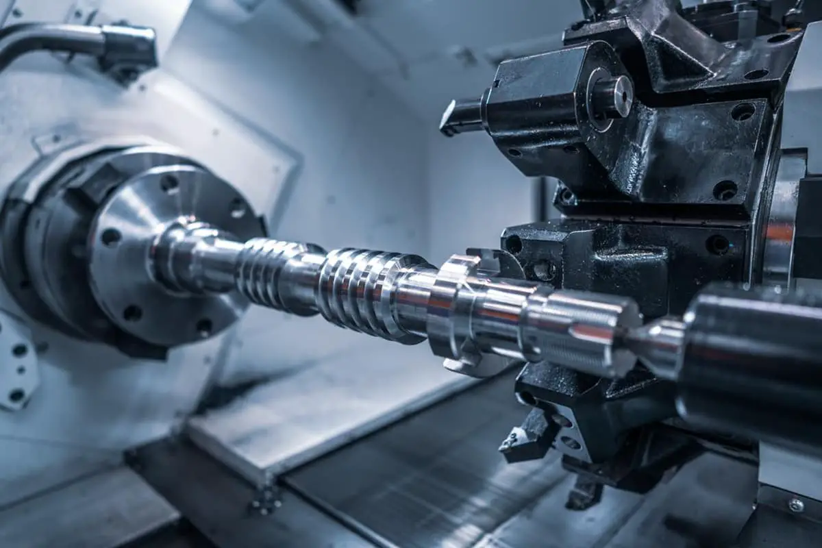
2. Boring
Boring is one of the precision machining methods for holes and is widely applied in manufacturing.
For smaller holes, compared to internal cylindrical grinding and fine boring, reaming is a more economical and practical method.
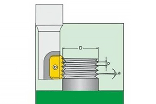
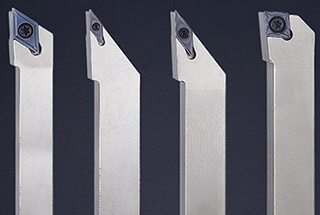
(1) Boring Tools
Boring tools typically come in two types: hand-operated and machine-operated. Hand-operated tools have a straight handle with a longer working part, providing better guidance. Machine-operated tools come with either a handle or a socket design. Boring tools can machine both cylindrical and tapered holes.
(2) Boring Process and Applications
The amount of material left for boring significantly influences the bore quality. Too much material increases tool load and wear, resulting in poor surface finish and dimensional tolerance.
Too little material won’t remove tool marks from the previous operation, failing to improve the hole quality.
Generally, rough boring requires a 0.35~0.15mm allowance, while fine boring requires 0.15~0.05mm.
To prevent chip accumulation, boring typically uses lower cutting speeds (for high-speed steel tools working on steel and cast iron, v<8m/min).
The feed rate depends on the hole diameter, with larger holes demanding higher feed rates, typically between 0.3~1mm/r for high-speed steel tools on steel and cast iron.
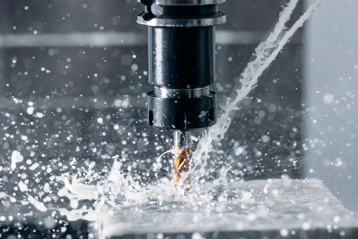
Proper cutting fluids are essential during boring for cooling, lubrication, and chip removal to avoid chip accumulation and ensure timely chip removal.
Compared to grinding and precision boring, reaming offers higher production rates and easier precision maintenance.
However, reaming can’t correct positional errors in the hole’s axis, which must be ensured by the previous operation. Reaming is unsuitable for stepped holes and blind holes.
The precision of reamed holes is usually between IT9~IT7, with surface roughness ranging from Ra 3.2~0.8μm.
For medium-sized holes requiring higher precision (like IT7), a drill-ream-bore sequence is a typical manufacturing approach.
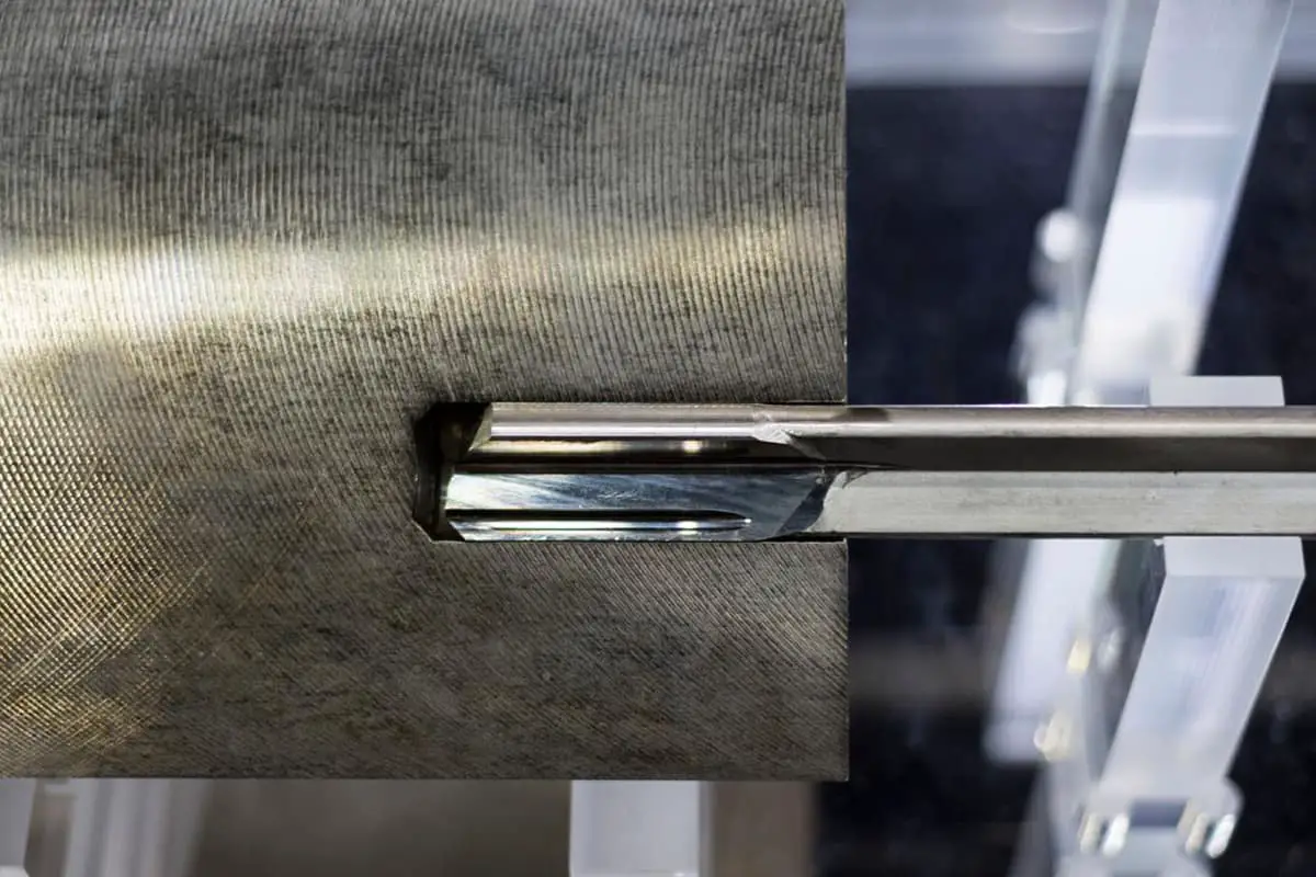
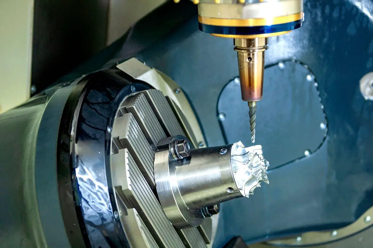
3. Trepanning
Trepanning is a machining method that enlarges pre-fabricated holes using a cutting tool. This operation can be performed on both a trepanning machine and a lathe.
1. Methods of Trepanning
There are three distinct methods of trepanning.
1) The workpiece rotates while the tool advances linearly. This method is primarily used on lathes.
A characteristic of this method is that the centerline of the hole machined aligns with the rotation axis of the workpiece.
The roundness of the hole depends mainly on the accuracy of the lathe’s main spindle rotation, while the axial geometric error is influenced by the precision of the tool’s feed direction relative to the workpiece’s rotation axis.
This method is ideal for machining holes that require concentricity with external surfaces.
2) The tool rotates while the workpiece advances linearly. The spindle of the trepanning machine drives the tool rotation, and the worktable moves the workpiece forward.
3) The tool rotates and advances simultaneously. In this method, the overhang length of the trepanning bar changes, causing variable forces and deformations on the bar. The hole diameter near the spindle box is larger than further away, resulting in a tapered hole.
Additionally, as the overhang length increases, bending deformities due to the weight of the spindle also increase, causing bending in the machined hole’s axis. This method is suitable only for shorter holes.
2. Diamond Trepanning
Compared to general trepanning, diamond trepanning features less back cutting, smaller feed rates, and higher cutting speeds.
It can achieve high machining accuracy (IT7 to IT6) and a very smooth surface finish (Ra between 0.4 and 0.05 μm). Initially, diamond trepanning was performed with diamond tools, but now tungsten carbide, CBN, and synthetic diamond tools are commonly used.
It is primarily used for non-ferrous metals but can also be employed for cast iron and steel.
Standard cutting parameters for diamond trepanning are:
- Back cutting for pre-trepanning: 0.2 to 0.6mm,
- Final trepanning: 0.1mm;
- Feed rate: 0.01 to 0.14mm/rev;
- Cutting speeds: 100 to 250m/min for cast iron, 150 to 300m/min for steel, and 300 to 2000m/min for non-ferrous metals.
To ensure high precision and surface quality in diamond trepanning, the machine (diamond trepanning machine) must have high geometric accuracy and rigidity.
The main spindle bearing typically uses precise angular contact ball bearings or hydrostatic sliding bearings, and high-speed rotating components must be finely balanced.
Moreover, the feed mechanism must operate very smoothly to guarantee steady, low-speed feed movement of the worktable.
Diamond trepanning offers excellent machining quality and productivity. It’s extensively used for the final machining of precision holes in mass production, such as engine cylinder holes, piston pinholes, and main spindle holes on machine tool headstocks.
However, it’s worth noting that when machining ferrous metal products with diamond trepanning, only tools made of tungsten carbide or CBN should be used.
Diamond tools are unsuitable due to the high affinity between carbon atoms in diamond and ferrous elements, leading to reduced tool life.
3. Trepanning Tools
Trepanning tools can be categorized into single-edged and double-edged tools.
4. Characteristics and Applications of Trepanning
Compared to the drilling-expanding-reaming process, trepanning isn’t limited by tool size. It has a strong ability to correct errors, allowing for multiple tool passes to adjust for initial hole misalignments.
Moreover, it maintains high positional accuracy with respect to the reference surface.
When contrasted with external turning, trepanning faces challenges such as reduced rigidity of the tool system, greater deformations, inadequate cooling and chip removal conditions, and significant thermal deformations of both the workpiece and tool. This results in lower machining quality and productivity for trepanning than external turning.
From the above analysis, it’s clear that trepanning offers a broad processing range, capable of machining various hole sizes and precision grades.
For large diameter holes requiring high dimensional and positional accuracy, trepanning is often the sole machining option.
Its machining accuracy ranges from IT9 to IT7. Trepanning can be performed on trepanning machines, lathes, milling machines, and other machine tools, offering versatility and widespread application in production.
In high-volume production, trepanning templates are often used to enhance efficiency.
4. Honing
(1) Principles of Honing and Honing Head
Honing is a finishing process that utilizes a honing head equipped with grinding sticks (whetstones) to smooth holes.
During honing, the workpiece remains stationary while the honing head, driven by the machine’s main spindle, rotates and reciprocates in a linear manner.
The grinding sticks exert pressure on the workpiece’s surface, removing an extremely thin layer of material, resulting in an intersecting crosshatch pattern.
To prevent the repetitive tracking of the abrasive grits, the revolutions per minute of the honing head rotation and its reciprocations should be coprime.
The angle of the crosshatch pattern is associated with the reciprocating speed and the circumferential speed of the honing head. The size of this angle affects the honing quality and efficiency.
Typically, a coarser angle is used for rough honing, and a finer angle for finish honing. To facilitate the removal of broken abrasives and chips, reduce cutting temperature, and enhance the machining quality, ample cutting fluid should be used during honing.
To ensure even honing across the hole’s wall, the grinding stick should travel beyond both ends of the hole by a certain extent.
To ensure uniform honing and minimize the impact of spindle rotation errors on machining accuracy, most honing heads are floatingly connected to the main spindle.
Various structures like manual, pneumatic, and hydraulic are adopted for the radial expansion adjustments of the grinding sticks in the honing head.
(2) Technical Features and Application Scope of Honing
1) Honing achieves high dimensional and geometric accuracy. The machining accuracy ranges from IT7 to IT6. The roundness and cylindricity errors of the hole can be controlled within a tight range. However, honing does not improve the positional accuracy of the processed hole.
2) Honing produces a superior surface finish with a surface roughness Ra of 0.2~0.25μm and a very minimal altered metal layer depth of 2.5~25μm.
3) Compared to grinding speeds, the circumferential speed of the honing head might not be high (vc=16~60m/min).
However, due to the large contact area between the grinding stick and the workpiece, and a relatively high reciprocating speed (va=8~20m/min), honing still maintains a high production rate.
Honing is extensively used in mass production for machining engine cylinders and precise holes in various hydraulic devices.
It typically handles holes with diameters of [specific size] or larger, and can machine deep holes with a length-to-diameter ratio greater than 10.
However, honing is not suitable for holes in non-ferrous metals with significant plasticity, nor can it process holes with keyways or spline slots.
5. Broaching
(1) Broaching and Broach Tool
Hole broaching is a high-production precision machining method executed with a specially designed broach tool on a broaching machine.
Broaching machines are categorized into horizontal and vertical types, with horizontal being the most prevalent.
During broaching, the broach tool performs a low-speed linear movement (primary motion).
Generally, the broach tool should have at least 3 working teeth engaged; otherwise, it may operate unstably and likely produce circular ripples on the workpiece surface.
To prevent excessive broaching force that could break the tool, the number of simultaneously working teeth should typically not exceed 6 to 8.
There are three distinct broaching techniques:
1) Layer-by-Layer Broaching:
This technique sequentially removes the workpiece’s machining allowance layer by layer. To facilitate chip breaking, the tool teeth are designed with interlocking chip-breaking grooves. Broach tools designed for this technique are called standard broaches.
2) Segmental Broaching:
The characteristic of this technique is that each metal layer of the machining surface is removed by a set of staggered teeth of nearly the same size (usually consisting of 2-3 teeth). Each tooth removes only a portion of a metal layer. Broaches designed for this method are termed as wheel-cutting broaches.
3) Combined Broaching:
This approach amalgamates the advantages of both layer-by-layer and segmental broaching. Coarse-cutting sections use segmental broaching, while fine-cutting sections adopt the layer-by-layer technique. This not only shortens the broach tool length, enhancing productivity but also achieves a better surface finish. Broaches designed for this method are known as combined broaches.
(2) Technical Features and Application Scope of Hole Broaching
1) The broach tool is multi-edged; in a single broaching stroke, it sequentially completes rough machining, finish machining, and polishing of the hole, making the process highly efficient.
2) Hole broaching accuracy largely depends on the precision of the broach tool. Under standard conditions, hole broaching accuracy can reach IT9 to IT7, and the surface roughness Ra can be between 6.3 to 1.6 μm.
3) During hole broaching, the workpiece is positioned by the hole being machined (the leading part of the broach tool serves as the positioning component). This makes it challenging to ensure positional accuracy between the hole and other surfaces. For rotational parts where the inner and outer circular surfaces require concentricity, broaching is usually done first, then other surfaces are machined using the hole as the reference.
4) Broach tools can not only machine round holes but also shape holes and spline holes.
5) Broach tools are fixed-size tools; they have complex shapes and are expensive, making them unsuitable for machining larger holes.
Hole broaching is frequently used in mass production for machining through-holes on small to medium-sized parts with diameters ranging from Ф10 to 80mm and hole depths not exceeding five times the diameter.