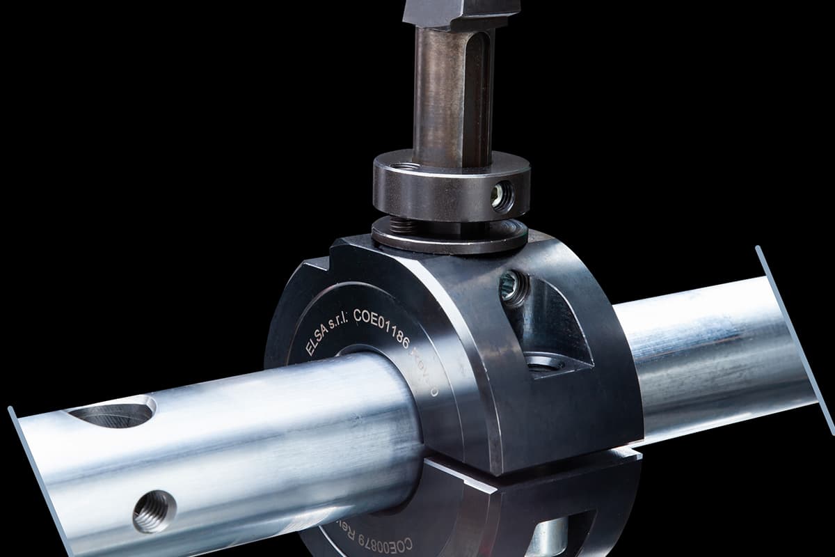
Hole machining is a familiar process, but what are the differences between drilling, reaming, countersinking, and boring? Let me explain today.
1. Drilling
Drilling is the initial process of creating holes in solid materials, typically with diameters less than 80mm. There are two methods of drilling: one involves rotating the drill bit, while the other rotates the workpiece. The errors produced by these two methods differ.
In the drill bit rotation method, due to asymmetric cutting edges and insufficient rigidity of the drill bit, the bit may deviate, causing the centerline of the hole to become skewed or not straight, but the diameter of the hole remains unchanged.
In contrast, when the workpiece rotates, deviation of the drill bit can cause a change in the hole diameter, yet the centerline remains straight.
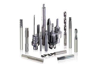
Common drilling tools include twist drills, center drills, and deep hole drills, with twist drills being the most widely used, ranging in diameter from 0.1 to 80 mm.
Due to structural limitations, drill bits have low bending and torsional stiffness, and poor centering capabilities, resulting in low drilling accuracy, typically between IT13 and IT11; surface roughness is also relatively high, generally between Ra 50 and 12.5 μm.
However, drilling has a high metal removal rate and cutting efficiency. It is primarily used for holes that do not require high precision, such as bolt holes, threaded bottom holes, and oil holes.
Holes requiring higher precision and surface quality should be finished with subsequent processes such as reaming, countersinking, boring, or grinding.
2. Reaming
Reaming is the process of further machining pre-drilled, cast, or forged holes to enlarge the diameter and enhance the quality of the hole. Reaming can serve as a pre-finishing operation before precision machining or as the final process for holes with less stringent requirements. Reamers are similar to twist drills but have more teeth and lack cross-cutting edges.
Compared to drilling, reaming has the following characteristics:
(1) Reamers have multiple teeth (3 to 8), providing good guidance and stable cutting;
(2) Reamers lack cross-cutting edges, which improves cutting conditions;
(3) The machining allowance is small, allowing for shallower chip flutes and a thicker core, resulting in stronger and more rigid tool bodies. The precision of reaming is generally between IT11 and IT10, with surface roughness values between Ra 12.5 and 6.3. Reaming is commonly used for holes with diameters less than 100 mm. When drilling larger holes (D ≥ 30 mm), it is common practice to pre-drill with a smaller drill bit (0.5 to 0.7 times the diameter of the hole) and then ream to the desired size, thereby improving the quality and efficiency of hole machining.
In addition to cylindrical holes, various special-shaped reamers, also known as counterbores, can be used to machine countersunk holes and flatten end faces. The front end of a counterbore often features a guiding column, which is directed by the hole already machined.
3. Countersinking
Countersinking is one of the precision machining methods for holes and is widely used in production. For smaller holes, compared to internal grinding or precision boring, countersinking is a more economical and practical method.
(1) Countersinks
Countersinks are generally divided into hand-operated and machine-operated types. Hand-operated countersinks have a straight shank with a longer working part, providing better guidance, and come in integral and adjustable outside diameter types.
Machine-operated countersinks come in shank and sleeve types. Countersinks can process not only round holes but also tapered holes with tapered countersinks.
(2) Countersinking Process and Application
The allowance for countersinking greatly impacts the quality of the finish. Too much allowance increases the load on the countersink, dulling the cutting edges quickly and making it difficult to achieve a smooth surface and maintain dimensional tolerances. Insufficient allowance fails to remove marks left by previous processes, thus not improving the hole’s machining quality.
The general allowance for rough countersinking is between 0.35 and 0.15 mm, while for fine countersinking, it is between 0.15 and 0.05 mm.
To prevent the formation of built-up edges, countersinking is typically performed at low cutting speeds (for high-speed steel countersinks machining steel and cast iron, v < 8 m/min). The feed rate depends on the diameter of the hole being machined; larger diameters require larger feed rates, with common feed rates for high-speed steel countersinks machining steel and cast iron between 0.3 and 1 mm/r.
Countersinking requires the use of appropriate cutting fluids for cooling, lubrication, and cleaning to prevent built-up edges and timely chip removal.
Compared to grinding and boring, countersinking offers higher productivity and easily maintains hole accuracy; however, it cannot correct positional errors of the hole axis, which should be ensured by the previous process. Countersinking is not suitable for machining stepped holes and blind holes.
The dimensional accuracy of countersinking is generally between IT9 and IT7, with surface roughness typically between Ra 3.2 and 0.8. For medium-sized holes with higher precision requirements (e.g., IT7 grade holes), the typical machining sequence in production is drilling—reaming—countersinking.
4. Boring
Boring is a machining process that enlarges a pre-drilled hole with a cutting tool. This operation can be performed on both boring machines and lathes.
1. Boring Methods
There are three different boring methods:
a) Workpiece rotation with tool feed motion: This method is commonly used on lathes. The process ensures that the axis of the bored hole aligns with the rotational axis of the workpiece. The roundness of the hole primarily depends on the rotational accuracy of the machine spindle, while the axial geometric shape error is mainly determined by the precision of the tool feed direction relative to the workpiece’s rotational axis. This method is suitable for boring holes that require concentricity with the outer cylindrical surface.
b) Tool rotation with workpiece feed motion: The boring machine’s spindle drives the boring tool to rotate, while the worktable moves the workpiece forward.
c) Tool rotation with feed motion: When using this method, the projection length of the boring bar changes, as does the deformation under load, resulting in a tapered hole with a larger diameter near the spindle box and a smaller diameter further away. Additionally, as the boring bar’s projection length increases, the bending deformation caused by the spindle’s own weight also increases, which causes a corresponding bend in the axis of the hole being machined. This method is only suitable for boring short holes.
2. Diamond Boring
Compared to general boring, diamond boring is characterized by a smaller back-cutting amount, smaller feed rate, and higher cutting speed. It can achieve high machining precision (IT7 to IT6) and a very smooth surface finish (Ra 0.4 to 0.05). Initially, diamond boring was performed using diamond boring tools, but now commonly uses hard alloy, CBN, and synthetic diamond tools. It’s mainly used for machining non-ferrous metal workpieces and can also be applied to cast iron and steel workpieces.
The typical cutting parameters for diamond boring are: back-cutting amount of 0.2 to 0.6mm for rough boring and 0.1mm for finish boring; feed rate of 0.01 to 0.14mm/r; cutting speed of 100 to 250m/min for cast iron, 150 to 300m/min for steel, and 300 to 2000m/min for non-ferrous metals.
To ensure high machining precision and surface quality in diamond boring, the machine (diamond boring machine) must have high geometric accuracy and rigidity. The main spindle bearings often use precision angular contact ball bearings or hydrostatic sliding bearings, and high-speed rotating parts must be precisely balanced. Furthermore, the feed mechanism must move smoothly to ensure that the worktable can perform stable and slow feed movements.
Diamond boring is widely used in mass production for final precision hole machining, such as engine cylinder bores, piston pin holes, and main spindle holes in machine tool spindle boxes. However, it’s important to note that when machining ferrous metals with diamond boring, one should use boring tools made of hard alloy or CBN instead of diamond, as the carbon atoms in the diamond bond strongly with the iron group elements, reducing tool life.
3. Boring Tools
Boring tools can be categorized into single-edge and double-edge boring tools.
4. Technological Features and Application Scope of Boring
Compared to the drilling-expanding-reaming process, boring is not limited by tool size and has a strong ability to correct errors. It can correct initial hole axis deviation through multiple passes and maintain a high positional accuracy with the locating surface.
In comparison to external turning, boring has less rigidity in the tool bar system, greater deformation, poor heat dissipation, and chip removal conditions, and both the workpiece and tool experience significant thermal deformation. Consequently, the machining quality and production efficiency of boring are not as high as those of external turning.
In summary, boring has a wide range of applications, capable of machining various sizes and precision levels of holes. It is almost the exclusive method for holes with large diameters and high dimensional and positional accuracy requirements. The machining precision of boring ranges from IT9 to IT7, and the surface roughness is Ra. Boring can be performed on boring machines, lathes, milling machines, and other types of machine tools, offering the advantage of flexibility. In mass production, to improve boring efficiency, boring jigs are often used.
5. Honing
1. Honing Principle and Honing Tool
Honing is a method of finish machining holes with a honing tool equipped with abrasive sticks (oilstones). During honing, the workpiece remains stationary while the honing tool, driven by the spindle of the machine tool, rotates and reciprocates linearly.
In the honing process, the abrasive sticks apply a certain pressure to the surface of the workpiece, removing an extremely thin layer of material, resulting in a crosshatched pattern on the surface. To ensure the abrasive particles do not follow the same path, the number of rotations per minute of the honing tool and the number of reciprocating strokes per minute should be relatively prime.
The crossing angle θ of the honing pattern relates to the reciprocating speed (va) and the circumferential speed (vc) of the honing tool. The size of angle θ affects the quality and efficiency of honing; typically, θ is set to 40-60° for rough honing and finer for precision honing. To facilitate the expulsion of broken abrasive particles and chips, reduce cutting temperature, and improve processing quality, ample cutting fluid should be used during honing.
To ensure uniform machining of the hole wall, the stroke of the abrasive sticks should extend beyond both ends of the hole. To ensure even honing allowance and minimize the impact of spindle rotation errors on machining accuracy, a floating connection is commonly used between the honing tool and the machine spindle.
Radial expansion and contraction adjustments of the honing tool’s abrasive sticks can be manual, pneumatic, hydraulic, and other structures.
2. Technological Features and Application Range of Honing
1) Honing achieves high dimensional and shape accuracy, with processing precision at the IT7-IT6 level. The roundness and cylindricity errors of the hole can be controlled within a very tight range. However, honing does not improve the position accuracy of the machined hole.
2) Honing achieves a high surface quality, with surface roughness (Ra) ranging from 0.2 to 0.025μm and an extremely shallow depth of the altered defect layer in the metal surface (2.5-25μm).
3) Although the circumferential speed of the honing tool is not high (vc=16-60m/min) compared to grinding speeds, the larger contact area between the abrasive sticks and the workpiece and the relatively high reciprocating speed (va=8-20m/min) still allow honing to maintain high productivity.
Honing is widely used in mass production for machining precision holes in engine cylinders and various hydraulic devices. The range of hole diameters typically starts from 5mm or larger, and honing can process deep holes with length-to-diameter ratios greater than 10. However, honing is not suitable for machining holes in nonferrous metal workpieces with high plasticity, nor can it process holes with keyways or splines.
6. Broaching
1. Broaching and Broaches
Broaching is a highly productive precision machining process performed on a broaching machine using specially designed broaches. There are two main types of broaching machines: horizontal and vertical, with horizontal being the most common.
During broaching, the broach performs a slow linear motion (the primary motion). The number of broach teeth engaged simultaneously should generally be no less than three to ensure stability; otherwise, uneven cutting can create ring-shaped ripples on the workpiece surface. To prevent excessive broaching forces that could break the broach, the number of cutting teeth working at the same time should generally not exceed six to eight.
There are three distinct broaching methods, described as follows:
1) Layer-by-layer broaching involves sequentially cutting the excess material from the workpiece layer by layer. To facilitate chip breaking, the broach teeth are ground with interlocking chip-breaker grooves. Broaches designed for this method are called plain broaches.
2) Segmental broaching is characterized by each layer of the machined surface being cut by a group of similarly sized, staggered teeth (typically 2 to 3 teeth per group). Each tooth only removes part of a single metal layer. Broaches designed for this method are called rotary-style broaches.
3) Combined broaching combines the advantages of both layer-by-layer and segmental broaching. The roughing portion uses segmental broaching, while the finishing portion uses layer-by-layer broaching. This not only shortens the broach length and improves productivity but also achieves better surface quality. Broaches designed for this method are called combination broaches.
2. Technological Characteristics and Applications of Broaching
1) Broaches are multi-edge tools that can sequentially perform roughing, finishing, and burnishing of a hole in a single broaching stroke, resulting in high production efficiency.
2) The precision of broaching primarily depends on the accuracy of the broach. Under normal conditions, broaching can achieve tolerances of IT9 to IT7, with surface roughness (Ra) reaching 6.3 to 1.6 μm.
3) During broaching, the workpiece is self-located by the hole being machined (the leading part of the broach serves as the positioning element), making it challenging to ensure the positional accuracy of the hole relative to other surfaces; for rotational parts requiring concentricity between the inner and outer surfaces, broaching is often performed first, followed by machining other surfaces based on the hole as a reference.
4) Broaches can machine not only round holes but also shaped holes and spline holes.
5) Broaches are fixed-size tools with complex shapes and high costs, making them unsuitable for machining large holes.
Broaching is commonly used in mass production for machining through-holes in small to medium-sized parts with diameters ranging from 10 to 80mm and hole depths not exceeding five times the diameter.