History of Development of Chip Breaker Grooves
With the development of indexable cutting tool technology and powder metallurgy technology, chip breaker grooves have become increasingly complex and diverse in their shapes and functions. In addition to the traditional straight, diagonal, and curved edge grooves, various shapes of bumps, depressions, and curved grooves have emerged.
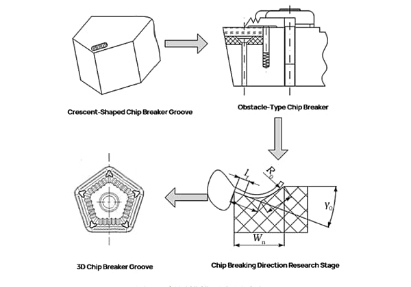
The history of chip breaker groove development can be summarized into four stages: the crescent-shaped chip breaker groove stage, the obstacle-type chip breaker stage, the chip breaking direction research stage, and the 3D chip breaker groove stage, as shown in the figure below.
In the 1950s, the appearance of a crescent-shaped depression on the tool face during cutting made chip breaking easier. Inspired by this, people would pre-grind a groove similar to a crescent-shaped depression on the tool face to facilitate chip breaking, or add an additional chip breaker device on the tool face, which are generally called traditional chip breaker grooves and obstacle-type chip breakers, respectively.
At that time, the chip breaking theory was not yet fully developed, and people generally used the “trial and error method” to design groove shapes, which was very inefficient.
In the 1960s, groove shape design focused on the analysis, comparison, and optimization of traditional chip breaker grooves and obstacle-type chip breakers. The influence of chip breaker groove shapes on chip shape and size was studied extensively, enabling chip breaking to occur over a wider range of cutting conditions.
In the 1970s, with the maturity of molding technology, groove machining changed its traditional grinding wheel method, and groove shape design became more complex and versatile. At this time, groove design mainly considered reducing the energy loss of chip flow and machining process, and typical groove structures such as inclined grooves and facet angle designs emerged.
In the late 1980s, the rapid development of 3D complex chip breaker grooves greatly increased the tool life and reliability compared to traditional 2D chip breaker grooves, reduced machine and workpiece vibrations, lowered machining temperatures, and improved workpiece machining quality.
The 3D chip breaker groove has a rich variety of forms, mainly including two-stage grooves and wavy edges. Thanks to the development of 3D chip breaker grooves, the application of CNC contouring machining has also been continuously enhanced. For example, when turning a spherical workpiece, a 3D chip breaker groove tool can ensure high machining accuracy throughout the entire process.
Classification of Chip Breaker Groove Shapes
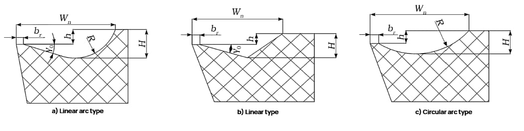
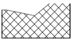
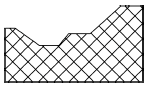
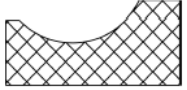
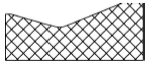
Traditional chip breaker grooves can be classified into three types: straight-line, arc-shaped, and straight-line arc-shaped, as shown in the schematic diagram of groove structures below.
The chip breaking effect can be measured to some extent by the curl radius of the chip. Moreover, the smaller the curvature of the chip breaker groove shape, the smaller the curl radius of the chip, the greater the chip deformation, and the more likely it is to break.
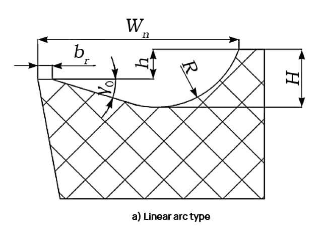
The straight-line arc-shaped chip breaker groove is composed of one straight section and one arc section. The straight section is used to guide the chip out, and the arc section at the end makes the chip curl, which leads to deformation and breaking.
The smaller the diameter of the arc section, the easier it is for the chip to break.
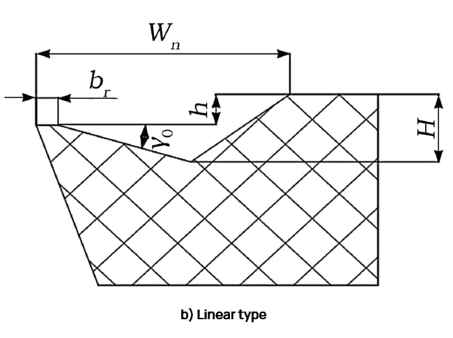
The straight-line chip breaker groove is formed by the intersection of two straight lines, and its groove bottom angle is the supplement angle of the chip wedge angle.
In the model shown in figure (b), the groove bottom angle replaces the role of the groove bottom arc radius R in the models shown in figures (a) and (c). That is, the chip will hit the back surface of the groove before the intersection of the two straight lines, and then directly curl and deform. The smaller the groove bottom angle, the smaller the curvature and curl radius of the chip, and the more likely it is to break.
Compared to the previous two types, the arc-shaped chip breaker groove has a relatively large front angle. The increase in the front angle means that the curl radius of the chip decreases, and the deformation of the chip increases, making it more likely to break. Therefore, it is often used for cutting highly ductile materials such as purple copper.
Moreover, due to its full arc structure, the groove depth is relatively small, and the chip flow is smoother, making it more practical in engineering applications.
Analysis of Chip Breaker Groove Parameters
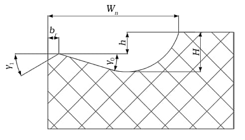
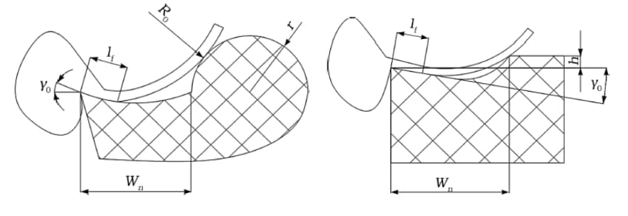
The basic structure of chip breaker groove is shown in the figure below.
This article takes the straight arc-shaped chip breaker groove as an example to illustrate the influence of geometric parameters of chip breaker groove on chip performance.
In the figure, br is the negative chamfer width, Wn is the normal groove width (referred to as groove width) of the main cutting edge chip breaker groove, γ0 is the front angle of the chip breaker groove, γ1 is the front angle of the negative chamfer, h is the blade height, and H is the depth of the chip breaker groove (referred to as groove depth).
Changes in these parameters will directly affect the groove type and chip performance of the chip breaker groove. Based on literature, the following conclusions can be drawn:
1. Setting a negative chamfer can enhance the strength of the cutting edge. The wider the negative chamfer, the blunter the cutting edge, and the greater the cutting force. If the width of the negative chamfer is too small, the strength of the cutting edge will be reduced, affecting the tool life. Therefore, there is an optimal value for the width of the negative chamfer.
2. The larger the front angle of the chip breaker groove, the smaller the curl radius of the chip, the greater the deformation of the chip, and the easier it is for the chip to break.
3. Groove width and groove depth are the main factors that affect chip breaking. When designing the geometry of the chip breaker groove, the influence of groove width and groove depth on chip breaking is interrelated. When selecting the geometric parameters of the groove type, the ratio of groove width to groove depth is usually considered as a parameter.
Generally, if the groove width is too large, the chip is not easy to break, while if the groove width is too small, it is easy to cause chip blockage. Therefore, a larger groove width can be used for rough machining, while a smaller groove width can be used for finishing. With the groove width determined, a smaller value should be selected for the groove depth.
4. The influence of the blade height on chip performance is also affected by the groove depth. With the same groove depth, reducing the blade height will increase the front angle, reduce the deformation of the chip, reduce the cutting force, and make the chip less likely to break. However, increasing the blade height will increase the obstruction of the groove back to the chip, making the chip more likely to break, and reducing the strength of the blade edge.
5. The relief angle is the angle between the tangent of the groove back and the front face of the tool. The larger the relief angle, the easier it is for the chip to break.
In addition to the front angle of the chip breaker groove having a significant impact on chip performance, other angle parameters also have some influence, among which the primary clearance angle and rake angle have the greatest influence.
The primary clearance angle mainly affects the thickness and width of the cutting. When the primary clearance angle increases, the chip becomes narrower and thicker, and is more likely to break.
The rake angle mainly affects the direction of chip flow. When the rake angle is greater than zero, the chip flows towards the unprocessed surface and can be used for finishing. When the rake angle is less than zero, the chip flows towards the processed surface, affecting the surface quality. Considering the tool size, the rake angle is generally selected between 5° and 15°.
Classic Chip Breaker Designs and Their Characteristics
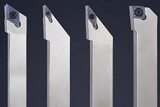
This article selects the hard alloy (back angle 0°) cutting tools of 8 companies with high market share in the current market (Mitsubishi, Kyocera, Sumitomo, Dege, Sandvik, Kennametal, Tungaloy, and Walter). Based on their geometric shapes, 9 basic slot types and their design characteristics are summarized and analyzed in the following.
Linear type
Typical cutting tool with a straight, flat-bottomed structure.
The negative rake angle and the straight section in the middle ensure the strength of the cutting edge, allowing for a larger front angle.
Typical cutting tool with a straight pointed tip and flat bottom.
The front angle is generally smaller to ensure the strength of the cutting edge. The cutting edge height is sufficient for easy chip breaking.
Typical cutting tool with a double straight slot structure.
The double slot structure is used for contour turning.
Circular arc type
Typical cutting tool with a single circular arc structure.
The circular arc structure arranges the front angle from large to small, while ensuring the strength of the cutting edge.
Typical cutting tool with a double circular arc structure.
The circular arc structure. The convex surface on the back of the slot provides elastic chip breaking, allowing for a larger feed rate compared to rigid chip breaking.
Linear arc type
Typical cutting tool with a straight-circular-straight structure.
The negative rake angle enhances the strength of the cutting edge, while a larger front angle ensures sharpness but may not be conducive to chip breaking. When the front angle, slot width, and cutting edge height are constant, a larger width-to-depth ratio makes chip breaking easier.
Typical cutting tool with a straight-circular structure.
Negative rake angle, large front angle. When the front angle, slot width, and cutting edge height are constant, a larger width-to-depth ratio makes chip breaking easier.
Typical cutting tool with a circular-straight structure.
The front end of the slot is designed to be circular, while ensuring the strength of the cutting edge.
Typical cutting tool with a straight-circular (double slot) structure.
The convex back design of the slot provides elastic chip breaking, allowing for a larger feed rate compared to rigid chip breaking. The double slot structure is used for contour machining and is often used in precision machining.
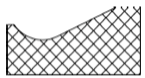
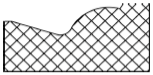
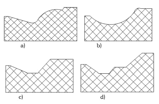
Among the 9 basic slot types listed in the table above, 4 slot structures have been modified from previous designs to improve chip breaking performance. The 4 typical slot structures are shown in the following figure, with a classic example of each slot type listed:
a) The slot type in Figure A is a straight-circular (double slot) structure. Compared with the traditional concave curved surface straight-circular slot, this structure symmetrically sets the circular arc part of the slot back, using it as a convex elastic chip breaking ring, allowing for a larger feed rate compared to rigid chip breaking.
Using this slot type, the contact area between the chips and the chip breaking groove in the cross-sectional direction is smaller. Additionally, compared with the traditional concave curved surface chip breaking groove, the chip curling radius is smaller, making it easier to break the chips.
Moreover, the convex surface can increase the lateral curling of the chips, resulting in greater deformation of the chips, making them easier to break.
b) The slot type in Figure B is a double circular arc structure. The characteristic of the double circular arc structure is that a small convex elastic chip breaking ring is set at the end of the slot back, and the front end of the circular arc structure slot type arranges the front angle from large to small.
Compared with the straight structure, considering that a small front angle will increase the deformation of the chips and make the cutting easier to break, the circular arc structure at the front end of the slot type is more conducive to chip breaking. Therefore, it is unnecessary to set a large convex elastic chip breaking ring in the slot back part. Setting a small convex surface at the end can achieve similar effects.
c) The slot type in Figure C is a straight-flat-bottomed structure. The traditional straight-pointed bottom structure concentrates stress at the bottom, which affects the strength of the cutting edge. Changing it to a flat-bottomed structure can overcome the problem of low cutting edge strength.
Additionally, because it is a flat-bottomed structure, a larger front angle can be set, thereby reducing cutting forces and cutting temperatures. Therefore, this structure is more suitable for cutting plastic materials.
d) The slot type in Figure D is a double straight slot structure. The double straight slot structure has two slots and belongs to a double slot structure.
Considering that in rough machining, a large feed rate and cutting depth are required to ensure efficiency, while in precision machining, a small slot width and an appropriate slot depth are required to ensure good machining accuracy, the double slot structure is designed such that the chips are broken in the first deep slot in precision machining and in the second slot in rough machining.
The advantage of this structure is its composite structure, which provides a wider range of machining.
In addition to the aforementioned designs, there are many slot type designs with special structures. Moreover, more designs that are more suitable for specific situations can be added based on traditional slot shapes to make them more manufacturable.
For example, in the design of a three-dimensional chip breaking groove slot type, the cutting edge can be designed as a curve or a waveform (such as Toshiba’s 37-type chip breaking groove and Sandvik’s PF-type chip breaking groove).
Alternatively, the traditional concave curved surface chip breaking groove can be changed to a convex surface (such as Sumitomo’s GH-type chip breaking groove and Sandvik’s MM-type chip breaking groove) to achieve the purpose of elastic chip breaking and reduced chip breakage during large feed rates. Friction-reducing structures can also be used in the design.
This article provides two typical chip breaking groove slot types with special designs, as shown in the figure below.
Evaluation of chip breaking performance
The curling radius of chips is a universal measure of the chip break effect.
Chip curling can take the form of 2D or 3D curling, with 2D curling mainly consisting of upward curling and lateral curling. Currently, there has been extensive research on the theory of 2D upward curling.
For example, the predicted curling radius of straight-type and straight arc-type chip slots was examined. The curling of straight-type slot is illustrated in the diagram below:
The curling of chips for a convex surface slot is illustrated in the following left diagram, and the curling of chips for a straight arc-type slot is illustrated in the right diagram.
The formula for calculating the curling radius of chips is very complex and will not be explained in detail here.
The chip slot is based on changing the chip curling radius to improve chip performance when using the chip curling radius to measure chip performance.
After comparing with the empirical formulas summarized by previous researchers, the original text concludes that the curling radius of chips is proportional to the slot width and inversely proportional to the front angle, i.e., smaller slot widths and larger front angles are advantageous for chip breakage.