Imagine your car’s engine suddenly stops working, leaving you stranded. The culprit? A malfunctioning gearbox. This comprehensive guide to gearbox operation explores everything from installation and safety precautions to maintenance tips. By understanding the intricacies of gearbox management, you’ll learn how to prevent breakdowns, ensuring smooth and reliable performance. Dive in to discover essential practices for transportation, storage, and regular upkeep of gearboxes, crucial for anyone handling these complex machines.
Before installation and use, please thoroughly read this manual. The gearbox has been subjected to no-load testing before leaving the factory, and load testing has been performed as per contract requirements.
Upon shipping, the oil in the gearbox has been drained, and packaging has been done according to the contract stipulations. Unless otherwise specified in the contract (such as if the customer requests assistance with installation), any actions taken with the gearbox after it leaves the factory exceed the control of our plant.
Hence, this manual especially emphasizes and clarifies the following responsibilities of the user:
● Transportation
● Storage and corrosion prevention
● Installation
● Overdue storage
● Disassembly
● Pre-start checks
● Operation and maintenance
2. Unpacking
During the unpacking process, verify if the product’s model and specifications are correct; check whether all components and accessories are included and if the technical documents are complete.
Inspect for any damages or rust that may have occurred during transportation or storage. (If any damage or rust is discovered, ascertain its cause and proceed with repairs. The quality of the repairs must be mutually approved by the manufacturer and the user before the product can be used).
3. Technical Specifications
3.1 Nameplate
All crucial technical parameters are embodied on the nameplate, which predominantly includes the following details:
1 Gearbox model: FD3300C
2 Power: 3300KW
3 Gear ratio: 94.972
4 Input speed: 12.6 rpm
5 Output speed: 1200 rpm
6 Weight: 29500Kg
3.2 Field of Application
This gearbox is exclusively for wind turbine applications. Its design and manufacturing process strictly adhere to the load and conditions outlined in the technical specifications provided by the client.
The gearbox manufacturer accepts no responsibility for any issues that may arise from usage beyond these conditions. Any modifications made without the manufacturer’s consent will not be accepted.
4. Safety Precautions
During transportation, lifting, installation, adjustment, and use, all local government safety requirements must be strictly followed, and relevant protective measures must be in place.
4.1 Regular Use
4.1.1 The use and maintenance of the gearbox must comply with the terms of the contract and must be approved by Nan High Gear.
4.1.2 Any change in the use of the gearbox and its components will not be accepted, and strict compliance is required to avoid dangerous operations.
4.2 Client Obligations
4.2.1 Clients must ensure that all relevant personnel, including those involved in installation, adjustment, maintenance, transportation, and storage, have carefully read this manual before work and strictly follow the instructions during work to prevent injuries, damages to the gearbox, and environmental pollution caused by improper operations.
4.2.2 In the process of transportation, ground assembly, installation, adjustment, and maintenance of the gearbox, adherence to relevant safety standards and environmental protection requirements is essential.
4.2.3 Only experienced professionals who have received relevant training should install, adjust, and maintain the gearbox.
4.2.4 High-pressure equipment must not be used to clean the gearbox.
4.2.5 Great care must be taken in all connection tasks, and relevant safety guidelines must be strictly followed.
4.2.6 Before any maintenance work on the gearbox, ensure both the gearbox and the fan are in a shutdown state, and appropriate safety signs are present to indicate the current status of the fan and gearbox.
4.2.7 Any welding activity on the gearbox itself is strictly prohibited. During welding operations, the gearbox must not serve as a grounding wire, and it must be ensured that other welding activities do not harm the gears and bearings.
4.2.8 In the event of any alarm alerts, such as excessive temperature, overpressure, or the need for immediate fan disconnection, immediate action must be taken.
4.2.9 The gearbox can only operate in compliance with the guidelines provided in this manual.
4.2.10 During installation and maintenance, it is crucial to ensure that all relevant safety equipment is prepared.
4.2.11 Companies performing the assembly of gearboxes and fans must ensure they meet the requirements stipulated in this manual.
4.2.12 Gearbox-attached labels, such as nameplates, rotation directions, oil levels, and other signs that require regular checks, must be kept clean.
4.2.13 All damaged bolts, studs, and other standard parts must be replaced with those meeting the same technical specifications, such as length and strength grade, and must be installed using the same torque.
4.3 Environmental Protection
4.3.1 When conducting oil changes, utilize designated containers for used oil. In the event of a leak, immediate cleanup is necessary.
4.3.2 Anticorrosive agents and used oil should be stored separately.
4.3.3 Proper disposal is mandatory for replaced parts that are corrosive, non-biodegradable, or toxic.
4.3.4 If the noise levels of the gearbox or fan exceed local regulations, relevant maintenance should be performed.
4.3.5 The handling of all pollutants and the operation of the fan should comply with local environmental laws.
4.4 Specific Hazards
4.4.1 During related tasks, as the surface of the gearbox is frequently heated, ensure protection against burns.
4.4.2 When changing oil, due to potentially high oil temperatures, precautions must be taken to prevent burns.
4.4.3 Small contaminants like dust and sand can enter the gearbox cover and be ejected by the rapidly rotating gearbox. It is essential to provide adequate eye protection for workers.
4.4.4 Ensure that the electrical systems related to the gearbox meet the necessary requirements.
5. Transportation and Storage
Strict adherence to safety regulations is required during transportation and storage.
Gearboxes should be placed on wooden stands or smooth, dry bases during transportation and storage; please do not place them directly on cement floors. Ensure reliable securing during transportation to prevent collision and shaft rotation.
5.1 Transportation
5.1.1 Inspect all parts according to the parts packing list. In case of any missing or damaged parts, notify Nan High Gear immediately. This gearbox should not be used for wind turbine assembly.
5.1.2 The type of packing box is determined by the mode of transportation. Ensure that the packing box remains intact during transportation and high-quality transport tools are used.
Railway transportation of gearboxes is not permitted. When using ships, choose areas with minimal vibration for securing the engine room, and implement relevant safety precautions. Vehicles with excessive vibration should not be used.
5.1.3 The gearbox should be transported as an entire unit. If unavoidable, only some components, such as fans, filters, and shrink disks, may be separately packaged and transported.
5.1.4 During transportation, ensure the safety of motor pumps, fans, and hoses. If necessary, they can be disassembled and secured individually.
5.1.5 Implement waterproof measures to prevent water contamination of the gearbox due to temperature changes.
5.1.6 It is essential to avoid gearbox damage caused by rough handling.
5.1.7 The crate should not be used for other purposes, and the gearbox must be secured within it.
5.1.8 When lifting the gearbox from the crate, only use the lifting lugs located on the gearbox. The angle between the lifting rope and the plumb line should not exceed 30 degrees. Refer to Figure 1 for specifics.
5.1.9 The movement and storage of the gearbox should maintain a horizontal position or stay the same as its actual working position. Stacking and placing gearboxes on top of each other is not allowed.
Figure 1. Lifting Position
5.1.10 The storage area for the gearbox and its packaging should not generate any vibrations. During transportation, the gearbox should be placed in a location with minimal vibration or where vibration can be avoided.
5.2 Storage
5.2.1 The gearbox should be stored in a dry place with good air circulation and no vibrations. Control the relative humidity to prevent water vapor from condensing on the surface of the parts due to temperature changes.
5.2.2 A protective cover should be in place to prevent dust and other impurities from entering the gearbox.
5.2.3 The gearbox must not come into direct contact with water, such as rain or snow, even during brief transportation.
5.2.4 The gearbox should be protected by an anti-corrosive agent to prevent the output shaft and machined surfaces from corroding.
5.2.5 Outdoor storage of the gearbox is strictly prohibited. The anti-corrosion period is six months from the date of shipment, provided it is stored indoors. (If the contract specifies other anti-corrosion measures, they shall be followed). If the storage period exceeds the allowed anti-corrosion period, a new anti-corrosion treatment should be applied.
5.2.6 When repainting the exterior of the gearbox, care should be taken to protect the non-metallic parts on the gearbox (such as cables) to avoid contact with the solvents in the paint, which can cause rubber aging and affect the performance of the gearbox.
If the storage time exceeds six months, internal protection of the gearbox should be conducted. Start the gearbox to remove moisture, dust, and other impurities attached to the gearbox parts, while re-forming an oil film on the gear surface, lubricating the bearings, and maintaining a good storage environment.
The start-up steps are as follows:
Ensure the gearbox lubricating oil meets the specified requirements;
Energize the lubrication system motor pump;
Start the lubrication system motor pump, and then provide the gearbox with a speed of 300RPM from the high-speed shaft end;
Operate the gearbox under this condition for at least 30 minutes;
Stop the gearbox and the lubrication system motor pump.
If there has been no oil added to the gearbox during this period, first carry out anti-corrosion work, then slowly rotate the gearbox, and lubricate the contact points and bearings through the sight hole cover.
5.2.7 If stored under extremely harsh conditions, such as in a dusty environment or directly outdoors in a wind farm, special protections must be taken to avoid damage to the gearbox. The V-type oil seal and the contact surface of the through cover should be coated with lubricating grease to prevent dust from entering, and anti-corrosion measures should be regularly performed.
6. Gearbox Installation
During the gearbox installation process, strict adherence to safety requirements is essential.
6.1 Unboxing
Experienced, highly skilled professionals should carefully remove the gearbox packaging, including all protective devices used during transportation, and inspect all gearbox parts for integrity. If any issues arise, please notify Nan High Gear immediately.
6.2 Draining Oil and Removing Preservatives
Before installation, residual oil (deposited in the box for preservation) should be drained, and rust preventives on the machined surfaces should be removed.
6.3 High-Speed Shaft Coupling Installation
The gearbox output shaft (high-speed shaft) is connected using a coupling. Accurate alignment during installation is crucial, with the alignment error needing to be kept within the lower limit of what the elastic coupling allows, typically ≤0.05mm, and angular error ≤30″.
(The allowable alignment deviation of the elastic coupling is for compensating deformations caused by loading, temperature rise, and centrifugal forces during operation, as well as unavoidable manufacturing and alignment deviations, not the allowable installation deviation. The allowable installation deviation should be ≤0.05mm.
This deviation refers to the value under normal operation. During installation, compensation should be reserved according to the characteristics of the wind turbine.)
Couplings and/or their components must be equipped with suitable installation devices. Shock and vibration can damage the high-speed pump and coupling, so they must be avoided; adhere to the operator’s manual. See Figure 2 for “Prohibition of Knocking During Assembly” and Figure 3 for “Incorrect Examples.”
Special reminder to users: During the gearbox installation process, it’s critical not to knock, hit, or impose external axial and radial forces on the high-speed shaft, shaft tube, or planetary frame without written consent from our company, as these actions may lead to gearbox damage.
Figure 2. Assembly Knocking Prohibited.
Figure 3 Error Example: Utilizing the tube shaft as a fulcrum for some assemblies
6.4 Refueling
If the lubrication system is provided separately, it is crucial to ensure that the system is fully installed and that all pipelines are securely connected before refueling. Refueling must be done before running the engine test in the machine room.
Prior to the test run, the pump of the lubrication system should be turned on, filling the pipelines with lubricating oil and coating the gears and bearing surfaces. The cleanliness level of the new oil should be at least -/15/12.
Remove the gearbox inspection port cover to refuel.
6.5 Circuit Connection
Connect the junction box to the control system circuit as required, while ensuring the protection of the gearbox’s own circuit system. Before running the engine test, check each circuit to ensure the electrical system is operational.
6.6 Pre-Test Inspection in Machine Room
The gearbox may be contaminated by foreign objects during refueling (new oil may be unclean) and assembly in the engine room, so you should run the gearbox’s lubrication filtration system for over 24 hours before the test. At this time, the generator speed should not exceed 300 rpm.
Before installing the gearbox in the engine room for the test run, the following items must be inspected:
Sensors, fan filters, fan motors, oil pump motors, electric heaters;
All pipeline connections;
Main shaft connection;
Brake device connection;
Electrical system;
All of the above should be confirmed to be in working order.
6.7 Gearbox Test Run in Cabin
Under no-load conditions, the maximum test run speed (entered from the high-speed shaft) should not exceed 300rpm. All calibration adjustments should be completed before the test run, along with the adjustment and calibration of all electrical components in the gearbox, and corresponding records should be maintained.
Bolts and other external devices of the gearbox can be reinforced, but no modifications should be made to the gears and bearings inside the gearbox.
6.8 Transport of Gearbox in Random Cabins
The cabin should be stored in a location without sudden temperature changes, and the humidity inside the cabin should be controlled and kept below 50% relative humidity. The gearbox should never come into direct contact with water, such as rain or snow. This also applies to short-term storage and transport.
Storage facilities and transport equipment should be free of vibrations. Cabins equipped with gearboxes should not be transported by rail. When using ships, choose a location with minimal vibration to secure the cabin, and implement appropriate safety protections. Vehicles with excessive vibrations should not be used.
7. Gearbox Dismantling
Strict adherence to safety requirements is essential during the process of gearbox disassembly.
7.1 High-Speed Coupling Removal
During the removal of the high-speed coupler, it is imperative to follow the manufacturer’s instructions strictly. However, the following points should be noted to prevent damage to the gearbox interior:
Avoid using a hammer during the disassembly process, as it will cause internal damage to the gearbox.
If support is used during the disassembly, the end of the high-speed shaft can be used as a pivot point. Any other points are strictly prohibited.
7.2 Anti-Corrosion and Anti-Rust Treatment
Upon completion of gearbox removal from the engine room, some machined and connecting surfaces should be protected with anti-corrosion and anti-rust treatments.
The internal and external surfaces of the hollow shaft (main shaft), elastic support shaft (surface), high-speed shaft extension, and brake disk installation surface should be protected with Tectyl 506 or an equivalent anti-rust agent.
8. Startup and Shutdown
Strict compliance with safety requirements is necessary during the startup and shutdown of the gearbox.
8.1 Startup
The startup of the gearbox must align with the current user manual.
8.1.1 Oil Check
Check the oil level using the oil level gauge. The oil level should be checked after the gearbox has been idle for a period of time, and ensure there is no foam. All pipelines should be filled with oil before officially starting up.
If the sight glass cover needs to be opened, thoroughly clean the dust, sand, and other impurities on and around the sight glass cover to prevent foreign objects from falling into the gearbox when the cover is opened. Unscrew the sight glass cover bolts and carefully remove the cover from the gearbox.
When closing the sight glass cover, strictly tighten the bolts in accordance with torque requirements.
8.1.2 Startup
Prior to startup, inspections must be carried out as per the specifications.
8.1.3 Lubrication System
Before starting up the gearbox, ensure that the oil supply system is working properly, and that all pipelines connected to the gearbox are open, except for the oil drain port. The startup of the lubrication system must follow its startup specifications.
8.1.4 Monitoring Items during Startup
The robustness of the lubrication system;
The status of ball valve opening;
Whether the shaft and gears are rotating normally;
The overall sealing of the gearbox;
Within 12 days of the gearbox startup, a recheck of the sealing and oil level is mandatory.
8.2 Gearbox Shutdown
The gearbox shutdown should be in accordance with the current manual.
When the wind turbine is not generating power, the entire drive chain should not be locked at the high-speed shaft of the gearbox or anywhere else. To ensure the excellent performance of the gearbox, when the wind turbine is idling, the lubrication system’s motor pump should not frequently start, but should be maintained at a frequency of running for 5 minutes every 30 minutes.
If there is no power, that is, the lubrication system’s motor pump has not started, the gearbox can run unloaded for one month under the condition of only splash lubrication. However, after a long period of idling, it can only work normally when the particle size of the gearbox lubricating oil has reached or is superior to -/15/12.
In the case of idling, the allowable input speed range (main shaft) of the gearbox is 0-3rpm.
If the wind turbine drive chain must be locked for some reason, the longest time should not exceed one week.
Important note: If the wind turbine drive chain is locked for a long time, the gear pair will form a meshing black line due to local wear under the oil-less condition (as shown in Figure 4 below).
The tooth surface at the black line already has damage, disrupting the establishment of the lubricating oil film. Pitting will occur in this area, and under some working conditions, abnormal vibrations and noise may accompany it, severely shortening the gearbox life.
Figure 4. Meshing Black Line
9. Monitoring Requirements
At least the following items need to be monitored:
Changes in operating temperature and noise vibration may indicate an issue or potential issue, and the cause of such changes should be identified.
Table 1 Control Data Summary
Serial Number
Sensor
Monitoring Data
Action
1
Differential Pressure Sensor for Filter
≥3bar
Replace filter when oil pool temperature exceeds 45°C
2
Pressure Sensor at Distributor
≤1bar
Alarm, stop after 30 minutes
≤0.8bar
Stop 30 seconds later
3
Oil Tank Temperature, PT100
≤10°C
Activate electric heater
≥20°C
Deactivate electric heater
≥80°C
Alarm, stop after 30 minutes
≥85°C
Immediate stop
4
High-Speed Shaft Bearing Temperature PT100 (Motor and Rotor Side)
≥90°C
Alarm, stop after 30 minutes
≥95°C
Immediate stop
9.1 Control of the motor pump
The following process is specific to the gearbox and its necessary conditions. Users should develop their own control strategy based on their fan requirements.
Figure 5. Motor pump startup process (dual-speed pump)
9.2 Control of the fan or water cooling
Figure 6. Fan startup process (dual-speed)
9.3 Operating Temperature
9.3.1 Ambient Temperature
(Referring to the air temperature near the gearbox inside the machine compartment)
Standard temperature type:
Survival temperature -20°C to 50°C;
Operating temperature -15°C to 45°C;
Low temperature type:
Survival temperature -40°C to 50°C;
Operating temperature -30°C to 45°C;
9.3.2 Oil Tank Temperature
The oil tank temperature during normal operation should be below 80°C. If the oil tank temperature exceeds 80°C and remains above this value for more than 30 minutes, the fan must be stopped. If the temperature exceeds 85°C, the fan should be immediately stopped. Before restarting the fan after a high-temperature shutdown, internal inspection should be carried out.
9.3.3 Bearing Temperature
The bearing temperature during normal operation should be below 90°C. If the bearing temperature exceeds 90°C and remains above this value for more than 30 minutes, the fan must be stopped.
If the temperature exceeds 95°C, the fan should be immediately stopped. Before restarting the fan after a high-temperature shutdown, internal inspection should be carried out.
9.3.4 Lubrication System
When the oil tank temperature is between 0-35°C, the motor pump operates at low speed. When the temperature exceeds 35°C, the motor pump operates at high speed. When the oil tank temperature exceeds 60°C, the fan starts operating at low speed.
When the oil tank temperature exceeds 65°C, the fan motor operates at high speed. When the temperature drops below 58°C, the fan motor returns to low speed. When the oil tank temperature is below 50°C, the fan motor is turned off.
9.3.5 Extreme Low Temperature
If the gearbox starts operating in extreme low temperatures, a special startup and heating procedure approved by the gear manufacturer must be followed.
Table 2: Low-temperature startup process (necessary conditions)
Oil pool temperature
Power
Electric heater
Oil pump
Generator speed
-30 ℃ -10 ℃
0%
open
shut
Less than 300rpm
-10 ℃~5 ℃
0%
open
low speed
Less than 300rpm
5 ℃~20 ℃
30%
open
low speed
20 ℃~35 ℃
100%
shut
low speed
≥ 35 ℃
100%
shut
high speed
9.4 Oil Level Inspection
Depending on the gearbox, the level gauge may take one or two of the following forms. Users should add oil according to the specific type.
Figure 7. Oil Level Indicator
9.5 Oil Sampling
To monitor the normal operation of the gearbox, it is necessary to take oil samples for analysis. Sampling should be done when the gearbox temperature is not very low.
There are dedicated ports for sampling, and special containers should be used for this purpose. Regularly, the oil sample should be submitted for inspection.
After 2500 hours of operation or every six months, the oil quality should be checked as follows, and if there are any issues, the oil should be changed:
① Check for water and emulsified substances.
② Compare the viscosity with the original. If the difference is more than 20% or less than 15%, it indicates the oil has failed.
③ Check for insoluble matter. If it exceeds 0.2%, the oil should be changed or filtered.
④ Perform an emulsion resistance test to detect any oil degradation.
⑤ Check if the additive components have decreased.
A sampling procedure needs to be established. Once the procedure is set, all subsequent sampling should be carried out following this procedure.
9.6 Oil Pressure
Under normal operation of the lubrication system, the oil pressure should be between 1-6 bar (at an oil temperature of 65°C) after passing through the filter. If the oil pressure is not within this range, the gearbox should not be used.
Oil pressure can be checked using the hydraulic gauge or pressure sensor on the control system and distributor.
9.7 Internal Gearbox Inspection
The internal components of the gearbox should be inspected at least once a year, with any potential issues addressed promptly. Inspection of the gearbox interior can be easily accomplished through the inspection cover. Access to parallel-stage gears, bearings, and internal oil passages can be achieved by removing the inspection cover on the case. Inspection of the planetary stage can be performed through the torque arm’s inspection cover.
Caution: Ensure that nothing enters the gearbox when opening the inspection cover to avoid damaging the gearbox.
The use of an endoscope is recommended for internal inspections.
10. Maintenance and Repair
Strict adherence to safety requirements is imperative during the maintenance and repair of gearboxes.
Documenting maintenance and inspection activities is crucial to maintaining clear understanding of the gearbox and spare part conditions, and can guide spare part inventory management.
10.1 Inspection of the Flank and Ring Gear Bolts
Bolts on the gearbox should be regularly checked for pre-tightening conditions using the following torque.
Table 3 Bolt Torque (Grade 8.8)
Thread
M10
M12
M16
M20
M24
M30
M36
M42
Torque, N.m
39
70
167
350
600
1150
1900
3100
The preload torque of the 10.9-grade bolts should be determined by multiplying the preload torque of the 8.8-grade bolts by 1.38 as a standard to inspect the preload status.
Reduce load or switch to a gearbox with larger capacity.
2. Cooling System
Examine the lubricant flow, the cooling system, and the air filtration system.
3. Oil Level
Check if the oil level in the tank is too low.
4. Filter Accessibility
Inspect whether the filter is unobstructed and if the filter element needs replacement.
5. Air Filter
It should be unobstructed, requiring regular cleaning in solvent.
6. Lubricant Grade
Follow the guidelines in the instruction manual, otherwise, an oil change is necessary.
7. Oil Seal
Check if the labyrinth seal inside the end cover is rubbing against the shaft.
8. Lubricant Quality
Examine the oil for oxidation and ash content, if any issues are found, change the oil and clean the filter.
9. Oil Lubrication System
Ensure that the oil pump is working correctly, the oil flow is smooth, there should be no malfunctions in the oil pressure detection device, and the oil pump should not be drawing in air.
10. Coupling Alignment
Dismantle the coupling, check alignment, realign if necessary.
11. Coupling Axial Distance
Adjust the gap between devices to reduce axial pressure.
12. Gearbox Over-speeding
Reduce rotational speed or switch to a gearbox that can withstand higher speeds.
The vibration noise is loud
1. Type of Coupling Used
The coupling can provide a certain degree of flexibility and allow for lateral displacement.
2. Coupling Alignment
If necessary, realign the coupling to minimize imbalance.
3. Whether the Dynamic Balance is Excessive
After replacing the coupling on site, dynamic balancing should be performed again.
4. Overloading of the Gearbox
To reduce strain, consider replacing the gearbox or lowering the load.
Oil leak
1. Is the air filter unobstructed?
The air filter should always be clean and unobstructed; if necessary, it should be washed in a solution.
2. Are all oil outlets unblocked?
Inspect all oil drain outlets, especially the return oil port from the end cap to the casing.
3. Oil seal
Check whether the sealing ring at the end cap is damaged.
4. Excessive oil pressure
Examine if the overflow valve in the lubrication system is damaged.
5. Gearbox and end cover
Assess whether the end cap has any dents and if the bolts are damaged.
6. Oil level
Ensure that the gearbox oil level is not too high.
11. Lubrication System
11.1 Lubricating Oil
Fill with oil according to the oil mark level.
Upon leaving the factory, the gearbox is devoid of lubricating oil. This method ensures no rust formation during a six-month indoor storage period. For long-term storage, specific procedures must be followed, including filling the gearbox with lubricating oil. After a stocked gearbox has been stored for an extended period and is ready for use, the internal components of the gearbox should be inspected prior to oiling and cleaning the rust inhibitor.
Oil cleanliness level: Must be at least -/15/12 (ISO4406).
Table 6: Basic Oil Requirements
Project
Testing Method
Indicator
Density at 15°C
DIN51519
860Kg/m3
Viscosity at 40°C
DIN51562
320mm2/s
Viscosity at 100°C
DIN51562
37.4 mm2/s
Viscosity Index
DIN ISO2909
166
Flash Point
DIN ISO2592
240°C
Pour Point
DIN ISO3016
-38°C
FZG A8.3/90
DIN51354
14+
FVA 54/II, Micropitting Test
10/High
11.2 Oil Change
Drain the oil from the gearbox through the drain valve;
Empty the stored oil in the filter;
Remove any impurities within the gearbox;
Replace the filter element;
Check the air filter and replace if necessary;
Close all the opened ball valves;
Begin refilling oil, ensuring the oil level and granularity meet the requirements.
The oil change should not be delayed longer than 36 months after the gearbox has been in operation, unless the oil sample has been tested, experimented on in a laboratory, and found to be still usable.
If the type of lubricating oil has changed, both the gearbox and lubrication system must undergo careful flushing with the new oil, followed by complete drainage. Utilize at least 80 liters of new oil for a second flushing. If other brands of lubricating oil are to be used, approval from Nan Gao Gear must first be obtained.
11.3 Filter Element Replacement
Check the filter element at least every six months. A filter element replacement should occur within 8-12 weeks after gearbox start-up. Afterward, replacement can be done whenever necessary, but at least once a year.
The steps to replace the filter element are as follows:
11.3.1 Shut down the lubrication system;
11.3.2 Drain the oil;
11.3.3 Unscrew the filter top cover;
11.3.4 Manually remove the filter cartridge with contaminant-laden brackets and replace it, observing any residual contaminants and large particles on the filter surface. Large particles on the filter may indicate a potential issue with the components.
11.3.5 If necessary, clean the filter barrel, brackets, and top cap.
11.3.6 Inspect the filter cartridge for mechanical damage.
11.3.7 Examine the sealing rings and replace them if needed.
11.4 Filter Cartridge Installation
11.4.1 Ensure a secure seal between the top cap and the filter barrel.
11.4.2 Confirm the new filter cartridge is consistent with the old one.
11.4.3 Carefully install the filter cartridge onto the bracket.
11.4.4 Gently mount the bracket with the new filter cartridge onto the filter support shaft.
11.4.5 Close the cover.
11.4.6 Start the lubrication system and check if the filter is leaking.
For more details, refer to the lubrication system attachment manual.
12. Key Points
12.1 Air Filter
Given that the air filter contains a dehumidifying or filtering material, its replacement cycle should not exceed 12 months. For more details, refer to the air filter manual.
12.2 Filter Element
The replacement cycle should not exceed 12 months, see section “11.3” for details.
12.3 Lubricating Oil
The replacement cycle should not exceed 36 months, refer to section “11.2” for further information.
As the founder of MachineMFG, I have dedicated over a decade of my career to the metalworking industry. My extensive experience has allowed me to become an expert in the fields of sheet metal fabrication, machining, mechanical engineering, and machine tools for metals. I am constantly thinking, reading, and writing about these subjects, constantly striving to stay at the forefront of my field. Let my knowledge and expertise be an asset to your business.
Attention all mechanical engineers and manufacturing professionals! Are you struggling with pesky anodizing defects in your aluminum products? Look no further! In this blog post, we'll dive deep into the…
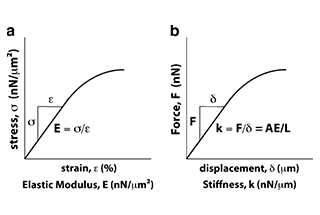
Ever wondered why some materials bend easily while others remain rigid? This blog dives into the fascinating world of elastic modulus and stiffness, unraveling their crucial roles in engineering. By…
Have you ever wondered what makes a perfect circle? In the world of mechanical engineering, roundness is a crucial concept that affects the performance and longevity of rotating components. This…
In today's fast-paced manufacturing world, efficient deburring is crucial. With numerous methods available, choosing the right one can be daunting. In this blog post, we'll explore various deburring techniques, from…
Have you ever wondered what keeps the world spinning smoothly? The unsung heroes behind the scenes are bearings. These small but mighty components play a crucial role in reducing friction…
Gears are the unsung heroes of the mechanical world, quietly working behind the scenes to keep machines running smoothly. But have you ever wondered what materials these critical components are…
This article explores the top 5 cooling tower manufacturers shaping our world. Learn how these companies innovate to keep industries running smoothly and efficiently. Get ready to uncover the secrets…
Have you ever wondered what keeps our gas systems running smoothly and safely? In this article, we explore top gas regulator manufacturers, uncovering their innovations and contributions to the industry.…
Ever wondered why connecting copper and aluminum wires is problematic? This article explains the risks associated with connecting these two metals due to their differing electrochemical properties, which can lead…