Why Does the Output Shaft Break? An In-Depth Cause Analysis
Why do output shafts break under heavy use? This crucial component often fails due to design flaws in its R-angle and oil hole chamfer. This article explores the primary causes of these fractures, including structural weaknesses and insufficient induction hardening. By understanding these failure mechanisms, you can learn how to optimize shaft design and improve the durability of mechanical systems. Dive in to discover practical solutions that enhance performance and prevent costly breakdowns.
The output shaft of the auxiliary gearbox is a crucial component that bears a significant torque during vehicle operation. Therefore, it requires high strength.
The technical requirements of the drawing include using material 40Cr and medium frequency induction hardening at R angle and spline. The hardening layer depth at R angle should be ≥ 5mm, and the hardening layer at spline should be 5-8mm from the tooth bottom. Additionally, the surface hardness should be ≥ 55HRC. The matrix should be quenched and tempered, and the hardness should be 235-265HBW.
At the beginning of 2019, the market reported that the output shaft of the auxiliary box broke frequently when customers drove between 30000-100000 km. Through analyzing the failed parts, the following reasons for the fractures were identified:
The R-angle structure of the output shaft is concave, making induction hardening difficult. This results in a shallow quenching layer and increased sensitivity to quenching cracks. Induction hardening cracks were found at the R-angle during actual detection.
The chamfer of the oil hole of the auxiliary box output shaft is 0.5mm × 45°. Due to the sharp angle effect, quenching cracking tends to be large, and quenching cracks are present.
This article provides an analysis of the causes of output shaft fractures in the auxiliary box and proposes a series of improvement measures to address the issue. The analysis is based on principles, and the measures are designed to effectively solve the problem of output shaft fractures in the auxiliary box.
1. Failure analysis
1.1 Failure detection analysis
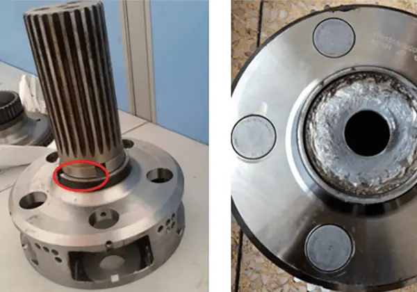
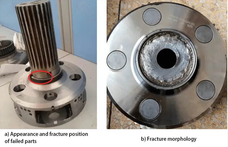
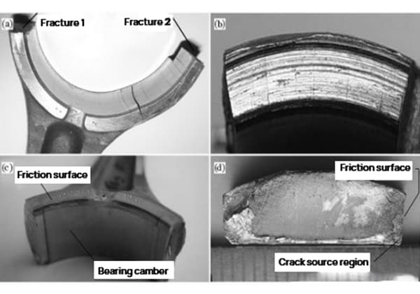
Figure 1 illustrates the failed components of the output shaft in the auxiliary box.
Specifically, Fig. 1a depicts the appearance and fracture location of the failed parts, with the red circle indicating the location of the fracture.
The fracture of the output shaft in the auxiliary box occurred at the R-angle position of the tool withdrawal groove, as evident from the figure.
Additionally, Fig. 1b displays the fracture morphology, which is characterized by a straight fracture induced by the circumferential rotation of the shaft.
Following the fracture, there are mutual wear marks at both ends, which is consistent with the torsional fracture characteristics.
Fig. 1 Failure Parts of Output Shaft of Auxiliary Box
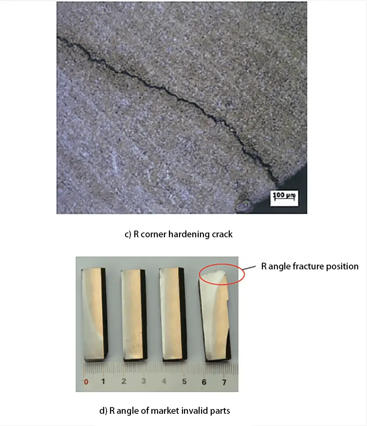
Non-destructive testing and metallographic analysis were conducted on both the finished products and the failure parts that were returned from the market, and the test results are presented in Table 1.
As can be seen from the table, the induction quenching results of the spline parts in both the finished products and market failure parts meet the technical requirements. The effective hardening depth of the spline parts is ≥ 5mm, and the metallographic structure of the hardened layer is grade 4-5 acicular martensite.
However, the induction quenching results at the spline oil hole and R corner do not meet the technical requirements for the following reasons:
The finished product shows induction hardening cracks in the R-angle position and spline oil hole.
The depth of the induction hardening layer at corner R is shallow, or even non-existent, and is not more than 5mm as specified in the technical requirements.
Table 1 Magnetic Particle Testing and Metallographic Analysis Results of Finished Parts and Failure Parts
The inspection results above align with the cracking characteristics of the failed part. This is due to the fact that the induction hardening layer at the R corner of the output shaft of the auxiliary box is insufficiently deep, failing to meet the necessary technical requirements. Furthermore, an induction hardening crack has developed at the R corner, causing a low strength level at that location.
During vehicle operation, the R corner is incapable of withstanding large torsional stress and ultimately fractures. Additionally, induction hardening cracks are present at the spline oil hole, and several failed parts in the market have also experienced broken output shafts of the sub box at this location.
Fig. 2 Results of NDT and Metallographic Testing
1.2 Failure cause analysis
The failure detection results reveal two fracture risk points of the output shaft of the auxiliary box: the R-angle position and spline oil hole.
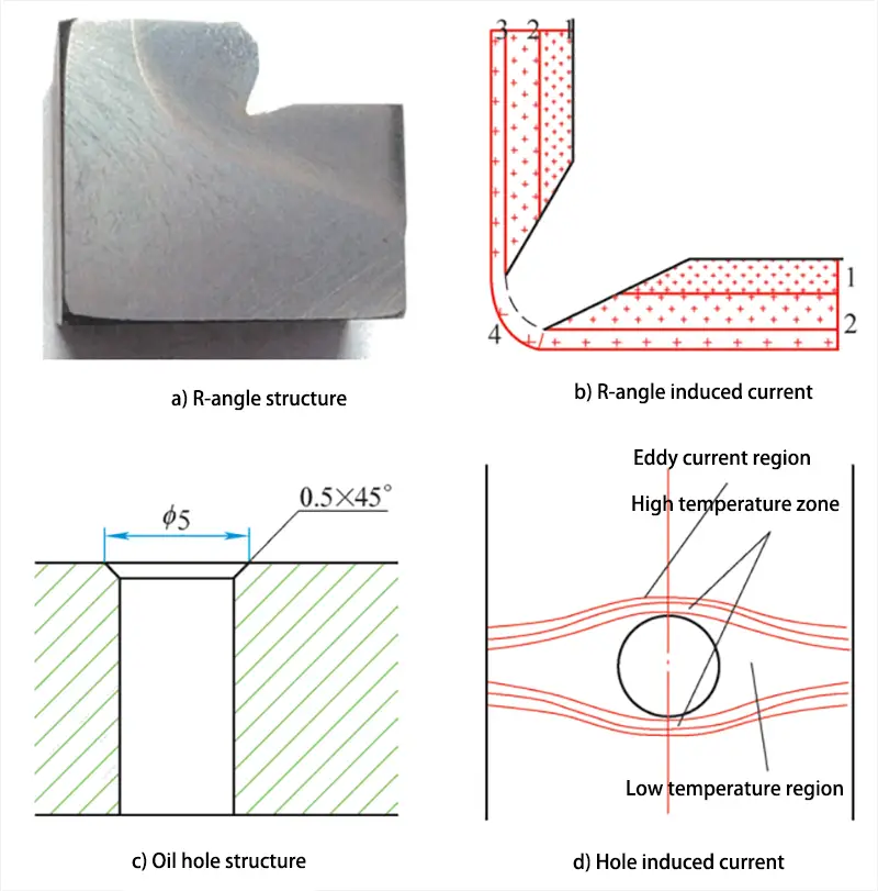
Fig. 3a illustrates the structure of the R-angle position of the finished product during production. It shows that the R-angle is an inner R0.5mm structure, which can have two effects on induction hardening.
Firstly, the transition fillet at the bottom of the R corner of the inner R type structure is too small, causing large machining stress at the bottom of the R corner depression, which increases the sensitivity of induction hardening cracks.
Secondly, the distance between the R-angle depression of the inner R type structure and the inductor is relatively large.
Figure 3b illustrates the distribution of induced current during induction heating at corner R.
As a result of the proximity effect of induction heating, the induced current decreases as the distance from the sensor increases. Thus, the induced current gradually reduces from areas 1 to 4, with the lowest induced current found in area 4, located at the bottom of the R angle, which is the farthest from the inductor.
In the same heating time, while areas 1 to 3 attain the required quenching heating temperature as a whole, area 4 may not achieve complete quenching temperature. Consequently, water spray cooling takes place, causing martensite transformation in areas 1 to 3, but only partial martensite transformation or no transformation in area 4.
This inconsistency in the hardened layer depth of regions 1 to 3 and region 4 leads to uneven deformation due to structural transformation inside and outside the R angle. Furthermore, region 4 experiences tensile stress due to structural transformation, making it susceptible to machining stress concentration, ultimately resulting in quenching cracks during quenching.
Moreover, since area 4 is the farthest from the inductor, it is the most challenging part for induction hardening, and the depth of hardening layer in this area is insufficient.
Figure 3c illustrates the chamfered structure of the oil hole in the output shaft of the currently produced auxiliary tank. The design size of the oil hole is 0.5mm × 45°, which does not comply with the requirements for induction hardening of hole chamfers.
To ensure the quality of induction hardening, a slightly greater chamfer of more than 1mm × 45° is necessary. This is because a small chamfer results in high temperatures around the oil hole due to the sharp angle effect of induction heating, leading to the formation of quenching cracks.
Furthermore, the presence of the oil hole forces the induced current to bypass on both sides of the hole, resulting in uneven eddy current density around the hole. The eddy current density on both sides of the hole along the current direction is high, while the density on both sides perpendicular to the current direction is low. This creates a high-temperature area on one side and a low-temperature area on the other, as shown in Figure 3d.
Due to this uneven heating, the depth of current penetration and the thickness of the hardened layer after quenching are different. The generation of organizational and thermal stress during induction quenching is the fundamental cause of quenching cracks at the edge of the oil hole. Additionally, the cooling of the edge of the oil hole is more intense than that of other areas during cooling, making it more susceptible to the formation of quenching cracks.
Fig. 3 R angle and oil hole
2. Improvement measures
2.1 Structural optimization of R angle and oil hole chamfer
Based on the above analysis, it is evident that the fracture of the output shaft of the auxiliary box is due to the flawed design of the R angle structure and the oil hole chamfer.
Consequently, the following corrective measures have been developed:
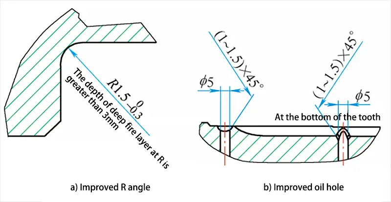
The transition fillet structure has been modified to R1.5mm, and the depth of the induction hardening layer at the optimized fillet is required to be ≥ 3mm.
The oil hole chamfer structure has been improved to (1~1.5) mm × 45°.
Figure 4a displays the optimized structure for the R angle.
During the induction heat treatment process, if the step root of the workpiece requires induction hardening, a transition fillet must be incorporated. The larger the fillet, the better the outcome.
This design offers good processability:
① It reduces stress concentration at the root of the step and minimizes the tendency for cracking during use.
② It reduces the difficulty of induction quenching, ensures uniform heating of the step root, enables a uniform and continuous hardening layer on the step, and significantly enhances strength.
Figure 4b illustrates the optimized design for the oil hole chamfer, with an increased chamfer size of (1~1.5) mm × 45 °. Under the same heating conditions, the larger the oil hole chamfer, the higher the current density at the edge of the oil hole, and the lower the probability of the oil hole edge cracking due to overheating.
Fig. 4 structural optimization
2.2 Induction hardening process optimization
The scanning quenching method is used to complete the quenching of the auxiliary box’s output shaft due to the large quenching area and small power supply. The significant advantage of scanning quenching is that it can use equipment with smaller capacity to handle large workpieces.
To perform scanning quenching, the workpiece is placed in or near the inductor, allowing the inductor and workpiece to move relative to each other. The inductor connects high-frequency or medium-frequency current to inductively heat the workpiece to the quenching temperature. Simultaneously, the inductor or water jet sprays quenching cooling medium onto the workpiece’s part that has reached the quenching temperature.
The quenching process continues until the entire quenching area of the workpiece is treated. To stop the process, the inductor current is cut off first, followed by the injection of quenching cooling medium.
Figure 5 illustrates the optimized design of the inductor’s effective circle. This structure consists of a whole circle that rotates at a specific angle (usually 45°) to ensure proper heating of the plane and the R angle at the variable section. The effective ring is equipped with a “Π,” and the magnetic conductor’s slot is inclined towards the R angle area.
By leveraging the slot effect of the magnetic conductor, the medium frequency current of the effective coil is expelled to the R angle area, thereby strengthening the heating of the R angle region. To ensure rapid heating of the R angle, there is a 3-5 mm gap between the front end of the effective coil and the R angle. This arrangement enables the quenching temperature to be reached within 10 seconds, leading to an ideal hardening layer distribution.
However, when heating the R angle, the inductor must remain in this area for a specific period to obtain sufficient hardening layer depth at the R angle. During this time, the adjacent splines above the R angle are also being heated. To prevent the hardening layer depth of these splines from being too deep, which could result in “bulging” of the hardening layer at the transition between the R angle and the axial spline, the proximity effect of induction heating is used.
Specifically, when designing the inductor, the surface of the heating spline and the spline axis form an included angle of 7.5° to minimize the proximity effect. As we move closer to the R angle region, the spacing decreases, leading to a black shadow in Figure 5, which indicates the induced current distribution in the R angle area and its adjacent regions.
Finally, when heating the R corner area, the inductor moves upward to heat and quench the spline area, resulting in a uniform and continuous hardening layer that improves the overall strength of the output shaft.
Fig. 5 Design of effective circle
3. Conclusion
After analyzing the causes of the output shaft fracture in the auxiliary box, three improvement measures were identified:
Optimization of the transition fillet structure: The structure of the transition fillet will be improved to r1.5mm for the outer fillet, and the technical requirement of the induction hardening layer depth at the fillet will be set to ≥ 3mm.
Optimization of the oil hole chamfer size: The chamfer structure of the oil hole will be improved to (1 ~ 1.5) mm × 45°.
Optimization of the inductor’s effective ring structure: The scanning induction hardening method will be adopted to make the hardening layer of the fillet and spline continuous and uniform.
After implementing these measures, the output shaft of the auxiliary box was inspected and monitored, and significant improvements were observed:
The R-angle strength of the output shaft of the sub-tank has been significantly improved, and there are no longer any induction hardening cracks in the oil hole chamfer and the R-angle area.
The fillet and hardening layer of the output shaft are now continuous and uniform. The hardening layer at the R-angle is 4 ~ 6mm deep, while the hardening layer at the spline part is 5 ~ 8mm deep. The metallographic structure of the hardening layer is 4 ~ 6 grade acicular martensite, and the surface hardness is 56 ~ 59HRC, meeting the technical requirements.
The output shaft of the sub-box has not cracked after delivery and loading, significantly reducing the risk of market claims and improving product quality and customer satisfaction.
As the founder of MachineMFG, I have dedicated over a decade of my career to the metalworking industry. My extensive experience has allowed me to become an expert in the fields of sheet metal fabrication, machining, mechanical engineering, and machine tools for metals. I am constantly thinking, reading, and writing about these subjects, constantly striving to stay at the forefront of my field. Let my knowledge and expertise be an asset to your business.
Have you ever struggled with the precise installation of synchronous belt pulleys and shafts? This article provides clear, step-by-step methods to ensure accurate and secure assembly. You'll discover common installation…
Have you ever wondered how power is transmitted in various machines and devices? From the engines that propel our vehicles to the motors that drive our industries, power transmission is…
Have you ever wondered how machines convert invisible forces into powerful movements? In this blog post, we'll explore the fascinating worlds of pneumatic and hydraulic transmissions. You'll learn how these…
Have you ever wondered why metal parts suddenly break without warning? This article explores the fascinating world of metal fatigue and fracture. You'll learn how repeated stress can lead to…
Imagine your car's engine suddenly stops working, leaving you stranded. The culprit? A malfunctioning gearbox. This comprehensive guide to gearbox operation explores everything from installation and safety precautions to maintenance…
Ever wondered why your metal parts aren't as smooth as you'd like? Burrs, those tiny metal fragments, might be the culprit. In this article, we'll explore what burrs are, their…
Have you ever wondered how excavators and other heavy machinery perform their powerful tasks? In this article, we’ll explore the fascinating differences between hydraulic pumps and motors. You'll learn how…
Have you ever wondered how machines precisely know their position and speed? This article explores the fascinating world of encoders, sensors crucial for detecting mechanical motion. You'll learn about different…
Ever wondered how machines achieve precise movements? This blog dives into the fascinating world of servo motor control modes. From pulse to analog control, we'll explore how each method works…