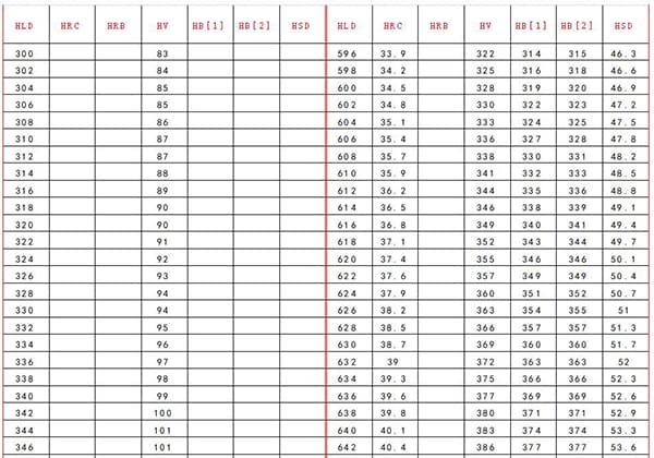
Hardness Conversion Chart: HLD, HRC, HRB, HV, HB, HSD
Have you ever wondered what those mysterious numbers on a metal part mean? In this blog post, we'll dive into the fascinating world of hardness testing and explore the different…
Ever wondered why diamonds are so hard? In this article, we’ll explore the fascinating world of material hardness, from talc to diamond. You’ll learn how different tests, like Brinell, Rockwell, and Vickers, measure this crucial property, and why it matters in engineering. Get ready to uncover the secrets behind the strength of materials!
Hardness: the ability to resist local indentation deformation or scratch fracture.
Two kinds of Mohs hardness sequence tables
| Order | Material | Order | Material |
| 1 | talc | 1 | talc |
| 2 | gupse | 2 | gupse |
| 3 | calcite | 3 | calcite |
| 4 | fluorite | 4 | fluorite |
| 5 | apatite | 5 | apatite |
| 6 | orthoclase | 6 | orthoclase |
| 7 | quartz | 7 | SiO2 glass |
| 8 | topaz | 8 | quartz |
| 9 | corindon | 9 | topaz |
| 10 | adamas | 10 | garnet |
| – | 11 | Fused zirconia | |
| – | 12 | corindon | |
| – | 13 | silicon carbide | |
| – | 14 | Carbonization shed | |
| – | 15 | diamond | |
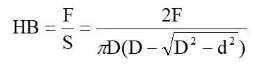
To determine the Brinell hardness of a metal material, apply a certain load F with a spherical indenter of diameter D onto its surface and maintain it for a specific duration. This process will result in the formation of a spherical indentation, and the load value per unit area of the indentation is considered as the Brinell hardness of the metal material.
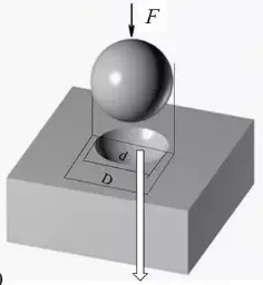
Measuring indentation diameter
Indenter material:
For example: 280HBS10/3000/30
1kgf=9.81N
General conditions: 10mm steel ball diameter; 3000kg load; 10s pressure holding time, namely HB280

When measuring Brinell hardness with indenters of different diameters and loads of different sizes, the principle of geometric similarity must be met to obtain the same HB value, that is, the opening angleφ of the indentation is equal.
Method: The same HB shall be measured for samples with the same material but different thickness, or materials with different hardness and softness.
When selecting D and F, F/D2 shall be the same.
Principle of geometrical similarity of indentation:![]()
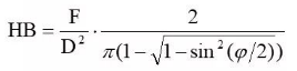
It can be seen that as long as F/D remains constant, HB only depends on the pressing angle φ.
F/D2 ratio: 30,15,10,5,2.5,1.25,1
According to the engineering regulations, the ratio of F/D2 is 30, 10 and 2.5, which are selected according to the material hardness and sample thickness.
See various standards and test specifications for details.
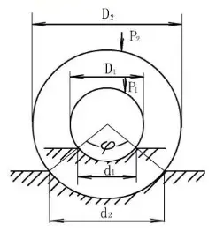
Fig. 1-21 Application of similarity principle
Selection Table of Brinell Hardness Test P/D2
| Material type | Brinell hardness number/HB | Sample thickness/mm | Relationship between load P and indenter diameter D | Diameter of indenter D/nm | Load P/kgf | Load holding time/s |
| Ferrous metal | 140~450 | 6~3 4-2 <2 | P=30D2 | 1052.5 | 3000 750 187.5 | 10 |
| <140 | >6 6~3 <3 | P=10D2 | 1052.5 | 1000 250 62.5 | 10 | |
| Nonferrous metals | >130 | 6~3 4-2 <2 | P=30D2 | 1052.5 | 3000 750 187.5 | 30 |
| 36~130 | 9~3 6~2 <3 | P=10D2 | 1052.5 | 1000 250 62.5 | 30 | |
| 8-35 | >6 6~3 <3 | P=2.5D2 | 1052.5 | 250 62.5 15.6 | 60 |
The experiment shows that HB is stable and comparable when 0.25D<d<0.5D.
If it has influence on the test, it shall be carried out in strict accordance with the regulations, generally 10s and 30s.
This method is well-suited for coarse or heterogeneous materials due to its large indentation area and high measurement accuracy. However, due to the large indentation size, inspection of finished products can be challenging.
It is primarily utilized for inspecting raw materials, and the indenter material is limited to softer materials (HB450~650). Additionally, the efficiency of indentation measurement is relatively low.
Indentation depth can be used to reflect the hardness of materials.
To adapt to different soft and hard materials, many grades of hardness testers use different indenters and loads.
One common grade is C, HRC, which uses a 150kgf total load and a 120° diamond cone indenter that is loaded twice.
First, an initial load of P1=10kgf is applied to ensure proper contact between the indenter and the material surface. Then, the main load of P2=140kgf is added.
After removing P2, the depth of the indentation is measured and used to determine the hardness of the material.
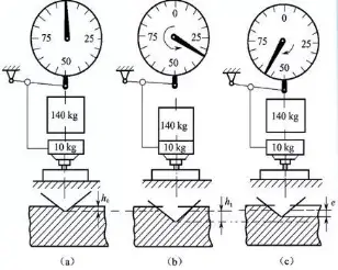
Fig. 3-17 Schematic Diagram of the Principle and Test Process of Rockwell Hardness Test
(a) Add preload (b) Add main load (c) Unload main load
| Hardness symbol | Head used | Total test force N | Scope of application | Applied range |
| HRA | Diamond cone | 588.4 | 20-88 | Carbide, hard alloy, quenched tool steel, shallow case hardening steel |
| HRB | φ 1.588mm steel ball | 980.7 | 20-100 | Mild steel, copper alloy, aluminum alloy, malleable cast iron |
| HRC | Diamond cone | 1471 | 20-70 | Quenched steel, quenched and tempered steel, deep case hardened steel |
Indenter: 120 diamond cone or hardened steel ball
Rockwell hardness definition:
0.002mm residual indentation depth is a Rockwell hardness unit.
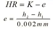
K – constant, 130 for steel ball indenter and 100 for diamond indenter
Table 3-6 Test Specification and Application of Rockwell Hardness
| Ruler | Type of indenter | Initial test force/N | Main test force/N | Total test force/N | Constant K | Hardness range | application examples |
| A | Diamond circular dimension | 100 | 500 | 600 | 100 | 60~85 | High hardness thin parts and cemented carbides |
| B | φ1.588mm steel ball | 900 | 1000 | 130 | 25~100 | Non ferrous metals, malleable cast iron and other materials | |
| C | Diamond circular dimension | 1400 | 1500 | 100 | 20~67 | Heat treated structural steel and tool steel | |
| D | Diamond cone | 900 | 1000 | 100 | 40-77 | Surface hardened steel | |
| E | φ3.175mm steel ball | 900 | 1000 | 130 | 70~100 | Plastic | |
| F | φ1.588mmm steel ball | 500 | 600 | 130 | 40~100 | Non ferrous metals | |
| G | φ1.588mm steel ball | 1400 | 1500 | 130 | 31~94 | Pearlitic steel, copper, nickel, zinc alloy | |
| H | φ3.175mm steel ball | 500 | 600 | 130 | – | Annealed copper alloy | |
| K | φ3.175mm steel ball | 1400 | 1500 | 130 | 40~100 | Non ferrous metals and plasticsSoft metal and non-metallic soft materialsHigh hardness thin parts and cemented carbidesNon ferrous metals, malleable cast iron and other materials | |
| L | φ6.350mm steel ball | 500 | 600 | 130 | – | ||
| M | φ6.350mm steel ball | 900 | 1000 | 130 | – | ||
| P | φ6.350mm steel ball | 1400 | 1500 | 130 | – | ||
| R | φ12.70mm steel ball | 500 | 600 | 130 | – | Heat treated structural steel and tool steel | |
| S | φ12.70mm steel ball | 900 | 1000 | 130 | – | ||
| V | φ12.70mm steel ball | 1400 | 1500 | 130 | – |
Characteristics and Application of Rockwell Hardness
(1) This method allows for direct reading of the hardness value and is highly efficient, making it suitable for batch inspection.
(2) The indentation is small and generally considered “nondestructive,” making it suitable for inspecting finished products.
(3) However, the small indentation size can result in poor representativeness and therefore is not suitable for coarse or non-uniform materials.
(4) The Rockwell hardness test is divided into various scales, each with a wide range of applications.
(5) It is important to note that Rockwell hardness values obtained from different scales are not comparable.
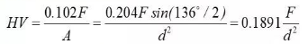
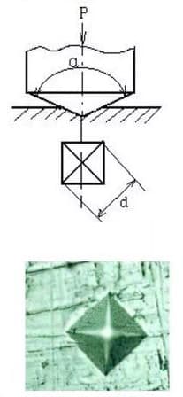
Press a diamond pyramid into the metal surface with a certain load F to form a pyramid indentation.
The load value on the unit indentation area is the Vickers hardness of the metal material.
When the unit of test force F is kgf:
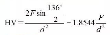
When the unit of test force F is N:
Indenter material: diamond pyramid with an included angle of 136 °
For example: 270HV30/20, if the holding time is 10-15s, it can be recorded as 270HV
Vickers hardness with very small load, the load is 5-200gf.
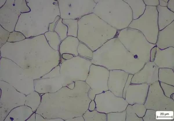
Indicated by Hm, it can be used to test the hardness of single grain or phase.
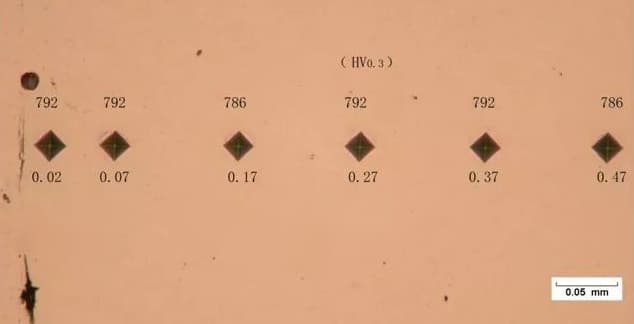
| Vickers hardness test | Low load Vickers test | Micro Vickers hardness test | |||
| Hardness symbol | Test force/N | Hardness symbol | Test force/N | Hardness symbol | Test force/N |
| HV5 | 49.03 | HVO.2 | 1.961 | HVO.01 | 0.09807 |
| HV10 | 98.07 | HVO.3 | 2.942 | HVO.015 | 0.1471 |
| HV20 | 196.1 | HVO.5 | 4.903 | HVO.02 | 0.1961 |
| HV30 | 294.2 | HV1 | 9.807 | HVO.025 | 0.2452 |
| HV50 | 490.3 | HV2 | 19.61 | HVO.05 | 0.4903 |
| HV100 | 980.7 | HV3 | 29.42 | HVO.1 | 0.9807 |
| Note: 1. The Vickers hardness test can use a test force greater than 980.7N;2. The micro Vickers test force is recommended. | |||||
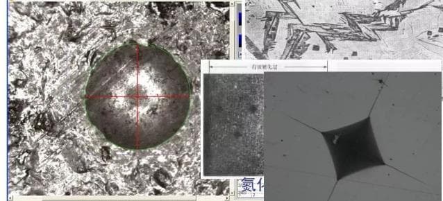
Characteristics and Application of Vickers Hardness
(1) The geometrical shape of the indentation is always similar, while the load can be varied.
(2) The corner cone indentation contour is distinct, resulting in high measurement accuracy.
(3) The diamond indenter has a broad range of applications and can provide consistent hardness scales for various materials.
(4) The efficiency of indentation measurement is low, making it unsuitable for on-site batch inspection.
(5) The indentation is small and not appropriate for coarse or heterogeneous materials.
However, metallographic specimens can be used to measure the hardness or hardness distribution of various phases.
① The stress state is very soft (α>2), which is widely applicable;
Hardness of some materials
| Material | Condition | Hardness/(kgf/mm ²) | |
| Metallic Materials | 99.5% aluminum | annealing | 20 |
| cold rolling | 40 | ||
| Aluminum alloy (A-Zn Mg Cu)Mild steel (tc=0.2%) | annealing | 60 | |
| Precipitation hardening | 170 | ||
| Bearing steelAluminum alloy (A-Zn Mg Cu) | normalizing | 120 | |
| cold rolling | 200 | ||
| Mild steel (tc=0.2%) | normalizing | 200 | |
| Quenching (830 ℃) | 900 | ||
| Tempering (150 ℃) | 750 | ||
| ceramic materials | WC | agglutination | 1500~2400 |
| Cermet (Co=6%, allowance WC) | 20℃ | 1500 | |
| 750℃ | 1000 | ||
| Al2O3 | ~1500 | ||
| B4C | 2500~3700 | ||
| Material | Condition | Hardness/(kgf/mm²) |
| BN (cubic meter) | 7500 | |
| diamond | 6000-10000 | |
| Glass | ||
| Silica | 700-750 | |
| Soda lime glass | 540~580 | |
| optical glass | 550-600 | |
| Polymer | ||
| High pressure polyethylene | 40-70 | |
| Phenolic plastic (filler) | 30 | |
| polystyrene | 17 | |
| organic glass | 16 | |
| polyvinyl chloride | 14~17 | |
| ABS | 8-10 | |
| polycarbonate | 9-10 | |
| Polyoxymethylene | 10~11 | |
| Polytetraethylene oxide | 10~13 | |
| polysulfone | 10~13 |
Covalent bond ≥ ionic bond>metal bond>hydrogen bond>Van’s bond
② The method is simple, nondestructive and suitable for field inspection;
③ The physical meaning is not clear, and it is difficult to design quantitatively.
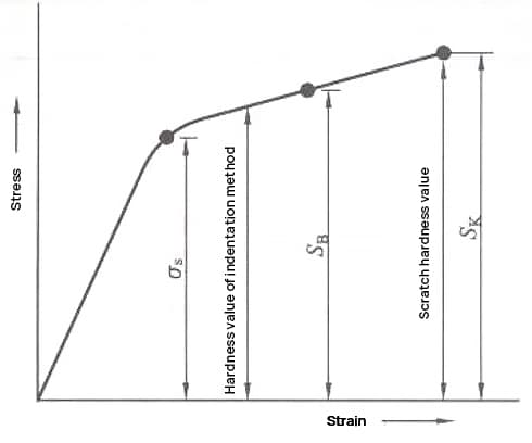
σb≈KH
Steel: K=0.33~0.36
Copper alloy, stainless steel, etc.: K=0.4~0.55
Relationship between hardness and strength of annealed metals
| Name of metal and alloy | HB | σb/MPa | k(σb/HB) | σ-1/MPa | σ(σ-1/HB) | |
| Non ferrous metalsFerrous metalNon ferrous metals | Copper | 47 | 220.30 | 4.68 | 68.40 | 1.45 |
| Aluminium alloy | 138 | 455.70 | 3.30 | 162.68 | 1.18 | |
| Duralumin | 116 | 454.23 | 3.91 | 144.45 | 1.24 | |
| Ferrous metal | Industrial pure iron | 87 | 300.76 | 3.45 | 159.54 | 1.83 |
| 20 steel | 141 | 478.53 | 3.39 | 212.66 | 1.50 | |
| 45 steel | 182 | 637.98 | 3.50 | 278.02 | 1.52 | |
| 18 Steel | 211 | 753.42 | 3.57 | 264.30 | 1.25 | |
| T12 steel | 224 | 792.91 | 3.53 | 338.78 | 1.51 | |
| 1Cr18Ni9 | 175 | 902.28 | 5.15 | 364.56 | 2.08 | |
| 2Cr13 | 194 | 660.81 | 3.40 | 318.99 | 1.64 | |
Note: Unit of hardness!
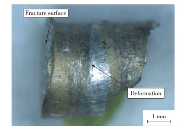
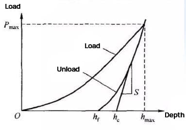
During the loading process, elastic deformation first occurs on the surface of the specimen. As the load increases, plastic deformation gradually appears and also increases.
The unloading process is primarily the recovery of elastic deformation, while the plastic deformation ultimately causes an indentation to form on the sample surface.
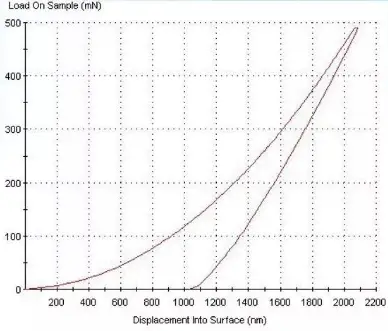
Load displacement curve of nano indentation
Principle of nano indentation test
There are important differences between nano hardness and traditional hardness:
First of all, the two definitions are different.
Nanohardness: the instantaneous force borne by a unit area on the projection of the surface area of the base indentation during the indentation process of the sample, which is a measure of the sample’s ability to withstand the contact load;
Vickers hardness is defined as the average force per unit area on the surface area of the indentation retained after the unloading of the indenter, which reflects the ability of the specimen to resist linear residual deformation.
In the process of measuring hardness, if plastic deformation dominates the process, the results of the two definitions are similar. However, if the process is dominated by elastic deformation, the results will differ.
In pure elastic contact, the residual contact area is very small. Therefore, the traditional definition of hardness will yield an infinite value, making it impossible to obtain the true hardness value of the sample.
Furthermore, the measurement ranges of the two methods are different. Traditional hardness measurement is only applicable to large-sized samples, not only due to limitations of the measuring instrument, but also because the residual indentation cannot accurately reflect the true hardness of the sample at the micro- and nano-scales.
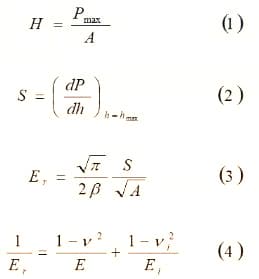
New measurement techniques and calculation methods are used for nano hardness measurement, which can more accurately reflect the hardness characteristics of the sample at the micro- and nano-scales.
The key difference between the two methods is the calculation of indentation area. Nano hardness measurement involves measuring the indentation depth and then calculating the contact area using an empirical formula, whereas traditional hardness measurement involves obtaining the surface area of the indentation from photos taken after unloading.
The basic components of a nano hardness tester can be divided into several parts, including the control system, moving coil system, loading system, and indenter.
Diamond indenters, which are typically triangular cones or four-edge dimensions, are commonly used.
During the test, initial parameters are inputted first, and the subsequent detection process is fully automated by the microcomputer.
Manipulation of the loading system and the action of the indenter can be achieved by changing the current in the moving coil system.
Measurement and control of the indenter pressing load are carried out by the strain gauge, which also provides feedback to the moving coil system for closed-loop control, enabling completion of the test according to the input parameter settings.

As the founder of MachineMFG, I have dedicated over a decade of my career to the metalworking industry. My extensive experience has allowed me to become an expert in the fields of sheet metal fabrication, machining, mechanical engineering, and machine tools for metals. I am constantly thinking, reading, and writing about these subjects, constantly striving to stay at the forefront of my field. Let my knowledge and expertise be an asset to your business.