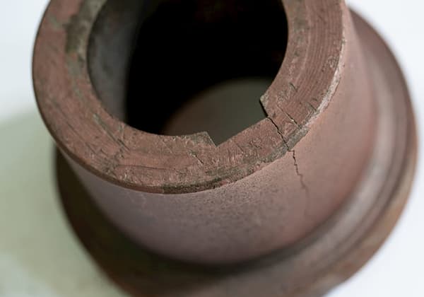
1. What is fatigue?
Fatigue refers to the decline in the structural performance of materials, particularly metals, when subjected to cyclic stress or strain, ultimately leading to failure.
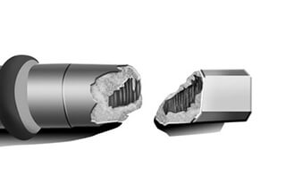
Fatigue failure is a prevalent form of failure.
Research shows that fatigue failures account for 60 to 70% of failures in various machinery.
Fatigue fracture failure is classified as low-stress brittle fracture failure, and it is challenging to detect significant plastic deformation during fatigue, as it primarily results from local plastic deformation and occurs at structural weaknesses.
While frequency can play a role in fatigue failure, it is typically linked to the number of cycles rather than frequency.
According to the characteristics of stress that cause fatigue failure, it can be divided into two categories:
- Mechanical fatigue caused by mechanical stress, and
- Thermal fatigue caused by alternating thermal stress.
Regarding cycle times, fatigue can be further divided into:
- High cycle,
- Low cycle, and
- Ultra-high cycle fatigue.
In terms of load properties, fatigue can be classified into:
- Tension-compression fatigue,
- Torsion fatigue, and
- Bending fatigue.
And based on the working environment of the workpiece, fatigue can be divided into:
- Corrosion fatigue,
- Low temperature fatigue, and
- High temperature fatigue.
It’s worth noting that the strength of materials and structures before fatigue damage is referred to as the “fatigue limit.
2. Types of fatigue
1. Impact fatigue
It refers to fatigue caused by repeated impact loads.
When the number of impacts, N, is less than 500 to 1000, the parts can become damaged and the fracture form of the parts will be similar to that of a single impact.
When the number of impacts exceeds 105, the part fracture is classified as a fatigue fracture, exhibiting typical fatigue fracture characteristics.
In the design calculation, if the number of impacts exceeds 100, the strength should be calculated using a method similar to fatigue analysis.
2. Contact fatigue
Under the influence of cyclic contact stress, parts will experience gradual and permanent damage at the local level.
After a certain number of cycles, the development of pitting, shallow peeling, or deep peeling on the contact surface is referred to as contact fatigue.
Contact fatigue is a common mode of failure for gears, rolling bearings, and camshafts.
3. Thermal fatigue
Materials or parts that experience fatigue due to cyclic thermal stress caused by temperature changes are referred to as thermal fatigue.
Cyclic changes in temperature result in cyclic changes in the volume of the material.
When the material’s ability to expand or contract freely is restricted, cyclic thermal stress or cyclic thermal strain is generated.
There are mainly two kinds of thermal stress:
The thermal expansion and contraction of parts are affected by the constraints of fixed parts, leading to thermal stress.
In absence of external constraints, inconsistent temperatures among parts of two pieces result in uneven thermal expansion and contraction, resulting in thermal stress.
Temperature fluctuations also cause changes in the internal structure of the material, reducing its strength and plasticity.
Under thermal fatigue conditions, the temperature distribution is not uniform, leading to serious plastic deformation, large temperature gradients, and thermal strain concentrations.
When the thermal strain exceeds the elastic limit, the relationship between thermal stress and thermal strain is no longer linear and must be treated as an elastoplastic relationship.
Thermal fatigue cracks start from the surface and extend inward, perpendicular to the surface.
The thermal stress is proportional to the thermal expansion coefficient, with larger coefficients leading to greater thermal stress.
Therefore, material selection should consider matching of materials, with differences in thermal expansion coefficients not being too large.
Under the same thermal strain conditions, the greater the elastic modulus of the material, the higher the thermal stress.
The greater the temperature cycle change, i.e., the difference between upper and lower limit temperatures, the higher the thermal stress.
The lower the thermal conductivity of the material, the steeper the temperature gradient and the greater the thermal stress during rapid acceleration or cooling.
4. Corrosion fatigue
The fatigue caused by the joint action of a corrosion medium and cyclic stress is referred to as corrosion fatigue.
Damage caused by the combined action of a corrosion medium and static stress is referred to as stress corrosion.
The key difference between the two is that stress corrosion only occurs in specific corrosion environments, while corrosion fatigue can occur in any corrosion environment under the influence of cyclic stress.
For stress corrosion cracking, there is a critical stress intensity factor known as KISCC. If the stress intensity factor KI is less than or equal to KISCC, stress corrosion cracking will not occur. However, there is no critical stress intensity factor for corrosion fatigue and fracture will occur as long as there is cyclic stress in a corrosion environment.
The difference between corrosion fatigue and fatigue in air is that, except for stainless steel and nitrided steel, the surfaces of mechanical parts subjected to corrosion fatigue become discolored. Additionally, corrosion fatigue results in a large number of cracks, as opposed to just one. The S-N curve for corrosion fatigue does not have a horizontal portion.
It is important to note that the corrosion fatigue limit is only conditional and is based on a certain life. The factors affecting corrosion fatigue strength are more complex than those affecting fatigue in air. For example, while the fatigue test frequency has no effect on the fatigue limit in air when it is less than 1000 Hz, it has an impact on corrosion fatigue over the entire frequency range.
3. Fatigue life
When a material or mechanical component fails, the total life usually consists of three parts:
1. Crack initiation life
A significant number of engineering studies have demonstrated that the crack initiation life of mechanical components accounts for a large portion, even up to 90%, of the total fatigue life during actual service.
2. Stable crack growth life
In most cases, when the depth of a microcrack reaches approximately 0.1mm, it will continuously grow along the portion of the material or component.
3. Instability extends to fracture life
4. Fatigue form of metal materials
Fatigue of metal materials mainly includes the following:
- General Plastic Deformation;
- Low-Cycle Fatigue Plastic Deformation;
- High-Cycle Fatigue Plastic Deformation;
- Ultra-High-Cycle Fatigue Micro Plastic Deformation of Crystal Size.
5. Factors affecting the fatigue strength of materials and structures
1. Average stress
With the rise in average stress (statistical stress), the dynamic anti-fatigue stress of materials decreases.
For forces with equal characteristics, the greater the average stress σm, the lower the stress amplitude σa for a given lifespan.
2. Stress concentration
Due to the demands of working conditions or processing techniques, components often have features such as steps, tiny holes, keyways, etc. These features cause abrupt changes in the cross-section, leading to local stress concentration, which significantly decreases the fatigue limit of the material.
Experiments have shown that the reduction in the fatigue limit is not directly proportional to the stress concentration factor.
To accurately predict the fatigue performance of mechanical components, it is necessary to estimate the crack initiation life of high stress regions or manufacturing defects.
3. Residual stress
The literature review highlights that it is relevant to only consider the impact of residual stress on metal fatigue strength under high cycle fatigue. This is because residual stress relaxes greatly under the high strain amplitude of low cycle fatigue, and therefore has little effect on low cycle fatigue.
Surface residual compressive stress is advantageous for components subjected to axial load and when the fatigue crack originates from the surface. However, it is important to be aware of the problem of residual stress relaxation caused by the yield of residual tensile stress in the core region after external load is applied.
The effect of residual stress on the notch fatigue strength of components is highly significant. This is because residual stress contains stress concentration and has a greater impact on fatigue crack growth.
However, the stress concentration of residual stress is not only linked to notch geometry, but also to material properties.
4. Size effect
The fatigue limit value of a material, denoted as σ-1, is usually determined using a small sample, with a diameter that typically ranges from 7 to 12 mm. However, the cross-section of actual components is often larger than this size.
Tests have shown that the fatigue limit decreases as the specimen diameter increases.
In particular, the fatigue limit drops more rapidly for high-strength steel than for low-strength steel.
5. Member surface state
The surface of a component is prone to producing a fatigue crack, and the surface stress of a component under alternating bending or alternating torsional load is the greatest.
The roughness of the component surface and the presence of machining tool marks can affect its fatigue strength.
Surface damage, such as tool marks or wear marks, acts as a surface notch, causing stress concentration and reducing the fatigue limit.
The higher the material strength, the more sensitive it is to notches, and the greater the effect of machined surface quality on the fatigue limit.
6. Environmental factors
The fatigue behavior of metal materials is influenced by the surrounding liquid or gas environment. Corrosion fatigue” refers to the response of metal materials to the combined effect of a corrosive medium and cyclic loads, typically in an aqueous environment.
Different environmental conditions, such as corrosion fatigue, low temperature fatigue, high temperature fatigue, and varying air pressure and humidity, can all affect the fatigue behavior of materials. In atmospheric environments, the failure cycles of a material are typically fewer than in vacuum environments, and the crack initiation life in vacuum environments is longer.
When the workpiece operates close to the critical air pressure (Pcr), its fatigue life becomes highly sensitive. The fatigue life of materials in atmospheric environments, which is generally lower than in vacuum environments, decreases with rising temperature, accelerating crack growth.
The environmental humidity has a significant impact on the durability of high-strength chromium steel. Water vapor, especially at room temperature, can weaken the fracture resistance of most metals and alloys, depending on the stress level, load ratio, and other loading conditions.
There is a strong interaction between the microstructure and environment, with the gas environment affecting the fracture morphology and dislocation slip mechanism. The environment also interacts with crack closure, particularly in the near-threshold region. The impact of the environment depends on the crack surface morphology, especially in the depth direction.
At low temperatures, metal strength increases while plasticity decreases. As a result, the high cycle fatigue strength of smooth specimens is higher at low temperatures, but the low cycle fatigue strength is lower. For notched specimens, toughness and plasticity decrease even more. Low temperatures can be particularly damaging to notches and cracks, as the critical fatigue crack length at fracture decreases sharply.
“Generalized high temperature fatigue” refers to fatigue occurring at temperatures higher than normal. Although some parts may operate at temperatures higher than room temperature, high temperature fatigue is only observed when the temperature exceeds 0.5 times the melting point (Tm), or above the recrystallization temperature. At these elevated temperatures, both creep and mechanical fatigue occur, resulting in high temperature fatigue.
7. Load type
The order of fatigue limit under different loads is: rotating bending < plane bending < compression load < torsion load.
In a corrosive environment, the impact of loading frequency on crack progression is evident.
At room temperature and a testing environment, conventional frequencies (0.1-100Hz) have minimal impact on the crack growth of steel and brass.
In general, if the test loading frequency is less than 250Hz, the influence of frequency on the fatigue life of metal materials is minimal.
8. Material defects
Cracks typically originate on the surface, such as at the weld (eyelet), in cast steel (loose), or subsurface (large inclusions altering the local strain field), but are rarely found within the interior.
The initiation of cracks also depends on the number, size, type, and distribution of inclusions, as well as the direction of external forces applied.
The bond strength between inclusions and the matrix should not be overlooked.
Microcracks are the most dangerous defects in materials, with a life span of one million cycles. Microstructures control the life span of materials, with a life span of one billion cycles.
Given that the probability of defects in microsized materials is much greater than that on the material surface, the probability of crack initiation under ultra-high cycle fatigue loading in the material is naturally greater than on the surface.
Brittle materials do not undergo stress reduction or work hardening.
If there is a notch, fracture can occur under low nominal stress.
It has been observed that when there is a notch, the fatigue limit of the metal decreases, with a greater impact on the fatigue limit in materials with lower plasticity.
9. Processing method
It has been emphasized in the literature that the preparation process of fatigue test specimens is a critical factor that contributes to the variability of test results.
For example, the processes of turning, milling, straightening, and other machining methods all impact the final quality of the specimen preparation.
This is because the preparation method and heat treatment factors can affect the fatigue performance of materials, particularly heat treatment, making it difficult to achieve consistent results even with the same batch, size, and morphology of tests.
It is evident that the production and processing factors of the workpiece will cause the actual fatigue life of parts to deviate from the expected life value calculated through analysis.
10. Material Properties
The hardness of the material is a key factor in the high cycle fatigue strength (when N > 106), while toughness is an important indicator for medium and low cycle fatigue.
High-strength steel has poor toughness and therefore low fatigue performance under high stress conditions. However, it has good fatigue resistance under low stress conditions.
Low strength steel has moderate fatigue performance.
In general, the higher the elastic modulus, the slower the crack growth rate.
The effect of grain size on crack growth is only significant in extreme cases (△ K → △ Kth and △ Kmax → △ KC), and has little impact on medium-speed crack growth.
The propagation rate is related to the fracture toughness KIC (or KC).
It is widely accepted that increasing the material’s toughness will decrease the crack growth rate.
6. Discreteness of fatigue test data
The dispersion of fatigue test data can be attributed to the test equipment and the sample itself.
According to literature, a 3% error in the nominal load compared to the actual load can result in a 60% error in the fatigue life and in extreme cases, a 120% error in the life.
Although a 3% error is acceptable in fatigue testing machines, it is noted that there is no significant dispersion in static failure tests, even for materials with large strength dispersion such as casting materials and glass.
The variability in fatigue test results is influenced by material properties, including inherent material properties and the preparation process and external environment of the test. The preparation process, particularly heat treatment, is the most critical factor leading to data dispersion.
Inclusions and second-phase particles in the materials are also important contributors to data dispersion, however, the mechanism behind this is still unknown.
7. Development of structural fatigue design methods
Safe life method:
The design stress is lower than the fatigue limit, and it is considered that there is no defect in the structure.
Fail safe method:
The design stress is related to the residual strength in the event of planar defects, and this design method accommodates acceptable levels of such defects.
Safety crack method:
Certainly, the propagation of cracks that can be predicted with certainty is permitted.
Local failure method:
Ultra-high cycle fatigue test technology, which emerged in the 1990s, has demonstrated that even small micro defects such as slag inclusion, porosity, and large grains formed by forging can significantly impact the fatigue life of materials.
For steel materials, when fatigue test data is not available, an approximate S-N curve can be drawn based on the material’s tensile strength limit.
This estimation method, which associates the fatigue limit with the tensile strength and elongation at break of the specimen, is highly accurate.
In material and structure fatigue analysis, it is essential to rely on test results rather than solely on elastic-plastic calculations for accurate and reliable data.