Sheet Metal Joining Process: The Ultimate Guide
Have you ever wondered how sheet metal parts are joined together to create complex structures? In this blog post, we'll explore the fascinating world of sheet metal joining techniques. As…
Have you ever wondered about the art and science behind the sleek metal enclosures of your favorite gadgets? In this blog post, we’ll dive into the fascinating world of sheet metal fabrication. As an experienced mechanical engineer, I’ll share insights into the materials, processes, and design principles that transform flat metal sheets into the complex shapes that house our modern electronics. Get ready to explore the cutting-edge techniques and creative problem-solving that make sheet metal fabrication a critical part of product development.
Sheet metal fabrication is a comprehensive cold-working fabrication process for sheet metal (usually less than 6mm), including shearing, blanking, bending, welding, riveting, die forming and surface treatment, etc.
Its remarkable feature is that the thickness of the same part is the same.
The sheet metal fabrication process including:
Sheet metal materials are the most commonly used materials in the structural design of communication products.
Understanding the comprehensive performance of materials and the correct material selection have an important impact on product cost, product performance, product quality, and processability.
1) Use common metal materials to reduce material specifications and control as much as possible within the company’s material manual;
2) In the same product, reduce the variety of materials and sheet thickness specifications as much as possible;
3) Under the premise of ensuring the function of the parts, try to use cheap materials, reduce the consumption of materials, and reduce the cost of materials;
4) For the cabinet and some large plug boxes, it is necessary to fully consider reducing the weight of the whole machine;
5) In addition to the premise of ensuring the function of the parts, it must also be considered that the stamping performance of the material should meet the processing requirements to ensure the rationality and quality of the processing of the products.
Steel plate
1) Cold-rolled steel sheet
Cold rolled steel sheet is the abbreviation of carbon structural steel cold rolled sheet.
It is further cold-rolled from a carbon structural steel hot-rolled steel strip into a steel sheet having a thickness of less than 4 mm.
Because it is rolled at normal temperature, no iron oxide scale is produced. Therefore, the surface quality of the cold plate is good, the dimensional accuracy is high.
In addition, the annealing process makes it has better mechanical properties and process performance than hot rolled steel sheets.
Commonly used grades are low carbon steel 08F and 10# steel, which have good blanking and bending properties.
2) Continuous electroplated zinc cold rolled sheet steel
Continuous electroplated zinc cold-rolled steel sheet, ie “electrolytic sheet”.
Refers to the process of continuously depositing zinc from an aqueous solution of zinc salt into a pre-prepared steel strip to obtain a surface galvanized layer under the action of an electric field on an electro galvanizing line.
Because of the limitations of the process, the coating is thin.
3) Continuous hot-dip galvanized steel sheet
Continuous hot-dip galvanized steel sheet is referred to as galvanized sheet or tinplate.
The cold-rolled continuous hot-dip galvanized steel sheet and steel strip having a thickness of 0.25 to 2.5 mm are first subjected to a flame-heated preheating furnace to burn off surface residual oil.
At the same time, an iron oxide film is formed on the surface.
Then, it is heated to 710~920 °C in a reduction annealing furnace containing H2 and N2 mixed gases to reduce the iron oxide film to sponge iron.
After the surface activated and purified strip is cooled to a temperature slightly higher than the molten zinc, it enters the zinc pot at 450-460 °C.
The surface thickness of the zinc layer is controlled by an air knife.
Finally, adopt passivation treatment with chromate solution to improve white rust resistance.
Compared with the surface of the electro-galvanized sheet, the coating is thicker and is mainly used for sheet metal parts that require high corrosion resistance.
4) Aluminum-zinc plate
The aluminum-zinc alloy coating of the aluminum-zinc plate is composed of 55% aluminum, 43.4% zinc and 1.6% silicon at 600 ° C.
Formed a dense quaternary crystal protective layer with excellent corrosion resistance, the normal service life of up to 25 years, 3-6 times longer than a galvanized sheet and comparable to stainless steel.
The corrosion resistance of the aluminum-zinc plate is derived from the barrier function of aluminum and the sacrificial protection of zinc.
When zinc is sacrificed for trimming, scratching, and scratching of the coating, aluminum forms an insoluble oxide layer that acts as a barrier.
The above 2), 3), and 4) steel plates are collectively referred to as coated steel sheets and are widely used in communication equipment.
After the coated steel plate is processed, it can be no longer electroplated or painted.
The incision can be directly used without special treatment, and special phosphating treatment can be performed to improve the rust resistance of the incision.
From the cost analysis, the continuous electro-galvanized steel sheet is used, and the processing plant does not need to send the parts to the electroplating, which saves plating time and transportation costs.
In addition, the parts are not pickled before spraying, which improves processing efficiency.
5) Stainless steel plate
Because of its strong corrosion resistance, good electrical conductivity, high strength, etc., it is widely used.
But we should also consider its shortcomings:
Aluminum and aluminum alloy plates
The commonly used aluminum and aluminum alloy sheets are mainly composed of the following three materials:
Anti-rust aluminum 3A21, which is the old brand LF21, is an AL-Mn alloy. It is the most widely used rust-proof aluminum.
The strength of this alloy is not high (only higher than industrial pure aluminum) and cannot be heat treated and strengthened.
Therefore, the cold working method is often used to improve its mechanical properties, and it has high plasticity in the annealed state, and the plasticity is good in the semi-cold hardening.
It has low plasticity, good corrosion resistance and good weldability during cold work hardening.
Anti-rust aluminum 5A02 is the old brand LF2 series AL-Mg anti-rust aluminum.
Compared with 3A21, 5A02 has higher strength, especially high fatigue strength, high plasticity and corrosion resistance.
The heat treatment cannot be strengthened, and the weldability by contact welding and hydrogen atom welding is good, and there is a tendency for crystal cracks to form during argon arc welding, and the alloy tends to form crystal cracks during cold work hardening.
The alloy has good machinability in the cold hardening and semi-cold hardening state, and the machinability is poor in the annealed state, and it can be polished.
Hard aluminum 2A06 is the old LY6, which is a commonly used hard aluminum grade.
Hard aluminum and super-hard aluminum have higher strength and hardness than ordinary aluminum alloys, and can be used as some panel materials.
However, the plasticity is poor, and the bending cannot be performed, and the bending may cause cracks or cracks in the outer rounded portion.
There are new standards for the grade and status of aluminum alloy. The standard code of the grade representation method is GB/T16474-1996, the status code is GB/T16475-1996, and the comparison table with the old standard is shown in Table 1-1 below:
Table 1-1 Comparison table of new and old aluminum alloy grades
| Grade | States | ||||||||
| New | Old | New | Old | New | Old | New | Old | New | Old |
| 1070A | L1 | 5A06 | LF6 | 2A80 | LD8 | 2A14 | LD10 | H12 | R |
| 1060 | L2 | 5A12 | LF12 | 2A90 | LD9 | 2A50 | LD5 | O | M |
| 1050A | L3 | 8A06 | L6 | 4A11 | LD11 | 6A02 | LD2 | T4 | CZ |
| 1035 | L4 | 3A21 | LF21 | 6063 | LD31 | 7A04 | LC4 | T5 | RCS |
| 1200 | L5 | 2A02 | LY2 | 6061 | LD30 | 7A09 | LC9 | T6 | CS |
| 5A02 | LF2 | 2A06 | LY6 | 2A11 | LY11 | ||||
| 5A03 | LF3 | 2A16 | LY16 | 2A12 | LY12 | ||||
| 5A05 | LF5 | 2A70 | LD7 | 2A13 | LY13 | ||||
Copper and copper alloy plates
There are two main types of commonly used copper and copper alloy sheets, copper T2 and brass H62.
Copper T2 is the most commonly used pure copper. It has a purple appearance and is also called copper. It has high electrical and thermal conductivity, good corrosion resistance and formability.
But the strength and hardness are much lower than brass, and the price is very expensive.
It is mainly used as a corrosion element for conductive, heat conduction and consumer goods. It is generally used for parts on the power supply that need to carry large currents.
rass H62, which is a high-zinc brass, has high strength and excellent cold and hot workability and is easily used for various forms of press working and cutting.
Mainly used for various deep drawing and bending force parts, its conductivity is not as good as copper, but it has better strength and hardness, and the price is relatively moderate.
In the case of meeting the electrical conductivity requirements, brass H62 instead of copper is used as much as possible, which can greatly reduce the material cost.
For example, busbars, most of the current busbars are made of brass H62, which proved to be fully satisfactory.
There are three main types of sheet metal processing: punching & blanking, bending, and stretching.
Different processing techniques have different requirements for the sheet.
The selection of sheet metal should also be based on the general shape and processing technology of the product.
The impact of materials on blanking
Blanking requires that the sheet should be sufficiently plastic to ensure that the sheet does not crack when punched.
Soft materials (such as pure aluminum, rust-proof aluminum, brass, copper, low-carbon steel, etc.) have good punching performance, and parts with smooth cross section and small inclination can be obtained after punching;
Hard materials (such as high carbon steel, stainless steel, hard aluminum, super-hard aluminum, etc.) have poor quality after punching, and the unevenness of the section is large, especially for thick sheets.
For brittle materials, tearing is likely to occur after punching, and particularly in the case of small width, tearing is likely to occur.
The effect of materials on bending
Plates that need to be bent and formed should have sufficient plasticity and a low yield limit.
A highly plastic sheet that is less prone to cracking when bent.
Sheets with lower yield limit and lower modulus of elasticity have less springback deformation after bending, and it is easy to obtain an accurate curved shape.
Plastic materials such as low carbon steel, brass and aluminum with a carbon content of <0.2% are easily bent and formed;
More brittle materials, such as phosphor bronze (QSn6.5 ~ 2.5), spring steel (65Mn), hard aluminum, super-hard aluminum, etc., must have a large relative bending radius (r / t) when bending, otherwise cracking is prone to occur during bending.
Special attention should be paid to the choice of the hard and soft state of the material, which has a great influence on the bending properties.
For many brittle materials, the bending can cause the outer radius to crack or even break.
There are also some steel plates with higher carbon content.
If you choose a hard state, the bending will also cause cracking or even fracture of the outer radius.
These should be avoided as much as possible.
Effect of materials on drawing processing
The stretching of the sheet, especially the deep drawing, is a difficult one in the sheet metal processing process.
Not only the depth of the stretching is required to be as small as possible, the shape is as simple as possible and smooth. Besides the material is required to have good plasticity.
Otherwise, the whole part is easily deformed, partially wrinkled, or even pulled at the stretching portion.
The yield limit is low and the directional coefficient of the plate thickness is large.
The smaller the yield ratio σs/σb of the sheet, the better the punching performance and the greater the limit of the primary deformation.
When the plate thickness directivity coefficient >1, the deformation in the width direction is easier than the deformation in the thickness direction.
The larger the value of stretch radius R, the less likely it is to be thinned and fractured during the stretching process, and the better the tensile properties.
Common tensile properties are: pure aluminum sheet, 08Al, ST16, SPCD.
Material impact on stiffness
In the design of sheet metal structure, the rigidity of sheet metal structural parts is often not met.
Structural designers often use low carbon steel or stainless steel instead of low carbon steel, or replace the ordinary aluminum alloy with a hard aluminum alloy with high strength and hardness, and it is expected to increase the rigidity of the part.
There is actually no obvious effect.
For materials of the same substrate, the strength and hardness of the material can be greatly improved by heat treatment and alloying.
But the change in stiffness is small.
To improve the rigidity of the part, only by changing the material and the shape of the part can a certain effect be achieved.
See Table 1-2 for the elastic modulus and shear modulus of different materials.
Table 1-2 Elastic Modulus and Shear Modulus of Common Materials
| Elastic Modulus E | Shear Modulus G | |
|---|---|---|
| Item | GPa | GPa |
| Grey cast iron | 118~126 | 44.3 |
| Ductile iron | 173 | |
| Carbon steel, Nickel-chromium steel | 206 | 79.4 |
| Cast steel | 202 | |
| Rolled pure copper | 108 | 39.2 |
| Cold drawn pure copper | 127 | 48 |
| Rolled phosphor bronze | 113 | 41.2 |
| Cold drawn brass | 89~97 | 34.3~36.3 |
| Rolled manganese bronze | 108 | 39.2 |
| Rolled aluminum | 68 | 25.5~26.5 |
| Pull out aluminum wire | 69 | |
| Cast aluminum bronze | 103 | 11.1 |
| Cast tin bronze | 103 | |
| Hard aluminum alloy | 70 | 26.5 |
| Rolling zinc | 82 | 31.4 |
| Lead | 16 | 6.8 |
| Glass | 55 | 1.96 |
| Plexiglass | 2.35~29.4 | |
| Rubber | 0.0078 | |
| Bakelite | 1.96~2.94 | 0.69~2.06 |
| Phenolic plastic | 3.95~8.83 | |
| Celluloid | 1.71~1.89 | 0.69~0.98 |
| Nylon 1010 | 1.07 | |
| Hard tetrachloroethylene | 3.14~3.92 | |
| Polytetrachloroethylene | 1.14~1.42 | |
| Low-pressure polyethylene | 0.54~0.75 | |
| High-pressure polyethylene | 0.147~0.24 | |
| Concrete | 13.73~39.2 | 4.9~15.69 |
Performance comparison of commonly used plates
Table 1-3 Comparison of performance of several commonly used plates
| Price coefficient | Lap resistance (mΩ) | CNC punching processing performance | Laser processing performance | Bending performance | Rivet nut technology | Pressing rivet technology | Surface coating | Incision protective performance |
|---|---|---|---|---|---|---|---|---|
| 1 | good | good | good | good | good | Average | Very good | |
| 1.2 | 27 | good | good | good | good | good | Average | good |
| 1.7 | 26 | good | good | good | good | good | Average | poorest |
| 1.3 | 26 | good | good | good | good | good | Average | relatively poor |
| 1.4 | 23 | good | good | good | good | good | Average | poor |
| 6.5 | 60 | poor | good | average | poor | very poor | poor | good |
| 2.9 | 46 | Average | extreme poor | good | good | good | Average | good |
| 3 | 46 | Average | extreme poor | extreme poor | good | good | Average | good |
| 5.6 | good | extreme poor | good | good | good | Average | good | |
| 5 | good | extreme poor | good | good | good | Average | good |
Note:
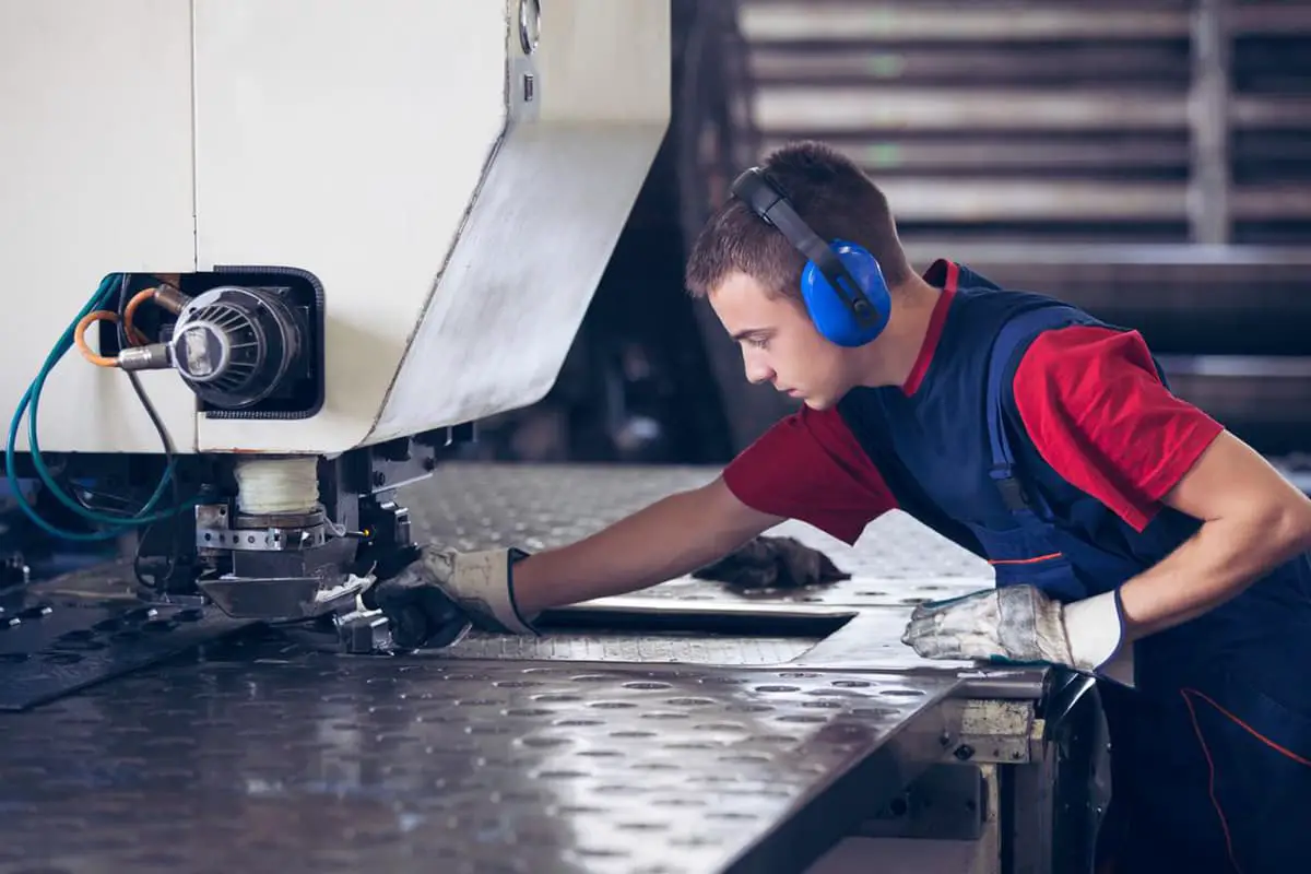
Piercing and blanking by CNC punch press
CNC punching and blanking are to use the single-chip microcomputer on the CNC punching machine to input the machining program (size, machining path, processing tool, etc.) of the sheet metal part in advance, which makes the CNC punching machine adopts various tools and a wealth of NC commands to achieve a variety of forms of processing like punching, trimming, forming etc.
CNC punching generally cannot achieve piercing and blanking with too complicated shapes.
Features:
It basically able to meet the needs of sample blanking production.
Attention problems and requirements:
CNC punching is generally suitable for punching low carbon steel, electrolytic plate, aluminum-zinc plate, aluminum plate, copper plate with T=3.5~4mm or less, and stainless steel plate with T=3mm or less.
The recommended sheet thickness for CNC punching is:
The CNC punching process has a large deformation on the copper plate, while the processing PC and the PVC plate have large processing edge burrs and low precision.
When punching, the diameter and width of the tool used must be greater than the thickness of the material. For example, a tool with a diameter of Φ1.5 cannot punch a material of 1.6 mm.
Materials below 0.6mm are generally not processed by NCT.
Stainless steel materials are generally not processed by NCT. (Of course, 0.6~1.5mm material can be processed by NCT, but the tool wear is large, and the probability of scrap rate in the field processing is much higher than other GI materials.)
Piercing and blanking of other shapes are desirably as simple and uniform as possible.
The size of the CNC punch should be normalized, such as round holes, hexagonal holes, and the minimum width of the process groove is 1.2mm.
Piercing and blanking by cold punch die
For punching and blanking of parts with large output and small size, specially designed sheet metal stamping dies are made and used for increased production efficiency.
It generally consists of a punch and a die.
The die is generally include: press-in type, and inlaid type.
Punches are generally include: round type, can be replaced; combined type; quick loading and unloading type.
The most common dies are:
Features:
Because the punching and blanking with cold die can basically be completed by one stamping, the efficiency is high, the consistency is good, and the cost is low.
Therefore, for the structural parts with an annual processing capacity of more than 5,000 pieces and the part size is not too large, the processing plant generally performs cold die processing.
In the design of the structure, it is necessary to consider the design of the process characteristics of the cold die processing.
For example, the parts should not have sharp corners (except for use). They should be designed to be rounded to improve the quality and life of the mold, and make the workpiece beautiful, safe and durable.
In order to meet the functional requirements, the structural shape of the part can be designed to be more complicated.
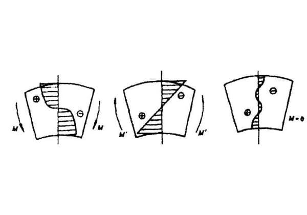
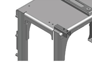
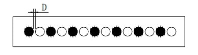
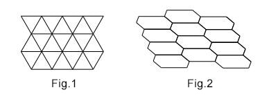
Piercing by the dense hole punch
The dense hole punch can be regarded as a kind of numerical control punch. For parts with a large number of dense holes, the punching efficiency and precision can be improved.
A specially made punching die can punch a large number of dense holes to process the workpiece.
Such as: ventilation stencil, inlet and outlet air baffle.
See Figure 1-1.
The shaded part in the figure is a dense hole mold, and the dense hole of the part can be quickly punched out by the dense hole mold. Compared to one punch, it greatly improves efficiency.
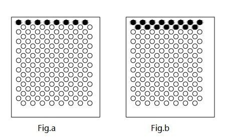
Problems and requirements for dense holes arrangement designs
The design of the dense hole on the product should consider that the processing characteristics of the dense hole punching die is repeated multiple times of punching, so the following principle should be adopted when designing the arrangement of the dense hole:
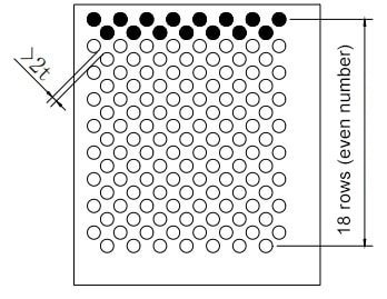
The dense hole mold of Figure 1-1 a can be designed as shown in Figure 1-4.
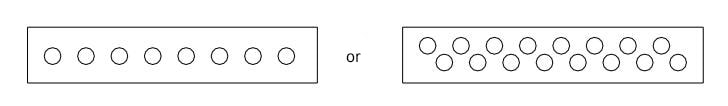
The dense hole mold of Figure 1-1 b can only be designed as shown in Figure 1-5.
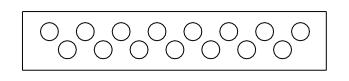
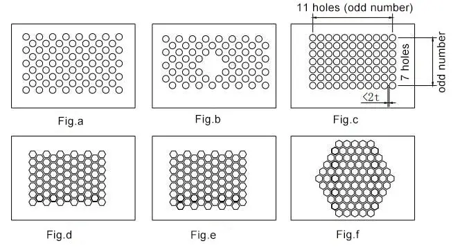
When designing the arrangement of dense holes, try to design according to the above requirements, and continuous and have certain regularity, which is convenient for opening the hole mold and reducing the stamping cost.
Otherwise, only a few punches or a number of sets of molds can be used to complete the processing.
As shown in Figure 1-6,
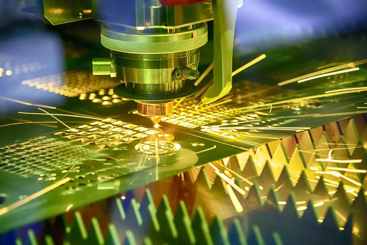
Laser cutting
Laser cutting is a non-contact cutting technology that uses electron discharge as a source of energy to focus a laser beam as a heat source by using a reflecting mirror group. This high-density light energy is used to achieve punching and blanking of sheet metal parts.
Features:
However, the cost is high, and the support table of the workpiece is damaged at the same time, and the cut surface is easy to deposit an oxide film, which is difficult to handle.
Generally only suitable for single and small batch processing.
Attention : generally only used for steel plates.
Aluminum plates and copper plates are generally not used because the material heat transfer is too fast, causing melting around the incision, which does not guarantee processing accuracy and quality.
The laser cutting end face has a layer of oxide scale, which can not be washed off, and the cutting end face with special requirements should be polished;
Laser cutting dense holes are more deformed, generally do not use the laser to cut dense holes.
Wire EDM
Wire cutting is a processing method in which a workpiece and a wire (molybdenum wire, copper wire) are each used as a pole and kept at a certain distance, and a spark gap is formed when a voltage is high enough, and the workpiece is subjected to electrolytic etching. The removed material is carried away by the working fluid.
Features: high processing accuracy, but low processing speed, high cost, and will change the surface properties of the material.
Generally used for mold processing, not used for processing production parts.
Some square holes of the profile panels have no rounded corners that cannot be milled, and because aluminum alloys cannot be cut by laser, if there is no punching space, they can only be punched by wire EDM.
The speed is very slow, the efficiency is very low, and it is not suitable for mass production. The design should avoid this situation.
Comparison of the three commonly used blanking and piercing methods
Table 1-4 Comparison of three common punching and blanking processing characteristics
Note: The following data is data for cold rolled steel sheets.
| Laser | Cutting | Punch | |
|---|---|---|---|
| Machinable material | steel plate | Steel plate, copper plate, aluminum plate | Steel plate, copper plate, aluminum plate |
| Machinable material thickness | 1mm ~ 8mm | 0.6mm ~ 3mm | generally <4mm |
| Processing minimum size (normal cold rolled steel plate) | Minimum slit 0.2mm | Punching hole Ø≧t | Punching hole Ø≧t |
| Minimum circle 0.7mm | Square hole small edge W≧t | Square hole small edge W≧t | |
| Long groove width W≧t | Long groove width W≧2t | ||
| Minimum distance between hole and hole, hole and edge | ≧t | ≧t | ≧1t |
| Preferably the distance between the holes and holes, holes and the edges | ≧1.5t | ≧1.5t | ≧1.5t |
| General machining accuracy | ±0.1mm | ±0.1mm | ±0.1mm |
| Processing range | 2000X1350 | 2000X1350 | |
| Appearance effect | Smooth outer edge, a layer of scale on the cut end face | Large raw edges with burrs | a small amount of raw edges |
| Curve effect | Smooth, changeable shape | Large burrs and regular shapes; | Smooth, changeable shape |
| Processing speed | Cutting the outer circle quickly | Punching dense holes fast | fastest |
| Processing text | Etching, shallower, unlimited size | Stamped concave text with deeper symbols; size is limited by the mold | Stamped concave text with deeper symbols; size is limited by the mold |
| Forming | can’t | Concave, counterbore, small stretch, etc. | Can achieve more complex shapes |
| Processing cost | Higher | Low | Low |
Technical design of the arrangement
In large-volume and medium-volume production, the material cost of parts accounts for a large proportion.
The full and effective use of materials is an important economic indicator for sheet metal production.
Therefore, under the condition that the design requirements are not affected, the structural designer should strive to adopt the arrangement method without waste or less waste.
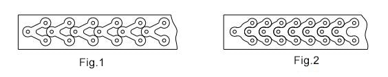
As shown in Figure 1-7, there is no waste arrangement.
Some parts have a slightly changed shape, which can save a lot of material.
As shown in Figure 1-8, Figure 2 uses less material than Figure 1.
Processability of blanking parts
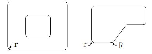
For the CNC punching machine to process the outer radius, a special external tool is required. In order to reduce the outer circle tool, the standard corner rounding of this manual as shown in Figure 1-9 is:
1) 90 degree right angle corner rounding series, the radius is r2.0, r3.0, r5.0, r10
2) The 135-degree beveled corner radius is uniform to R5.0
Punching is preferred to use round holes.
The round holes should be selected according to the series of round holes specified in the sheet metal mold manual.
This can reduce the number of round hole tools and reduce the time for blade changing on CNC punching.
Due to the punch strength limitations, the aperture cannot be too small. Its minimum aperture is related to the material thickness.
The minimum diameter of the hole should not be less than the value shown in Table 1-5 below.
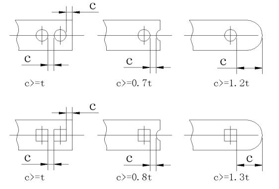
Table 1-5 Minimum size for punching with a common punch
| The minimum diameter or minimum edge length of the punch (t is the material thickness) | |||
|---|---|---|---|
| Material | Round hole D(D is diameter) | Square hole L(L is edge length) | Waist hole, rectangular hole a(a is the min edge length) |
| High and medium carbon steel | ≥1.3t | ≥1.2t | ≥1t |
| Low carbon steel and brass | ≥1t | ≥0.8t | ≥0.8t |
| Aluminum, zinc | ≥0.8t | ≥0.6t | ≥0.6t |
| Cloth bakelite laminate | ≥0.4t | ≥0.35t | ≥0.3t |
The distance between the holes, and between the hole and the edge should not be too small. The value is shown in Figure 1-10:
The precision between the hole and the shape, the hole and the hole processed by the composite mold is easy to ensure during the stamping process of the mold.
Besides, the processing efficiency is high, and the maintenance cost of the mold is convenient for maintenance.
Considering the above reasons, the distance between the hole and the hole, if the distance between the hole and the shape can meet the minimum wall thickness requirement of the composite mold, the process is better, as shown in Figure 1-11:
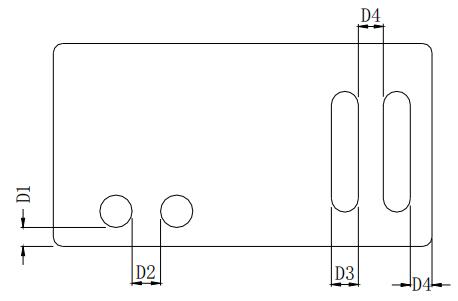
Table 1-6 Minimum size of the edge of the composite die blanking
| t (<0.8 ) | t (0.8~1.59) | t (1.59~3.18) | t (>3.2) | |
|---|---|---|---|---|
| D1 | 3mm | 2t | ||
| D2 | 3mm | 2t | ||
| D3 | 1.6mm | 2t | 2.5t | |
| D4 | 1.6mm | 2t | 2.5t | |
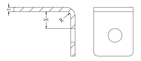
As shown in Figure 1-12, first piercing and then bending. In order to ensure that the hole is not deformed, the minimum distance between the hole and the flange X≥2t+R
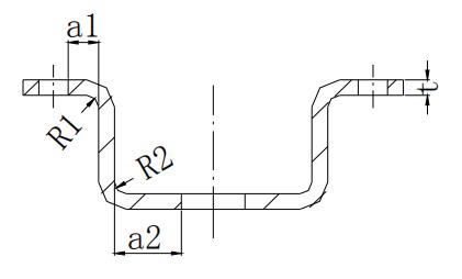
When punching holes on the deep drawing parts, see Figure 1-13, in order to ensure the shape and positional accuracy of the holes and the strength of the mold, the hole wall and the straight wall of the parts should be kept at a certain distance, that is, the distances a1 and a2 should meet the following requirements:
In the formula, R1, R2 is the corner radius, and t is the thickness.
Processing precision of blanking parts
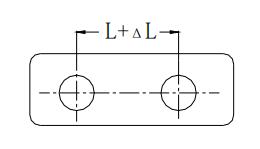
Table 1-7 Tolerance Table of Hole Center Distance (Unit:mm)
| Ordinary punching accuracy | Advanced punching accuracy | |||||
|---|---|---|---|---|---|---|
| Nominal size L | Nominal size L | |||||
| Thickness | <50 | 50~150 | 150~300 | <50 | 50~150 | 150~300 |
| <1 | ±0.1 | ±0.15 | ±0.20 | ±0.03 | ±0.05 | ±0.08 |
| 1~2 | ±0.12 | ±0.20 | ±0.30 | ±0.04 | ±0.06 | ±0.10 |
| 2~4 | ±0.15 | ±0.25 | ±0.35 | ±0.06 | ±0.08 | ±0.12 |
| 4~6 | ±0.20 | ±0.30 | ±0.40 | ±0.08 | ±0.10 | ±0.15 |
Note: All holes should be punched out once when using the values in this table.
Selection principle of stamping part design size
1) The design dimensional reference of the stamped part is as close as possible to the manufactured positioning reference, so that the manufacturing error of the dimension can be avoided.
2) The hole size reference of the stamping part should be selected as far as possible from the beginning to the end of the stamping process, and should not be associated with the part participating in the deformation.
3) For parts that are dispersed and stamped on different molds in multiple steps, the same positioning reference should be used as much as possible.
Table 1-8 Tolerance table of hole center and edge distance
| Thickness | Sizes b | |||
|---|---|---|---|---|
| ≤50 | 50<b≤120 | 120<b≤220 | 220<b≤360 | |
| <2 | ±0.2 | ±0.3 | ±0.5 | ±0.7 |
| ≥2~4 | ±0.3 | ±0.5 | ±0.6 | ±0.8 |
| >4 | ±0.4 | ±0.5 | ±0.8 | ±1.0 |
Note: This table is suitable for hole punching after blanking.
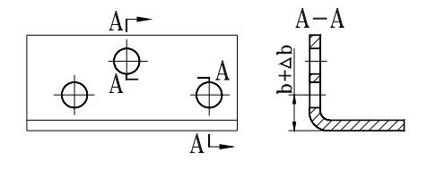
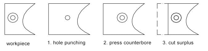
Secondary cutting
Secondary cutting is also called secondary blanking, or additional cutting (very poor process, should be avoided when designing).
The secondary cutting is that the stretching has a deformation of the material. When the bending deformation is large, the blanking is increased. Forming first, then cutting holes or contours to remove the reserved material and obtain the complete correct structure size.
Application: when the tensioning boss is close to the edge, an additional cut must be performed.
Take the counterbore as an example, as shown in Figure 1-16.
You can read this post to learn every detail about sheet metal bending.
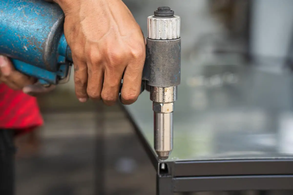
Common forms of riveted nuts are self-clinching standoff, self-clinching nut, anchor rivet nut, pull rivet nut, and floating rivet nut.
Self-clinching standoff
Pressing riveting means that in the riveting process, under the external pressure, the riveting part plastically deforms the base material, and is squeezed into the prefabricated groove specially designed in the riveted screw and nut structure, thereby realizing the reliable connection of the two parts.
There are two types of non-standard nuts for riveting, one is a Self-clinching standoff and the other is a self-clinching nut.
The connection to the substrate is achieved using such a riveted form.
Such riveting forms typically require the riveted part to have a hardness greater than the hardness of the substrate.
Ordinary low carbon steel, aluminum alloy plate and copper plate are suitable for crimping the self-clinching standoff.
For stainless steel and high carbon steel sheets, because of the hard material, a special high-strength rivet nut column is required, which is not only expensive, but also difficult to crimp, and the crimping is not reliable, and it is easy to fall off after crimping.
In order to ensure reliability, manufacturers often need to add welding on the side of the nut column, which is not good in the process.
Therefore, the sheet metal parts with the rivet nut column and the rivet nut are not as stainless steel as possible.
This is also the case with rivet screws and rivet nuts, which are not suitable for use on stainless steel sheets.
The crimping process of the rivet nut column is shown in Figure 1-41:

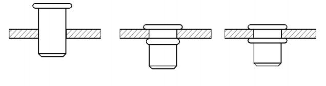
Self-clinching rivet nut
The crimping process of the rivet screw is shown in Figure 1-42:
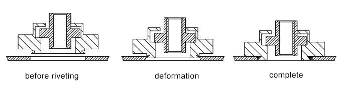
Anchor rivet nut
Anchor riveting means that during the riveting process, part of the material of the riveted screw or nut is plastically deformed under the action of an external force, and a tight fit is formed with the base material, thereby realizing a reliable connection of the two parts.
The commonly used ZRS is connected to the substrate by this riveting type.
The riveting process is relatively simple, and the joint strength is low, and is usually used to limit the height of the fastener and to withstand a small torque. As shown in Figure 1-43:
Pull rivet nut
The pull riveting means that the riveting member is plastically deformed under the action of external tension during the riveting process.
The position of the deformation is usually in a specially designed part, and the substrate is clamped by the deformation portion to achieve a reliable connection.
The commonly used rivet nuts are connected to the substrate by this riveting type.
The riveting is riveted using a special rivet gun, which is often used in places where the installation space is small and it is not possible to use universal riveting tools, such as closed pipes. As shown in Figure 1-44:
Floating rivet nut
Some of the rivet nuts on the sheet metal structure, because the overall chassis structure is complex, the accumulation error of the structure is too large, so that the relative position error of these rivet nuts is large, which makes assembly of other parts difficult.
This is a good improvement after the use of a riveted floating nut at the position of the corresponding rivet nut.
As shown in Figure 1-45: (Note: there must be enough space in the riveting position)
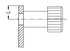
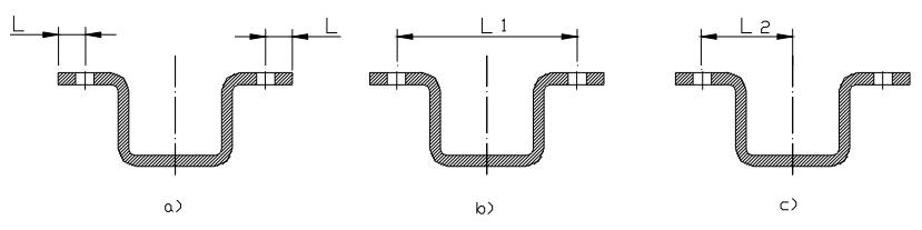
Anchor rivet nut or self-clinching rivet nut to the side distance
The anchor rivet nut or the self-clinching rivet nut are riveted together with the sheet by squeezing the sheet.
When the anchor riveting or self-clinching riveting is too close to the edge, it is easy to deform this part.
When there is no special requirement, the minimum distance between the centerline of the riveted fastener and the edge of the sheet should be greater than L, see Figure 1-46.
Otherwise special clamps must be used to prevent the edges of the sheet from being deformed by force.
Factors affecting the quality of riveting
There are many factors affecting the quality of riveting. To sum up, there are mainly the following: substrate performance, bottom hole size, and riveting method.
1) Substrate properties.
When the hardness of the substrate is appropriate, the riveting quality is good, and the force of the riveting member is good.
2) Bottom hole size.
The size of the bottom hole directly affects the quality of the riveting, if the opening is large, then the gap between the substrate and the rivet is large.
For the riveting, there must not be enough deformation to fill the groove on the riveting piece, so the shearing force is insufficient, which directly affects the thrust resistance of the riveting nut (nail).
For the rivet screw, the bottom hole is too large, and the pressing force generated by the plastic deformation during the riveting process becomes small, which directly affects the thrust resistance and the torsion resistance of the rivet screw (female).
The same for the riveting, the bottom hole is too large, so the effective friction between the two pieces after plastic deformation is reduced, affecting the quality of the riveting.
The size of the bottom hole is small, and although the force of the riveting can be increased to a certain extent, the appearance quality of the riveting is likely to be poor.
The riveting force is large, the installation is inconvenient, and the deformation of the bottom plate is easily caused, which affects the production efficiency of the riveting work and the quality of the riveting.
3) Riveting method.
It has been introduced in the previous section. Riveting screws and nuts should pay great attention to the occasions in the process of use. Different situations and different force requirements require different types.
If it is not used properly, it will reduce the force range of the riveted screws and nuts, causing the connection to fail.
Here are a few examples to illustrate the correct use of the normal situation.
1) Do not install steel or stainless steel riveted fasteners before the aluminum plate is anodized or surface-treated.
2) If there is too much riveting on the same straight line, there is no place for the extruded material to flow, which will generate large stress and bend the workpiece into a curved shape.
3) Try to ensure that the surface of the board is plated before installing the riveted fasteners.
4) M5, M6, M8, M10 nuts are generally welded. Too large nuts generally require high strength. Arc welding can be used. Below M4 (including M4) the anchor rivet nut should be used. If it is electroplated, the rivet nut with electroless plating can be used.
5) When riveting the nut on the bent side, in order to ensure the riveting quality of the riveted nut, it is necessary to pay attention to: 1.
The distance from the edge of the riveting hole to the side of the bend must be greater than the deformation zone of the bent part. 2.
The distance L from the center of the riveted nut to the inside of the bent side should be greater than the sum of the outer cylindrical radius of the riveted nut and the inner radius of the bend. That is, L>D/2+r.
The projection weld nut (spot weld nut) is widely used in the design of sheet metal parts.
However, in many designs, the size of the pre-hole is not in accordance with the standard and cannot be accurately positioned.
The structural type and dimensions are as shown in Figure 1-47 and Figure 1-48. The recommended values for the hole diameter D0 and the thickness H before welding the steel plate for welding are as specified in Table 1-17.
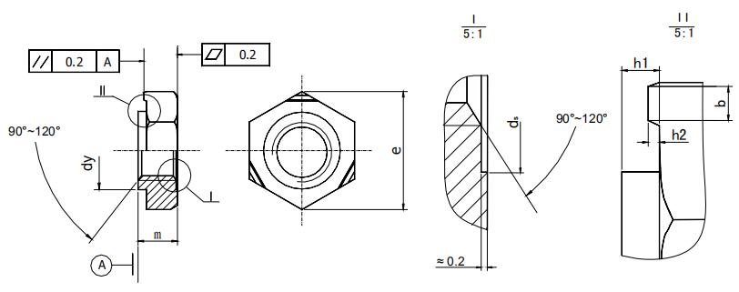
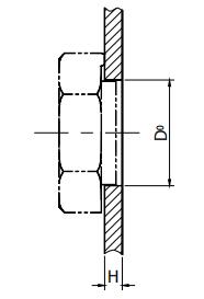
Table 1-17 Welded hex nut dimensions and opening thickness of corresponding steel plate (mm)
| Thread size (D or D×P) | M4 | M5 | M6 | M8 | M10 | M12 | M16 | |
|---|---|---|---|---|---|---|---|---|
| ─ | ─ | ─ | M8×1 | M10×1 | M12×1. 5 | M16×1. 5 | ||
| ─ | ─ | ─ | ─ | (M10×1.25) | (M12×1. 25) | ─ | ||
| e | min | 9.83 | 10.95 | 12.02 | 15.38 | 18.74 | 20.91 | 26.51 |
| dy | max | 5.97 | 6.96 | 7.96 | 10.45 | 12.45 | 14.75 | 18.735 |
| min | 5.885 | 6.87 | 7.87 | 10.34 | 12.34 | 14.64 | 18.605 | |
| h1 | max | 0.65 | 0.7 | 0.75 | 0.9 | 1.15 | 1.4 | 1.8 |
| min | 0.55 | 0.6 | 0.6 | 0.75 | 0.95 | 1.2 | 1.6 | |
| h2 | max | 0.35 | 0.4 | 0.4 | 0.5 | 0.65 | 0.8 | 1 |
| min | 0.25 | 0.3 | 0.3 | 0.35 | 0.5 | 0.6 | 0.8 | |
| m | max | 3.5 | 4 | 5 | 6.5 | 8 | 10 | 13 |
| min | 3.2 | 3.7 | 4.7 | 6.14 | 7.64 | 9.64 | 12.3 | |
| D0 | max | 6.075 | 7.09 | 8.09 | 10.61 | 12.61 | 14.91 | 18.93 |
| min | 6 | 7 | 8 | 10.5 | 12.5 | 14.8 | 18.8 | |
| H | max | 3 | 3.5 | 4 | 4.5 | 5 | 5 | 6 |
| min | 0.75 | 0.9 | 0.9 | 1 | 1.25 | 1.5 | 2 | |
Note: Do not use the specifications in parentheses as much as possible.
Common coarse threaded boring size
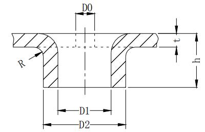
| Thread diameter M | Thickness t | Inner diameter D1 | Outer diameter D2 | Height h | Pre-punch diameter D0 | Radius |
|---|---|---|---|---|---|---|
| M2.5 | 0.6 | 2.1 | 2.8 | 1.2 | 1.4 | 0.3 |
| 0.8 | 2.8 | 1.44 | 1.5 | 0.4 | ||
| 1 | 2.9 | 1.8 | 1.2 | 0.5 | ||
| 1.2 | 2.9 | 1.92 | 1.3 | 0.6 | ||
| M3 | 1 | 2.55 | 3.5 | 2 | 1.4 | 0.5 |
| 1.2 | 3.5 | 2.16 | 1.5 | 0.6 | ||
| 1.5 | 3.5 | 2.4 | 1.7 | 0.75 | ||
| M4 | 1 | 3.35 | 4.46 | 2 | 2.3 | 0.5 |
| 1.2 | 4.5 | 2.16 | 2.3 | 0.6 | ||
| 1.5 | 4.65 | 2.7 | 1.8 | 0.75 | ||
| 2 | 4.56 | 3.2 | 2.4 | 1 | ||
| M5 | 1.2 | 4.25 | 5.6 | 2.4 | 3 | 0.6 |
| 1.5 | 5.75 | 3 | 2.5 | 0.75 | ||
| 2 | 5.75 | 3.6 | 2.7 | 1 | ||
| 2.5 | 5.75 | 4 | 3.1 | 1.25 |
The minimum distance from the tapping to the bending edge
Table 1-19 Distance between the tapping center and the bending edge H value comparison table
| Thickness/thread diameter | 1 | 1.2 | 1.5 | 2 |
|---|---|---|---|---|
| M3 | 6.2 | 6.6 | – | – |
| M4 | 7.7 | 8 | – | |
| M5 | – | 7.6 | 8.4 | – |
Table 1-20 Comparison of the rivet nut, self-clinching nut, pull riveting, and the tapping
| Connection method / feature | Anchor rivet nut | self-clinching rivet nut | pull riveting | flanging & tapping |
|---|---|---|---|---|
| Processability | it is good | good | good | average |
| Sheet metal requirements | Stainless steel riveting, easy to fall off | Stainless steel riveting is very poor, use special rivet nuts, and need spot welding | none | Thin plate and copper, aluminum soft material easy to slip |
| Precision | good | good | good | average |
| Durability | good | good | good | Copper and aluminum soft materials are poor, other material threads have 3 to 4 buckles or more |
| Cost | high | high | average | low |
| quality | good | good | good | average |
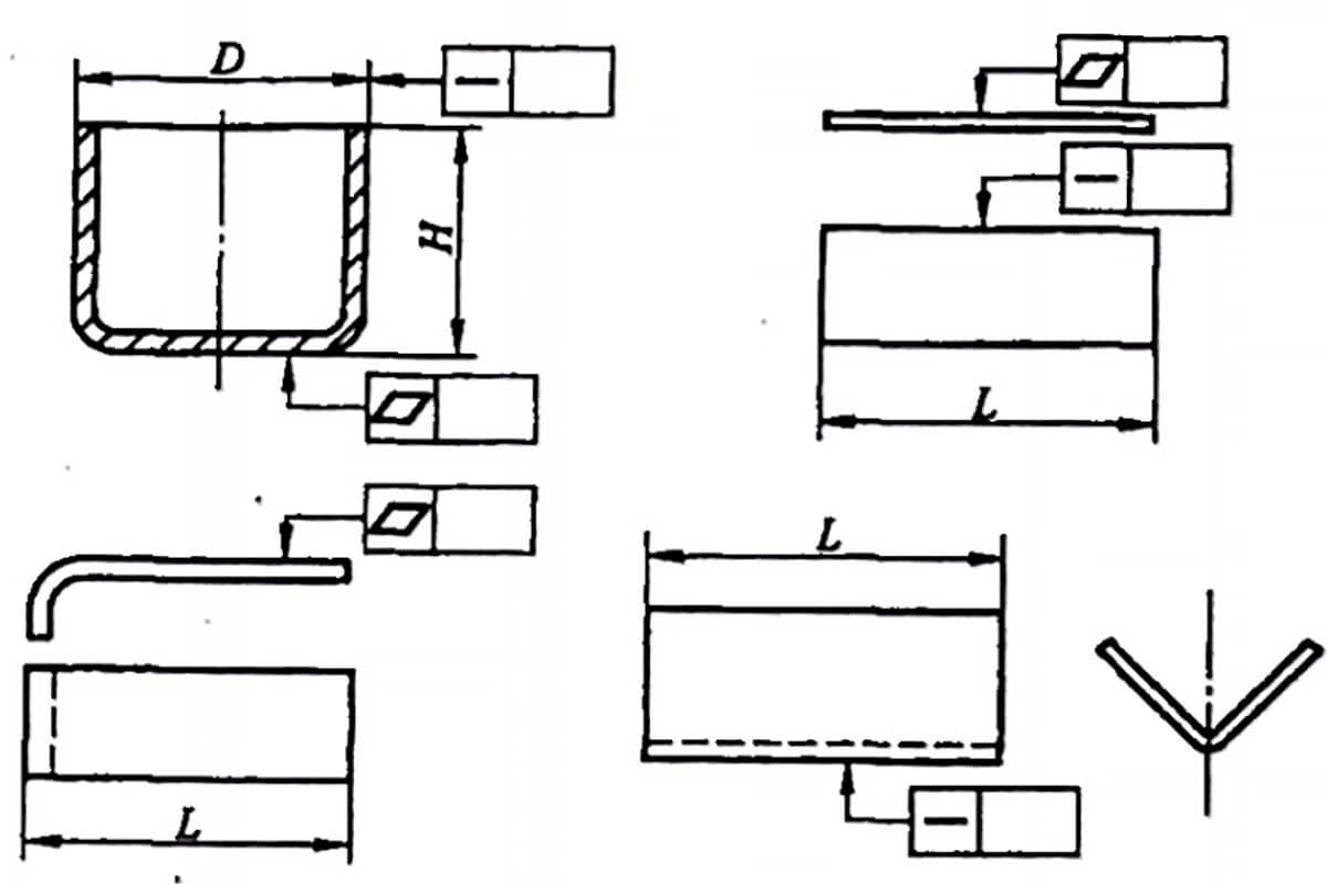
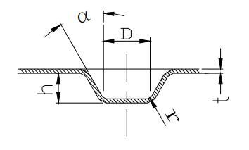
The sheet metal stretch is shown in Figure 1-50.
Sheet metal stretch considerations:
In the shape and size of the convex sheet metal, several series sizes are specified in the sheet metal mold manual. There is a corresponding Form model in the Intralink library.
The design should be selected according to the size specified in the manual, and the Form mold in the library is directly used.
Limit size of the convex pitch and convex margin
Table 1-21 Limit dimensions of the convex pitch and the convex margin
| Schematic | L | B | D |
|---|---|---|---|
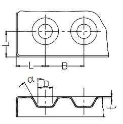 | 6.5 | 10 | 6 |
| 8.5 | 13 | 7.5 | |
| 10.5 | 15 | 9 | |
| 13 | 18 | 11 | |
| 15 | 22 | 13 | |
| 18 | 26 | 16 | |
| 24 | 34 | 20 | |
| 31 | 44 | 26 | |
| 36 | 51 | 30 | |
| 43 | 60 | 35 | |
| 48 | 68 | 40 | |
| 55 | 78 | 45 |
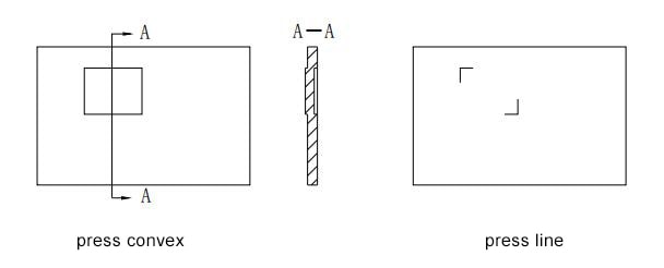
As shown in 1-52, a 0.3-inch half-cut embossing on sheet metal can be used as a sticker for a label or the like to improve the reliability of the label.
Such a semi-cutting concave, the deformation is much smaller than the normal stretching, but there is still a certain deformation for a large-area cover plate and a bottom plate that is not bent or has a small bending height.
Alternative method: Two right-angle lines can be punched in the labeling range to improve the deformation.
However, the reliability of the label attachment is reduced.
This method can also be used for processing such as product coding, production date, version, and even pattern.
Pressing the ribs on the plate-shaped metal parts, see Figure 1-53, helps to increase the structural rigidity.
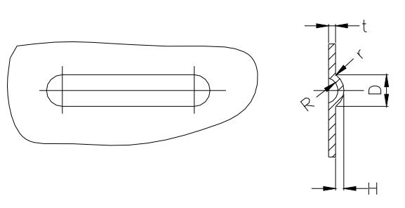
As shown in Figure 1-54,
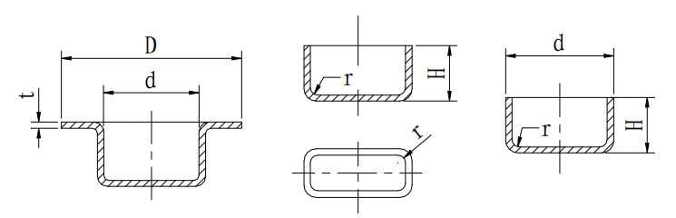
The drilling riveting is a riveting method between sheet metal, mainly used for the connection of coated steel plates or stainless steel plates.
One of the parts is punched, and the other part is punched and cuffed to make it a non-detachable connector.
Advantages: the flange is matched with the straight hole, and it has the positioning function itself. The riveting strength is high, and the riveting efficiency through the mold is also high.
The specific way is as shown in Figure 1-55:
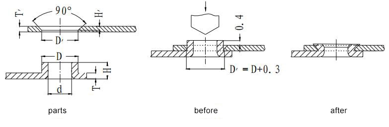
Table 1-22 Drilling riveting dimensions
| Parameter | Thickness T(mm) | Flanging height H(mm) | Flanging outer dia. D(mm) | |||||||||||
|---|---|---|---|---|---|---|---|---|---|---|---|---|---|---|
| No. | 3 | 3.8 | 4 | 4.8 | 5 | 6 | ||||||||
| Corresponding straight hole inner dia. d and pre-punching hole d0 | ||||||||||||||
| d | d0 | d | d0 | d | d0 | d | d0 | d | d0 | d | d0 | |||
| 1 | 0.5 | 1.2 | 2.4 | 1.5 | 3.2 | 2.4 | 3.4 | 2.6 | 4.2 | 3.4 | ||||
| 2 | 0.8 | 2 | 2.3 | 0.7 | 3.1 | 1.8 | 3.3 | 2.1 | 4.1 | 2.9 | 4.3 | 3.2 | ||
| 3 | 1 | 2.4 | 3.2 | 1.8 | 4 | 2.7 | 4.2 | 2.9 | 5.2 | 4 | ||||
| 4 | 1.2 | 2.7 | 3 | 1.2 | 3.8 | 2.3 | 4 | 2.5 | 5 | 3.6 | ||||
| 5 | 1.5 | 3.2 | 2.8 | 1 | 3.6 | 1.7 | 3.8 | 2 | 4.8 | 3.2 | ||||
Note: With the general principle H=T+T’+(0.3~0.4)
D = D’-0.3;
D-d=0.8T
When T≧0.8mm, the wall thickness of the flanged hole is 0.4T.
When T<0.8mm, the wall thickness of the flange is usually 0.3mm. H is usually 0.46±0.12
In the sheet metal riveting method, there is also a riveting method that is the Tox riveting.
The principle is that two stacks are placed together, as shown in Figure 1-56.
Stamping and drawing using a mold, mainly used for the connection of coated steel sheets or stainless steel sheets.
It has the advantages of energy-saving, environmental protection and high efficiency.
In the past, the chassis of the communication industry used more riveting, but the quality control of mass production was difficult. It has been applied less and is not recommended.
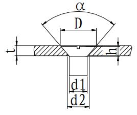
The structural dimensions of the screw counterbore are selected as shown in the following table.
For the countersunk head of the countersunk screw, if the plate is too thin, it is difficult to ensure the via d2 and the counterbore D at the same time, and the via d2 should be preferentially guaranteed.
The countersunk head and via for countersunk screws: (Selected sheet thickness t is preferably greater than h)
Table 1-23 Dimensions of screw counterbore
 | d1 | M2 | M2.5 | M3 | M4 | M5 |
|---|---|---|---|---|---|---|
| d2 | Φ2.2 | Φ2.8 | Φ3.5 | Φ4.5 | Φ5.5 | |
| D | Φ4.0 | Φ5.0 | Φ6.0 | Φ8.0 | Φ9.5 | |
| h | 1.2 | 1.5 | 1.65 | 2.7 | 2.7 | |
| Preferred min thickness | 1.2 | 1.5 | 1.5 | 2 | 2 | |
| α | 90° | |||||
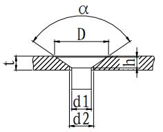
Table 1-24 Dimensions of Counterbore Holes for Hole Countersunk Rivets
 | d1 | Φ2 | Φ2.5 | Φ3 | Φ4 | Φ5 |
|---|---|---|---|---|---|---|
| d2 | Φ2.2 | Φ2.7 | Φ3.3 | Φ4.3 | Φ5.3 | |
| D | Φ4.0 | Φ5.0 | Φ5.5 | Φ7.0 | Φ9.0 | |
| h | 1 | 1.1 | 1.2 | 1.6 | 2 | |
| α | 120° | |||||
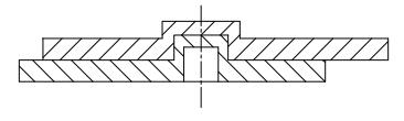
The connection of sheet metal is completed by M3 countersunk screws.
If the thickness of the plated hole is 1 mm, it is problematic according to the conventional method.
However, in the actual design, a large number of such problems are encountered.
The rivet nut is used below, and the diameter of the counterbore is 6mm, which can effectively complete the connection, as shown in the figure.
This size is used in a large number of insert box.
It is important to note that this type of connection requires that the bottom nut is anchor rivet nuts.
The self-clinching rivet nut and the tapping tap cannot complete the tightening connection.
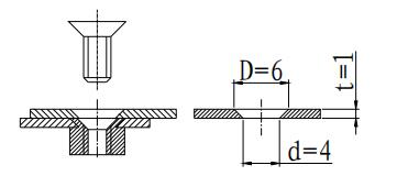
In order to standardize such dimensions, the d/D should be as follows:
Table 1-25 Unification of thin plate counterbore
| Sheet thickness | 1 | 1.2 | 1.5 |
|---|---|---|---|
| M3 | 4/6 | 3.6/6.0 | 3.5/6 |
| M4 | — | — | 5.8/8.8 |

As the founder of MachineMFG, I have dedicated over a decade of my career to the metalworking industry. My extensive experience has allowed me to become an expert in the fields of sheet metal fabrication, machining, mechanical engineering, and machine tools for metals. I am constantly thinking, reading, and writing about these subjects, constantly striving to stay at the forefront of my field. Let my knowledge and expertise be an asset to your business.