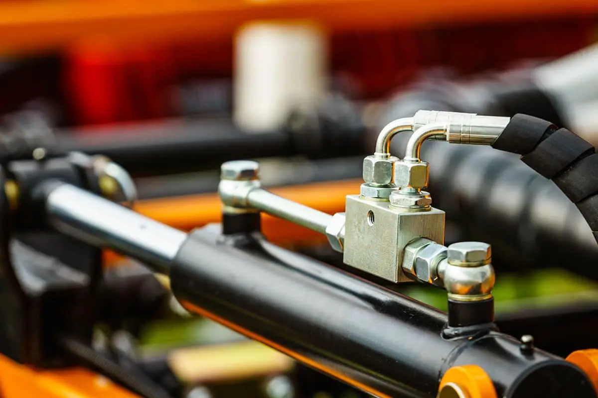
Hydraulic cylinders: the powerhouse behind countless machines. In this article, an experienced mechanical engineer shares insider knowledge on these essential components. Discover how they work, their applications, and key considerations for selecting the right one for your project. Get ready to gain a deeper understanding of these engineering marvels.
Hydraulic oil, when compressed into a hydraulic cylinder, generates significant pressure. This pressure is utilized in numerous mechanical devices, and today we will discuss the specifics of hydraulic cylinders.
A hydraulic cylinder is a hydraulic actuator that transforms hydraulic energy into mechanical energy, performing linear reciprocating motions (or oscillating movements). Its structure is simple, and its operation is reliable.
When it is used to perform reciprocating motions, it can eliminate the need for deceleration devices, and there is no transmission gap, ensuring smooth motion. Therefore, it is widely used in various hydraulic systems of machinery.
The output force of a hydraulic cylinder is directly proportional to the effective area of the piston and the pressure difference on both sides of it. A hydraulic cylinder essentially consists of a cylinder and cylinder head, piston and piston rod, sealing device, buffering device, and exhaust device.
The buffering and exhaust devices depend on the specific application, while the other devices are indispensable.
I. Composition of the Hydraulic Cylinder
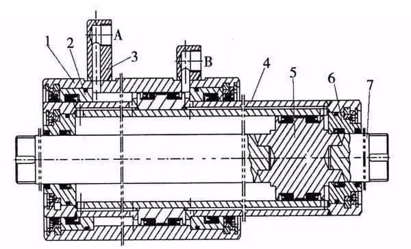
A hydraulic cylinder typically consists of a rear end cap, cylinder, piston rod, piston assembly, front end cap, and other main components.
To prevent oil leakage from the hydraulic cylinder or leakage from the high-pressure chamber to the low-pressure chamber, sealing devices are installed between the cylinder and end cap, piston and piston rod, piston and cylinder, and piston rod and front end cap.
On the outer side of the front end cap, a dust protection device is also installed. To prevent the piston from striking the cylinder cap when quickly returning to the stroke end, a buffering device is set at the end of the hydraulic cylinder, and sometimes an exhaust device is also required.
Schematic Diagram of a Commonly Used Hydraulic Cylinder
The cylinder is the main part of the hydraulic cylinder. It forms a closed chamber with the cylinder cap and other parts to drive the piston to move.
Cylinder Cap:
The cylinder cap is installed at both ends of the hydraulic cylinder, forming a tight oil chamber with the cylinder. Connection methods usually include welding, threads, bolts, keys, and tie rods. The choice depends on factors such as working pressure, cylinder connection method, and operating environment.
Piston Rod:
The piston rod is the main element of the hydraulic cylinder for transmitting force. The material is generally medium carbon steel (such as 45# steel). The piston rod is subjected to thrust, tension, or bending moment during cylinder operation. Ensuring its strength is necessary, and its fitting with the guide sleeve, where it often slides, should be appropriate.
Piston:
The piston is the main element for converting hydraulic energy into mechanical energy. Its effective working area directly affects the force and movement speed of the hydraulic cylinder. There are several forms of connection between the piston and the piston rod, including snap ring type, bushing type, and nut type.
Guide Sleeve:
The guide sleeve guides and supports the piston rod. It requires high precision, low friction resistance, good wear resistance, and the ability to withstand the pressure, bending force, and impact vibration of the piston rod.
It is equipped with a sealing device to ensure the seal of the rod chamber, and a dust ring on the outside to prevent impurities, dust and moisture from damaging the seal.
Buffering Device:
When the piston and piston rod move under hydraulic pressure, they have a significant momentum. When they reach the end cap and bottom part of the cylinder, they can cause mechanical collision, resulting in a high impact pressure and noise. The buffering device is used to prevent this collision.
Its working principle is to convert the kinetic energy of the hydraulic oil in the low-pressure chamber of the cylinder (all or part of it) into heat energy through throttling. The heat energy is then carried out of the hydraulic cylinder by the circulating oil.
The buffering device is divided into two types: constant throttling area buffering device and variable throttling buffering device.
II. Principles of Hydraulic Transmission
Hydraulic transmission utilizes oil as the working medium, transmitting motion through changes in sealed volume and power through internal pressure within the oil.
Power Component: Transforms the mechanical energy of the prime mover into hydraulic energy (pressure energy), for example, the hydraulic pump.
Actuating Component: Converts the hydraulic energy input from the pump into mechanical energy, driving the working mechanism. Examples include hydraulic cylinders and motors.
Control Component: Regulates and controls the pressure, flow, and direction of the oil. Examples include pressure control valves, flow control valves, and direction control valves.
Auxiliary Component: Connects the above three components into a system, serving functions like oil storage, filtration, measurement, and sealing. Examples include pipework and connectors, oil tanks, filters, accumulators, seals, and control instruments.
III. Classification of Hydraulic Cylinders by Structure
Piston-type Hydraulic Cylinder:
A single piston rod hydraulic cylinder has a piston rod at only one end. Both its inlet and outlet oil ports A and B can transmit pressurized oil or return oil, enabling bidirectional movement, hence it’s called a double-action cylinder.
Telescopic Hydraulic Cylinder:
Features a two-stage or multi-stage piston. In a telescopic hydraulic cylinder, the sequence of piston extension is from largest to smallest, while the retraction sequence without a load is generally from smallest to largest.
Telescopic cylinders can achieve longer strokes, but their retracted length is shorter, making the structure compact. This type of hydraulic cylinder is commonly used in construction and agricultural machinery.
Swing Hydraulic Cylinder:
An output torque and reciprocating motion execution component, also known as a swing hydraulic motor. Comes in single-vane and double-vane variants. The stator block is fixed on the cylinder body, while the vane and rotor are connected. Depending on the direction of oil inflow, the vane will drive the rotor to swing back and forth.
IV. Main Parameters of Hydraulic Cylinders
The main parameters of hydraulic cylinders include pressure, flow, size specification, piston stroke, motion speed, push-pull force, efficiency, and hydraulic cylinder power, among others.
Pressure:
Pressure is the intensity of force exerted by the oil on a unit area. The calculation formula is p=F/A, where F is the load acting on the piston divided by the effective working area of the piston. On the same effective working area of a piston, the larger the load, the greater the pressure needed to overcome the load.
Based on the working pressure, hydraulic cylinders can be classified as low-pressure (70kgf/cm² or 7Mpa), medium-pressure (140kgf/cm² or 14Mpa), or high-pressure (210kgf/cm² or 21Mpa) hydraulic cylinders.
Nominal pressure series of hydraulic cylinders
0.63
1.0
1.6
2.5
4.0
6.3
10.0
16.0
25.0
31.5
40.0
Hydraulic cylinder piston stroke series
First Series
25
50
80
100
125
160
200
250
320
400
500
630
800
1000
1250
1600
2000
2500
3200
4000
Second Series
40
63
90
110
140
180
220
280
36
450
550
700
900
1100
1400
1800
2900
2800
3600
Third Series
240
260
300
340
380
420
480
530
600
650
750
850
950
1050
1200
1300
1500
1700
1900
2100
2400
2600
3000
3400
3800
Hydraulic cylinder inner diameter size series
8
40
125
(280)
10
50
(140)
320
12
63
160
(360)
16
80
(180)
400
20
(90)
200
(450)
25
100
(220)
500
32
(110)
250
Hydraulic cylinder piston rod outer diameter size series
4
18
45
110
280
5
20
50
125
320
6
22
56
140
360
8
25
63
160
10
28
70
180
12
32
80
200
14
36
90
220
16
40
100
250
Flow:
The flow is the volume of oil passing through the effective cross-sectional area of the cylinder per unit time. The calculation formula is Q=V/t=vA, where V is the volume of oil consumed in one stroke of the hydraulic cylinder piston, t is the time required for one stroke of the hydraulic cylinder piston, v is the speed of the piston rod, and A is the effective working area of the piston.
Piston Stroke:
Piston stroke refers to the distance covered by the piston in its reciprocating motion between two extremes. Generally, after the stability requirement of the cylinder is met, a standard stroke close to the actual working stroke is selected.
Piston Speed:
The motion speed is the distance the pressurized oil pushes the piston per unit time, represented as v=Q/A.
Size Specifications:
Size specifications mainly include the inner and outer diameters of the cylinder, the diameter of the piston, the diameter of the piston rod, and the dimensions of the cylinder head. These dimensions are calculated, designed, and checked based on the operating environment of the hydraulic cylinder, installation method, required push-pull force, and stroke.
V. Hydraulic Cylinder Internal Design
Design Purpose: Determined based on onsite operating temperature, working medium, and our factory’s manufacturing conditions. Dimensions of the internal structure are calculated based on the Mechanical Design Handbook.
Seal selection must be based on onsite operating temperature, environmental pollution conditions, and the working medium. Polyurethane seals cannot be used with a water-ethylene glycol medium.
The hydraulic cylinder head should ideally use a V-type combination seal to compensate for the errors in the groove processing smoothness.
The dimensions of the seal grooves must strictly adhere to the design handbook.
Generally, hydraulic cylinder piston seals use Glyd rings along with guide tapes, as Glyd rings have good high-temperature resistance and anti-pollution properties.
Typically, air cylinder seals use the Japanese NOK series. Domestic hydraulic cylinder seals should not be used as they cause too much cylinder startup resistance, leading to unstable operation or even failure.
The O-ring seal between the hydraulic cylinder head, cylinder bottom, and cylinder body should ideally have a blocking ring to compensate for manufacturing errors.
The connection between the cylinder body, cylinder head, cylinder bottom, and the swing in the middle should avoid welding, as it can cause deformation of the cylinder body. Threaded connections or other methods can be used instead.
VI. Common Hydraulic Cylinder Problems and Maintenance
Hydraulic Cylinder Oil Leak:
External leakage refers to the oil leaking from various unsealed parts to the atmosphere outside the hydraulic cylinder. The most common external leakages are from the following three places:
(1) Oil leakage from the seal between the hydraulic cylinder sleeve and the cylinder cover (or guide sleeve) (Solution: Replace with a new O-ring).
(2) Oil leakage from the relative movement between the piston rod and the guide sleeve (Solution: If the piston rod is damaged, clean it with gasoline, dry it, apply metal adhesive to the damaged area, then move the piston rod oil seal back and forth on the piston rod to scrape off excess adhesive.
Once the adhesive has fully cured, it can be put back into use. If the guide sleeve is worn, a slightly smaller diameter guide sleeve can be machined for replacement).
(3) Oil leakage caused by poor sealing of the hydraulic cylinder pipe joint (Solution: In addition to checking the sealing condition of the sealing ring, check whether the joint is correctly assembled, whether it is tightly screwed, and whether the contact surface has any scratches, etc. If necessary, replace or repair).
Internal leakage of the hydraulic cylinder refers to oil in the hydraulic cylinder internally leaking from the high-pressure chamber to the low-pressure chamber through various gaps.
Internal leakage is harder to detect and can only be judged by the system’s working condition, such as insufficient thrust, speed decline, unstable operation, or oil temperature increase. Hydraulic cylinder internal leakage generally occurs in the following two places:
(1) The static seal part between the piston rod and the piston (Solution: Install an O-ring on the sealing surface between them).
(2) The dynamic seal part between the inner wall of the cylinder sleeve and the piston (Solution: When internal leakage is detected, a strict inspection of each matching part should be conducted. The repair of the cylinder sleeve often involves boring the inner hole, followed by fitting a piston with a larger diameter).
As the founder of MachineMFG, I have dedicated over a decade of my career to the metalworking industry. My extensive experience has allowed me to become an expert in the fields of sheet metal fabrication, machining, mechanical engineering, and machine tools for metals. I am constantly thinking, reading, and writing about these subjects, constantly striving to stay at the forefront of my field. Let my knowledge and expertise be an asset to your business.
Attention all mechanical engineers and manufacturing professionals! Are you struggling with pesky anodizing defects in your aluminum products? Look no further! In this blog post, we'll dive deep into the…
Ever wondered why some materials bend easily while others remain rigid? This blog dives into the fascinating world of elastic modulus and stiffness, unraveling their crucial roles in engineering. By…
Have you ever wondered what makes a perfect circle? In the world of mechanical engineering, roundness is a crucial concept that affects the performance and longevity of rotating components. This…
In today's fast-paced manufacturing world, efficient deburring is crucial. With numerous methods available, choosing the right one can be daunting. In this blog post, we'll explore various deburring techniques, from…
Have you ever wondered what keeps the world spinning smoothly? The unsung heroes behind the scenes are bearings. These small but mighty components play a crucial role in reducing friction…
Gears are the unsung heroes of the mechanical world, quietly working behind the scenes to keep machines running smoothly. But have you ever wondered what materials these critical components are…
This article explores the top 5 cooling tower manufacturers shaping our world. Learn how these companies innovate to keep industries running smoothly and efficiently. Get ready to uncover the secrets…
Have you ever wondered what keeps our gas systems running smoothly and safely? In this article, we explore top gas regulator manufacturers, uncovering their innovations and contributions to the industry.…
Ever wondered why connecting copper and aluminum wires is problematic? This article explains the risks associated with connecting these two metals due to their differing electrochemical properties, which can lead…