Our company has developed a new high-strength nano cement fireproof safety box as part of our transformation project of scientific and technological achievements, meeting the requirements of our customers.
The safety box consists of an inner container and an outer shell, both of which are bent from cold-rolled steel plates. However, due to interference between the press brake machine and the parts, the conventional bending die cannot be used.
The challenge lies in finding a solution to allow the press brake machine to bend the U-shaped parts smoothly without any interference. This is the key to solving the process problem.
1. Process analysis of parts
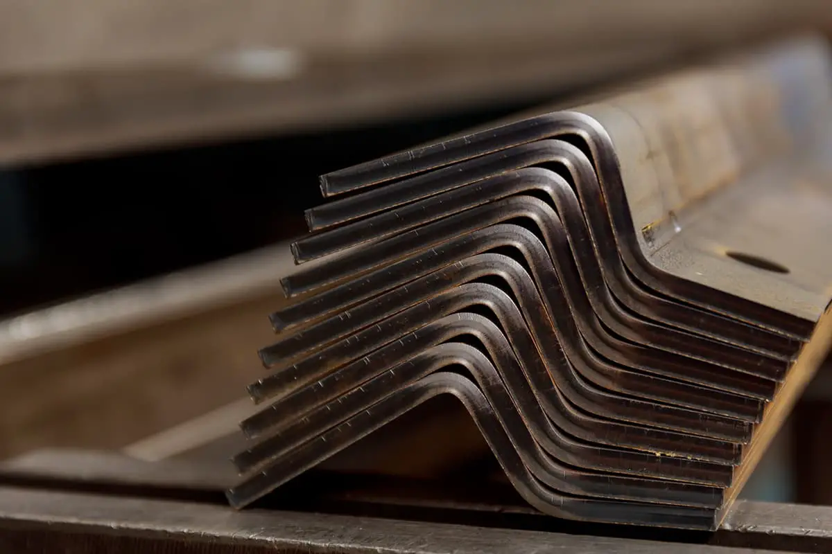
As depicted in Figures 1 and 2, the diagrams respectively show the inner container and outer shell of the safety box.
Fig. 1 Inner container Fig. 2 Outer shell
The part is manufactured from 3mm thick cold-rolled steel plate and requires bending on a press brake machine. During the bending simulation of the part model, it was found that one side of the part interfered with the panel of the machine.
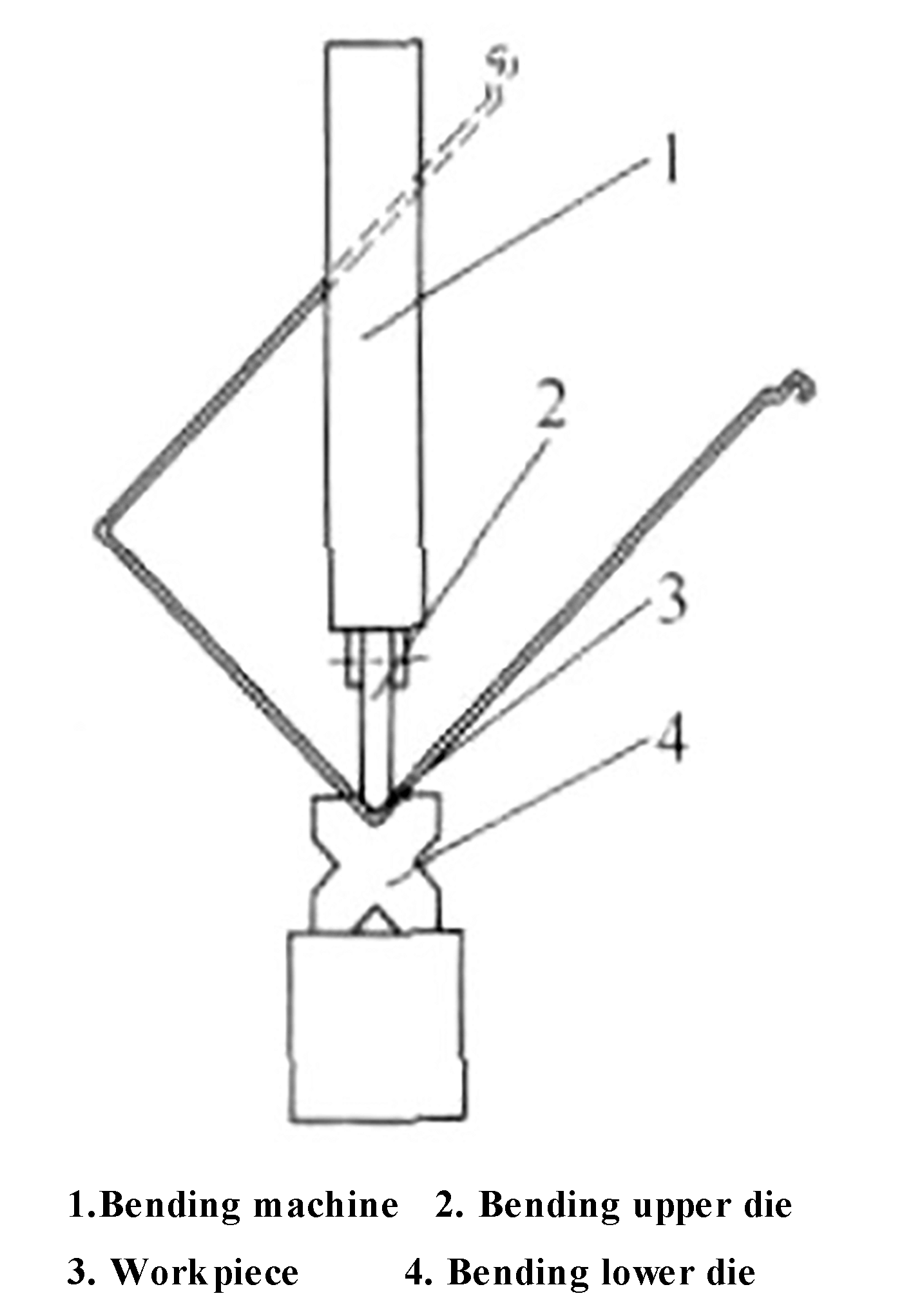
Upon further analysis, it was determined that the aspect ratio of the part was too large, reaching 1.54 and 1.52 respectively, which is significantly greater than the 1:1 ratio. Ordinarily, when bending U-shaped parts using a bending die, the maximum length-to-width ratio should not exceed 1:1. If the ratio is larger, the long side of the part will interfere with the press brake machine, as demonstrated in Figure 3.
Fig. 3 Interference phenomenon of long side of the part
Related: V & U-shaped Bend Force Calculator
2. Structure of existing press brake machine
We analyzed both the press brake machine and bending die and found the following:
The front panel of the press brake machine has a complex and bulky structure, with a thickness of approximately 80mm and is fixed in place. During the bending process, the worktable of the press brake machine and the bending die move up and down together.
It was determined that it would be impractical and impossible to modify the press brake machine to accommodate the processing of these parts.
However, making appropriate design improvements to the bending die can effectively resolve the issue without changing the structure of the press brake machine. This approach would allow for twice the outcome with half the effort, enabling the successful bending of U-shaped parts.
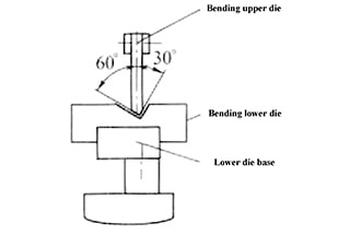
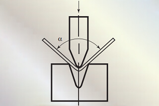
As shown in Figure 4, the conventional bending die has a symmetrical structure with a 45° angle, with a left-right orientation.
Fig. 4 The ordinary bending die
The path of the die is equivalent to the diagonal of a square. The maximum length-to-width ratio of the U-shaped part that can be bent by the die is 1:1. If this ratio is exceeded, one side of the part will come into conflict with the press brake machine, preventing the successful processing of the part.
3. Solutions of interference between parts and press brake machine
The analysis of the parts process and the cutter die structure of the press brake machine has revealed that the cause of the interference is the high length-width ratio of the U-shaped parts, which exceeds the bending capacity of the press brake machine’s cutter die.
To address this issue, we made a bold departure from the traditional symmetrical structure of the ordinary bending die.
We adopted a left-right asymmetric structure as the solution.
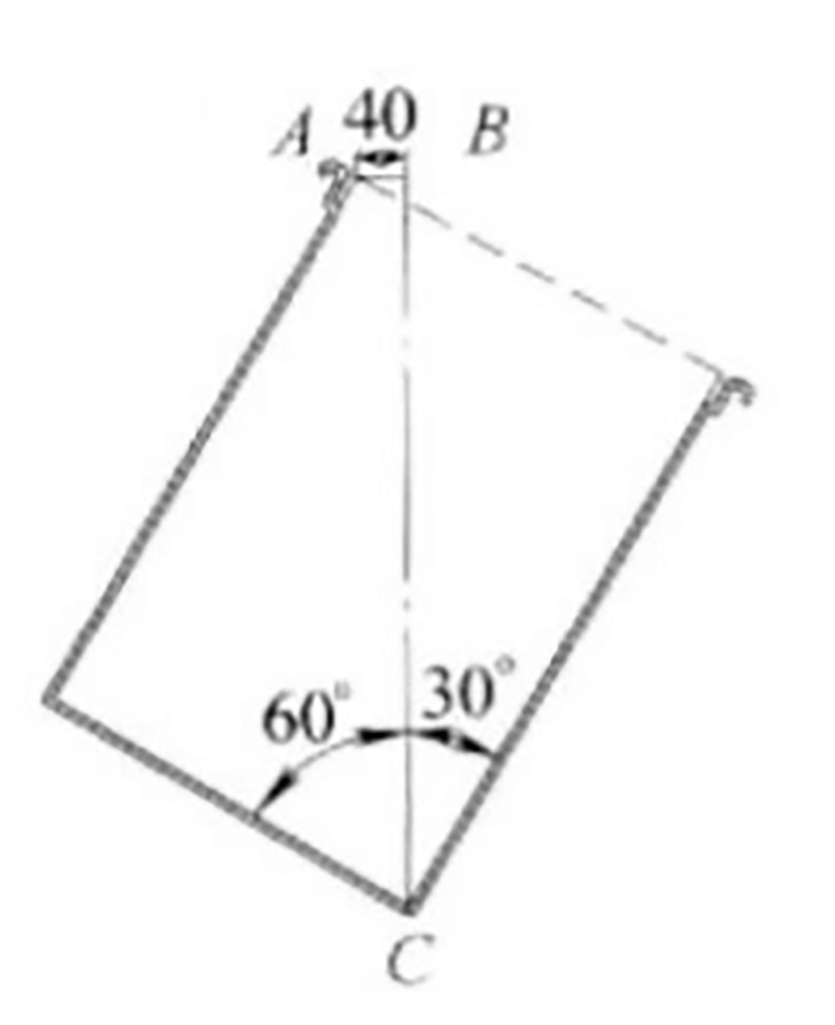
In plan view, the U-shaped part is considered a rectangle (refer to Figure 5). The point A has been shifted 40 mm (equivalent to half the thickness of the press brake machine panel which is 80 mm) to the point B. The diagonal line between points B and C divides the right angle into two parts, 30° and 60° respectively.
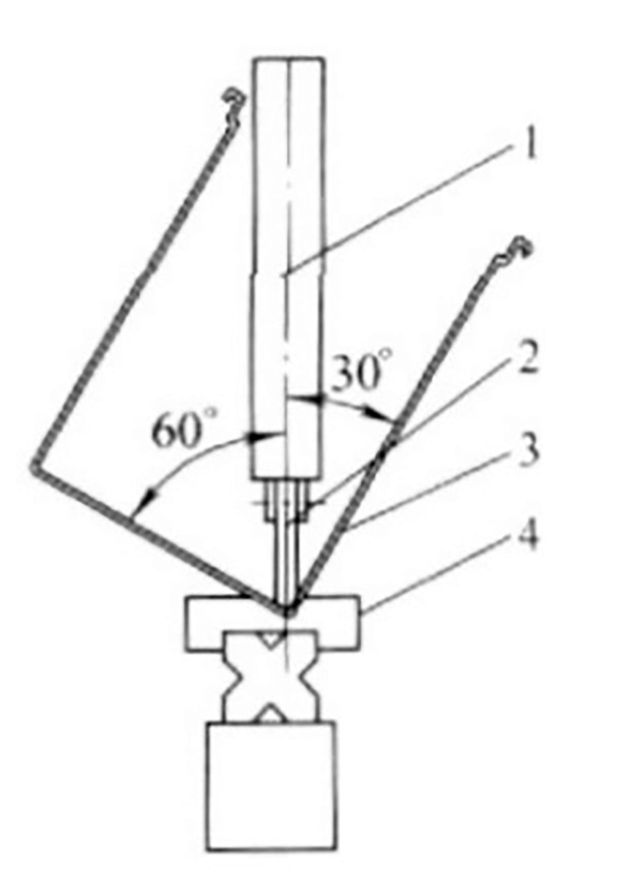
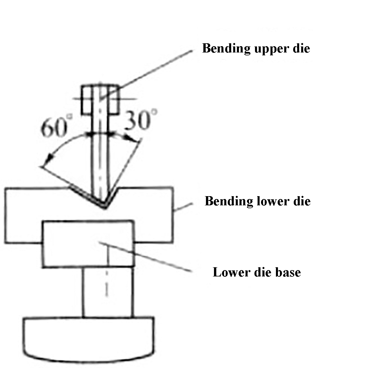
Based on these findings, we designed the bending upper and lower die as shown in Figure 6. The long side of the U-shaped part now avoids the press brake machine panel, thereby expanding the processing range of the press brake machine.
Fig. 5 The plane figure
Fig. 6 The bending upper and lower die
4. Bending die improvement
To resolve the interference problems between the parts and the press brake machine, we made improvements for two different press brake machines.
The first improvement was made to the ordinary press brake machine. The process involved using the original bending die as a reference, fixing the lower die as a base, and then securing the newly designed asymmetric lower die on it. Finally, the upper die was directly replaced, as shown in Figure 7.
Fig. 7 Improvement on the ordinary press brake machine
The second improvement was made to the CNC press brake machine. The process involved adding an adjustable lower die holder that is connected to the base of the press brake machine. The upper die was then directly replaced, as shown in Figure 8.
Fig. 8 Improvement on the CNC press brake machine
The adjustment process for this asymmetrical die is different from the symmetrical adjustment process for the ordinary die.
For the ordinary die, only the thickness of the bent parts needs to be adjusted using the tip points of the upper and lower dies as the reference.
However, for the asymmetrical die, the spacing between the upper and lower dies should be used as the adjustment standard instead of aligning the tip points of the upper and lower dies.
The adjustment process requires first equalizing the spacing between the upper and lower dies on both sides, and then adjusting to the thickness of the bent parts.
This modification to the original bending die offers lower manufacturing costs, a shorter production cycle, and easier operation, resulting in twice the outcome with half the effort.
5. Conclusion
With the improvement of the bending tool, the interference problem of U-shaped parts during the bending process has been resolved and the processing capacity of the press brake machine has been increased.
The operation is straightforward and user-friendly.
For different U-shaped parts, the left and right angles of the bending tool can also be rearranged to solve the interference problem, making it highly valuable for wider use and promotion.