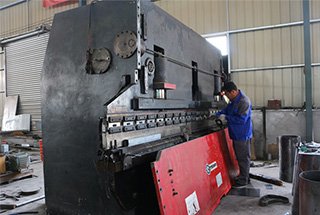
Have you ever encountered bending problems with your press brake? As an experienced mechanical engineer, I’ve seen my fair share of issues that can arise during the bending process. In this blog post, we’ll dive into the most common press brake bending problems and explore practical solutions to help you troubleshoot and optimize your bending operations. Whether you’re a seasoned operator or new to the field, this article will provide valuable insights to enhance your press brake performance.
All personnel servicing any part of the press brake must follow safe work practices:
Ensure that all other personnel are clear of the die area(point of operation)while the press brake is being serviced.
Follow in-plant machine lockout procedures to prevent press brake operation during service or troubleshooting.
Post equipment maintenance warning signs.
Utilize proper personal protective equipment as required by regulatory requirements.
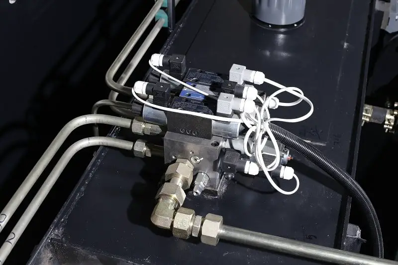
Service personnel may require basic diagnostic tools,such as an electrical multimeter for assessing electrical control problems and a pressure gauge for assessing hydraulic problems.
Service personnel using manual overrides on the hydraulic directional valves should proceed with extreme caution to prevent personal injury or damage to the dies,limit switches or hydraulic cylinders,due to overtravel.
1. Hydraulic pump drive motor will not start
Cause
Solution
Shop electrical supply disconnect switch is OFF.
Turn disconnect switch ON.
Shop electrical supply disconnect switches OFF.
Turn disconnect switch ON.
Loose wire connections in control circuit wiring.
Check for electrical control wiring continuity usinga multimeter and control schematic. Repair as required.
Control circuit fuse FU1 is blown.
Check for possible cause. Remedy cause and replace fuse.
Check for electrical control wiring continuity using a multimeter and control schematic. Repair as required.
Press brake main disconnect switch is OFF.
2. Hydraulic pump drive motor is running but press ram will notcycle
Cause
Solution
Ram control is disabled.(RAM ACTIVElight is flashing.)
Control setting is not the mode beingused. (Hand or foot light is flashing.)
Change control mode to desired setting.
Operational CNC systems interface is incompatible with existing electricalcontrol.
Select calibration, run or third party control mode.
Ram(Y-axis)is uncalibrated.
Neither calibration, run, nor third party control mode are selected.
Backgauge (X-axis) is uncalibrated.
Calibrate backgauge.
ETS system parameter configuration is incorrect.
Contact CNC system dealer/manufacturer.
Consult factory service for procedures in re-setting system configuration.
Hydraulic relief valve is stuck in open position.
Motor rotation is incorrect.
Loose connection/broken wire in operator control pedestal cable or defectiveelectrical contact blocks.
Check for electrical continuity from the footswitch through to the DOWN solenoids. Repair asappropriate.
Check phase sequence at main supply voltage connection to disconnect switch. Ensure sequenceis:1-2-3(red-black-white)。
Defective ram down overrun limit switchor loose/broken electrical connection.
Try to cycle the press ram down using hydraulic valve manual override controls. If no ram motionoccurs, remove relief valve cartridge and inspectthe O-rings and sliding spools for defects orobstructions.
Hydraulic relief valve is stuck in OPENposition.
Loose connection/broken wire in operator control pedestal cable or defective electrical contact blocks.
3. Press ram will cycle down in slow speed only
Cause
Solution
Speed change position is not set correctly.
Optimum setting for speed change is at punchcontact of part being formed.
High volume valve DOWN solenoid is defective.
Check electrical continuity to and at the solenoid. Repair as appropriate.
4. Ram hesitates / stops at speed change point or part contactpoint
Cause
Solution
High pressure relief valve is not maintaining preset relief pressure setting.
Press ram is free falling faster than thesystem can deliver oil to the hydraulic cylinders.
High pressure relief valve is notmaintaining preset relief pressure setting.
Remove the high pressure relief cartridge assembly from the manifold block and inspect the O-rings for damage. Check the center sliding spool to confirm valvefunctionality. Clean with solvent and compressed air to remove any foreign particles. Re-install andtest valve.
5. Press ram will not return to the program up-limit
Cause
Solution
Control mode is set to JOG.
Check for electrical continuity from the operator control pedestal through to the up solenoids. Repair as appropriate.
Loose connection/broken wire in operator control pedestal cable or defective electrical contact block.
Check for electrical continuity from the operator control pedestal through to the up solenoids. Repair as appropriate.
The ram up-limit switch is stuck or damaged in activated position.
Check limit switch mechanical functionality and electrical continuity. Repair as appropriate.
6. Press ram does not stop at bend point
Cause
Solution
Hydraulic directional valve malfunction.
Manually activate the overrides to check pilot valve mechanical functionality. Make sure there is no obstruction of the pilot spool or the valve spool centering springs.
7. Ram stops and/or reverses before developing full tonnage orcompleting the bend
Cause
Solution
Program bend point setting is incorrect.
Check tonnage display and adjust for higher tonnage.
Excessive off center load is causing torsion safety limit switch activation.
Move part being formed closer to center on the press bed.
Check program bend point to see if the press ram reaches the recorded position.
Move part being formed closer to center on thepress bed.
Tonnage control is set too low to complete the bend.
Slow speed change position setting is incorrect.
8. Press tonnage display shows full tonnage but the press failsto complete the bend
Cause
Solution
Part’s material properties are incompatiblewith the press brake and die configuration.
Part’s material properties are incompatible with the press brake and die configuration.
9. Backgauge will not advance to the next flange length step
Cause
Solution
Confirm backgauge program steps reflect the job requirement.
Verify or modify backgauge step program dimension.
Backgauge position dimension per step isnot programmed.
Backgauge position dimension per step is not programmed.
STOP pushbutton is detented OFF.
Reset backgauge STOP pushbutton to ON (1/4turn clockwise)。
10. Hydraulic system is overheating
Cause
Solution
Test the pump flow delivery and pressure at a hydraulic service center. If such facilities are not convenient, the high-pressure cartridge “P2” can be removed and examined for mechanical damage and wear. Replace the cartridge or the complete pump, as required.
Test the pump flow delivery and pressure at a hydraulic service center. If such facilities are not convenient, the high pressure cartridge “P2” can be removed and examined for mechanical damageand wear. Replace the cartridge or the complete pump, as required.
Ensure the press brake speed change point is above the material to be formed and the tonnage indicator is registering within the rated tonnage
Operator is continuously attempting to form parts over the capacity of the press brake.
Hydraulic system high pressure relief valve is relieving prematurely.
The coupling element between the electric motor and hydraulic pump is worn or disintegrated.
Remove the high pressure relief cartridge assembly from the manifold block and examine O-rings for damage. Push the center sliding spool to confirm valve functionality. Clean with solvent and compressed air to remove any foreign particles. Re-install then test valve.
High pressure pump cartridge is defective or worn, resulting in loss of flow andpressure.
Remove the high pressure relief cartridge assembly from the manifold block and examine O-rings for damage. Push the center sliding spool to confirm valve functionality. Clean with solvent and compressed air to remove any foreign particles. Re-install then test valve.
Inspect and replace as required.
11. Hydraulic pump is noisy
Cause
Solution
Hydraulic fluid level is low.
Check fluid level when press ram is in up position.If required, add fluid until visible in sight gauge.
Pump inlet suction strainer is plugged or obstructed.
Check fluid condition. Replace hydraulic strainer,fluid and hydraulic filter as required.
Hydraulic inlet piping or connections are loose, causing pump to ingest air.
Check shaft seal for wear or damage. Replace if required.
Check piping connections, O-ring at pump to inlet flange, and tighten inlet flange bolts.
Check shaft seal for wear or damage. Replace ifrequired.
12. Operating modes will not toggle to next setting
Cause
Solution
EDIT selector switch is set to LOCK.
Verify written job operating procedure and modifyoperating mode for compliance.
13. CNC gauging is inoperative / malfunctioning
Cause
Solution
Incorrect CNC gauging interface
Verify interface documentation and installation.Contact factory service to confirm press brakeinterface requirements.
14. The main motor of the press brake cannot be started
Causes:
The start circuit of the main motor can malfunction due to various factors, including failure to release the emergency stop button, loose cable connections, or an absence of 24V control power.
Furthermore, components related to the main motor’s start system, such as thermal relays, circuit breakers, and AC contactors, may malfunction or become damaged, leading to a failure of the start circuit.
Power problems;
Solutions:
Check whether the emergency stop the main motor’s start the circuit is not released, loose wiring, 24V control power;
To determine the cause of the main motor’s start circuit failure, it is necessary to inspect the components of the starting circuit for overload protection. If present, it is important to analyze the reasons for the overload and check if the components have been damaged.
Check whether the three-phase power is normal;
15. The press brake ram cannot be quickly down
Causes:
The ram rail tuning too tight;
The backgauge axis is not in place;
The ram is not at the top dead center position;
Footswitch signals did not enter the module;
The malfunction of the proportional servo valve;
Solutions:
Check whether the ram rail is appropriate;
To troubleshoot the issue, it is necessary to check if there is a cursor for the actual position of the X-axis on the controller, or to verify if the backgauge programming value and the actual value match in the manual interface.
On the controller, the state of the Y-axis should be set to “1”. If it is set to “6”, it is necessary to check the actual coordinates of the Y-axis. The value should be less than the difference between the Y-axis and its return position.
According to electrical schematics, check whether the input signals of the footswitch are normal;
Check whether the proportional servo valve feedback is normal;
16. The press brake ram cannot bend or bend speed is very slow
Causes:
The ram is not at the speed conversion point;
The set of the parameters of Y-axis bending is not good;
The pressure is not enough, such as programming, machine tool parameter settings, hydraulic;
Solutions:
Check whether the Y-axis state from “2” to “3”, Y-axis actual value should be greater than the speed conversion point value, if not need to adjust the parameters of the fast forward part;
Re-adjust part of the parameters the Y-axis bending;
To further diagnose the issue, it is important to check if the programming operation is incorrect, or if the parameter settings are wrong, or if there are hydraulic problems. To do so, you can use a pressure gauge and multimeter to detect the main pressure and proportional pressure valve signal. Then, check if the proportional pressure valve and main valve are stuck, inspect the filter and oil, and finally, check the pump and its coupling.
Cannot return without load, maybe the parameter’s problem or hydraulic failure;
Can not return during bending, the workpiece angle does not meet the set value;
Can not return during bending, the workpiece angle has exceeded the set value;
Solutions:
To resolve the Y-axis issues, it is important to debug the parameters of the Y-axis and bending parameters based on actual conditions. If the gain is too small, the ram may not bend properly or at all, and if it is too large, the ram may shake. The parameters should be adjusted so that the ram does not shake or has a slightly higher gain.
Additionally, the bias settings for the left and right valve may also need to be adjusted during the diagnostic procedure. If the Y-axis is too small, it may not be able to reach its position, and if it is too large, it may not be able to unload. In case of hydraulic failure, it is necessary to check the main pressure and verify if the PV valve S5 has been placed in the power position.
It is possible that the gain setting of the Y-axis parameter is too small, which can be properly increased. Alternatively, the pressure may not be sufficient, and it is necessary to analyze the reason for the lack of pressure. This could be due to programming or hydraulic factors.
The programming factors include mold selection, plate thickness, material, workpiece length, bending method, etc. On the other hand, hydraulic factors include hydraulic pump leakage, contamination or damage to the proportional pressure valve, a blocked filter, or contaminated oil.
Mainly the programming and operating reasons, check the program and the workpiece;
18. The ram moving is not good
Causes:
The tightness of the ram rail is not appropriate;
Ram lock nut loose;
Machine parameters need to be adjusted;
The gain, zero points on the amplifier of the proportional servo valve need to adjust;
The pressure of the back pressure valve may be incorrect or imbalanced between the two sides. If the back pressure setting is too small, the ram may slowly decline and shake during operation. An imbalance in the back pressure between the two sides can cause the ram to twist during operation.
Solutions:
Re-adjust the guide clearance;
Re-locking, if the lock nut and screw are too loose, need to be replaced;
If there is a reference curve, should be adjusted according to the reference curve;
Only BOSCH, REXROTH valve can be adjustable, but need to be cautious;
Use pressure gauges to adjust the pressure of the back pressure valve, and make the two sides consistent;
19. The main motor automatically stops, heat relay, circuit breaker protection
Causes:
The proportional pressure valve, the main valve was stuck, the machine has been in the state of pressure-adding;
The filter plug blocked, the oil movement is not smooth, the pump pressure has been high;
The use of oil for too long has been contaminated;
Poor oil quality;
Circuit breakers, thermal succession problems, fail to reach the rated current;
The failure of pressure output controlled by the system, and send the wrong signal, so that the proportional pressure valve worked all the time;
Solutions:
Cleaning the proportional pressure valve, the main valve;
Replace the filter and check the pollution degree of the oil;
I3, immediately replace the oil filter;
Replaced with the recommended oil;
Replace the circuit breaker, overheat switch;
Check the system output;
20. The hydraulic valve is stuck
Causes:
The use of oil for too long has been contaminated;
Poor quality of oil;
The rubber skin at the mouth of the oil tank aging;
Solutions:
Replace oil on time;
Replace the recommended oil;
Replace oil-resistant rubber sheet;
21. Press brake cylinder decline
Causes:
Back pressure valve, the lift valve is dirty or damaged;
Back pressure is small;
Glyd lap strain, wear;
Cylinder inner wall damaged;
If the ram stopped at any position and slowly decline, if 5 minutes down less than 0.50mm, then it’s normal, this phenomenon is mainly caused by hydraulic oil characteristics;
Solutions:
Cleaning back pressure valve, lift the valve, if damage replaced;
Re-adjust the pressure on the back pressure valve according to the standard;
Replace the Glyd ring, and check the strain and wear causes of Gglyd ring,;
Generally due to oil pollution, replace the cylinder, sealing ring;
Back pressure on both sides is inconsistent, back pressure setting may be high;
Solutions:
Adjust the back pressure to the specified value, to maintain consistency;
23. The ram is waiting too long at the speed transition point
Causes:
The tank suction port leak;
Filling valve failure, such as the poor installation leads to the stuck of the valve core, or spring tension is not enough;
The set of Y-axis parameters is not good;
Solutions:
Check the sealing of the rubber sheet, re-install the cover here;
Check the filling valve installation, check the running of the valve core, check the spring tension;
Adjust the Y-axis parameters;
24. The length and bending angles of the workpiece changes too much
Causes:
Machine inertia parameter setting is not appropriate;
sheet material;
Solutions:
Re-adjust the machine inertia parameters;
Check the sheet material;
25. When the workpiece has a multi-way bend, the size of cumulative error has too large errors
Causes:
The workpiece has too much bending steps, resulting in a large accumulation error;
Unreasonable bending order;
Solutions:
Fine adjust the accuracy of each bend so that the angle as far as possible in the negative difference, the size as accurate as possible;
Adjust the bending sequence if possible;
26. The automatically calculated pressure from the press brake controller is greater than the die impedance
Causes:
The selection of lower die during programming mode is unreasonable;
The set of mold impedance is not correct;
The programming bending method is chosen wrong;
The machine constant parameters are modified, such as material parameters, unit selection;
Solutions:
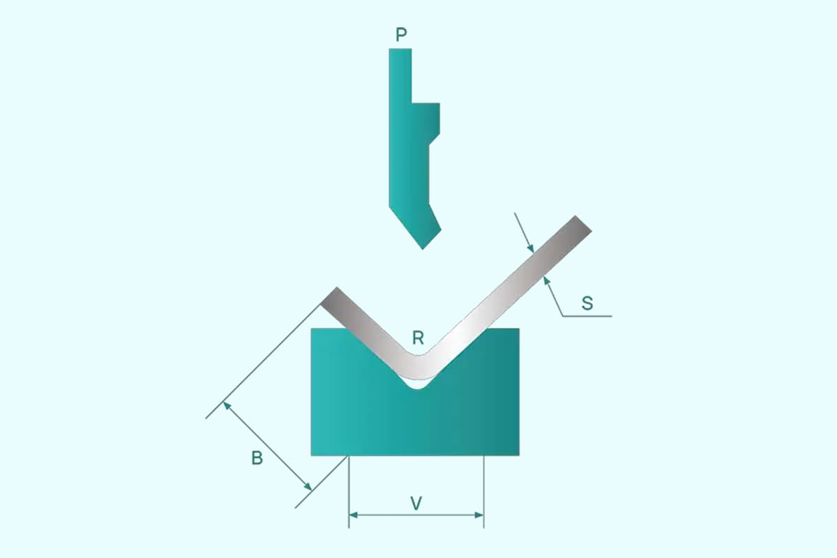
Should select the press brake toolings according to the relationship between the plate thickness and V slot width of the lower die;
The correct set of mold impedance;
Check the program;
Check the machine tool constant parameters;
27. When programming large circular arc bending, the system is calculated to be slow or dead
Causes:
The programmed value of the X value exceeds the maximum value of the X-axis in the parameter;
Solutions:
Check the program;
28. The press brake hydraulic oil temperature is too high
Causes:
Hydraulic failure, such as the filter is blocked, oil pollution, deterioration, etc;
Long hours work under high pressure;
Solutions:
Check the filter, oil, if necessary, replacement;
Check the reasons for long hours of high-pressure work, is the actual needs, or other reasons;
29. The angles of the fabricated workpiece are not accurate
Causes:
If the error is very large, it may be programming error, ram connection loosening, grating ruler failure;
if small error, you can correct the parameters in the controller, after the amendment can work stably, then is it normal;
Unstable angle, often change, may be caused by the ram loose, grating ruler failure, metal materials;
Solutions:
To troubleshoot the issue, it is important to review the running procedures and focus on checking if the mold, material, thickness, workpiece length, and bending mode in the procedures match the actual operation. Additionally, it is important to inspect if the ram connection is secure and if the grating connection is firm.
Small errors during the operation may be caused by a variety of factors, such as differences between the programmed material thickness and the actual thickness used, material uniformity, mold wear, and operator-related reasons.
To determine the cause of the issue, it is necessary to check the accuracy of the Y-axis re-positioning. Additionally, inspect if the ram connection and grating connection are normal. If they are normal, the issue may be caused by the plate material.
30. The fabricated workpiece size is not accurate
Causes:
Frequent changes in the size of instability can be caused by factors such as the press brake machine’s power supply, servo drive, servo motor encoder and related cables, systems, screw mechanical connection, and timing belt (wheel).
Stable deviations in size are most often caused by the parallelism and straightness of the backgauge beam, and the parallelism and vertical degree of the back stopper.
When positioning using the bending edge, if the bend angle is greater than 90 degrees, it can result in a small positioning distance.
Solutions:
It is important to check the accuracy of the backgauge axis repeat positioning, which should generally be less than 0.02mm. If there is a significant deviation, it is necessary to identify the possible factors and address them. If the issue is caused by the servo drive, servo motor encoder, or controller, it is best to seek assistance from the press brake manufacturer.
To resolve the issue, it is important to first check the parallelism and straightness of the beam, and then check the parallelism and vertical degree of the back stopper.
If positioning using the bending edge, it is recommended to ensure that the bend angle does not exceed 90 degrees.
31. The workpiece deforms at the bending position after bending
Causes:
The cause of deformation is primarily due to the fast bending speed, resulting in the hand not keeping up with the bending deformation of the workpiece.
Solutions:
To resolve the issue, it is necessary to reduce the bending speed and ensure that the hands move in tandem with the workpiece.
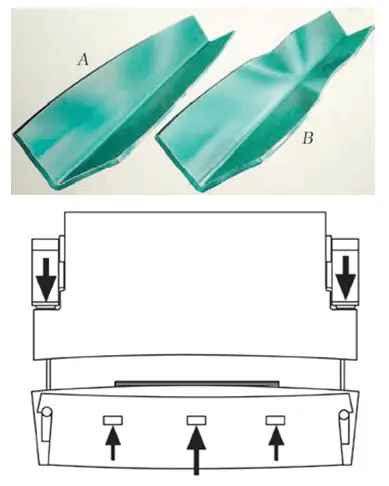
32. The bending angle of the long workpiece is not consistent
Causes:
The issue may be caused by inconsistencies in the material thickness, with one end being thick and the other end being thin.
The problem may be caused by an inconsistent height of the punch, with one end being higher than the other.
The issue may be caused by an uneven middle block.
Solutions:
Please provide feedback to the Laser Cutting department and ensure that proper attention is given to the selection of materials. Additionally, replace the press brake punch and adjust the middle block as necessary.
33. Sometimes the workpiece will be deformed during Z-bending
Causes:
During the bending process, the rear end of the workpiece rises along the curve and makes contact with the back finger, causing it to become stuck. As a result, the workpiece becomes deformed after the bending process.
Solutions:
Adopt the rear-pulling function of the back stopper.
34. The edge of the square hole in the middle of the sheet metal is very close to the bending line which makes the workpiece can’t be bent completely.
Causes:
The distance from the edge of the workpiece to the bending line is less than half the size of the V-opening in the die, making it impossible to bend.
Solutions:
Grind the material to the bending line.
Press the bending line first and then bend it.
35. There is a hole on the workpiece and it is very close to the bending line. The hole will be deformed if bend directly.
Solutions:
Press the line first and then bend.
Cut out one line at the bending position with a laser cutter so as to avoid material pulling.
If the production involves small batches and requires good finishing, it is recommended to use a laser cutting machine for hole-making and bending. Finally, complete the entire expansion process.
36. The small bending size makes it hard for positioning and the punch is easily press the back finger
Causes:
The size of the bend is within the range of the distance from the centerline of the V-shaped opening in the die to the edge of the workpiece, making it difficult to position if the die is installed in its normal orientation. If it is installed in reverse, the punch will press against the back finger.
Solutions:
To avoid the punch, install the die in reverse and place a gasket in front of the back stopper, causing it to recede.
If the size of the other end is accurate, it is possible to perform positioning at that location. It is important to remember to install the die in the reverse position.
37. The bending flange is not straight and the size is unstable
Causes:
Press lines and pre-bending were not taken into consideration during the design process.
The press force is insufficient.
The angular wear on the convex and concave dies is asymmetrical or the bending force is uneven.
When bending with elastic pressure and positioning with holes, the exterior of the elbow may be pulled due to friction between the concave die surface and the exterior surface of the parts, causing deformation of the positioning holes.
Solutions:
Adopt shape bending
Increase the pressure of the ejector plate
To prevent sliding of the parts during bending, add some hard spots or grain to the ejector plate to increase the friction force.
41. The curved surface is been squeezed thinner
Causes:
The round angle of the concave die is too small
The gap between the convex and concave dies is too small
Solutions:
Increase the radius of the concave die
Correct the gap between convex and concave dies
42. The end face of the workpiece is bulging or uneven
Causes:
During bending, the outer surface of the material is pulled in a circular direction, causing contraction deformation, while the inner surface is pressed in a circular direction, resulting in elongation deformation. This causes the flexural end surface to bulge along the bending direction.
Solutions:
The punch shall be under sufficient pressure in the final stage of stamping
Make the concave die radius corresponding to the outside corner of the parts
Additional process improvement
43. The bottom of the concave piece is uneven
Causes:
The material itself is uneven
The contact area between the top plate and material is small or the material ejection force is insufficient
No need for the ejection device in the concave die
Solutions:
Leveling materials
Adjust the ejection device to increase ejector force
Add ejector device or calibration
Add reshaping procedure
44. Axis dislocation of two holes opposed to each other after bending
Causes:
The material bounces back and changes the bending angle so that the centerline is misaligned.
Solutions:
Add calibration procedure
Improve bending die structure to reduce material resilience
45. The precision of the hole position cannot be guaranteed after bending
Add calibration procedure or improve bending die forming structure
Change technique methods or add technique positioning process
46. The curved line is not parallel to the center of the two holes
Causes:
When the bending height is less than the minimum bending limit height, the bending part will expand.
Solutions:
Increase the height of the bending parts
Improve the bending technique
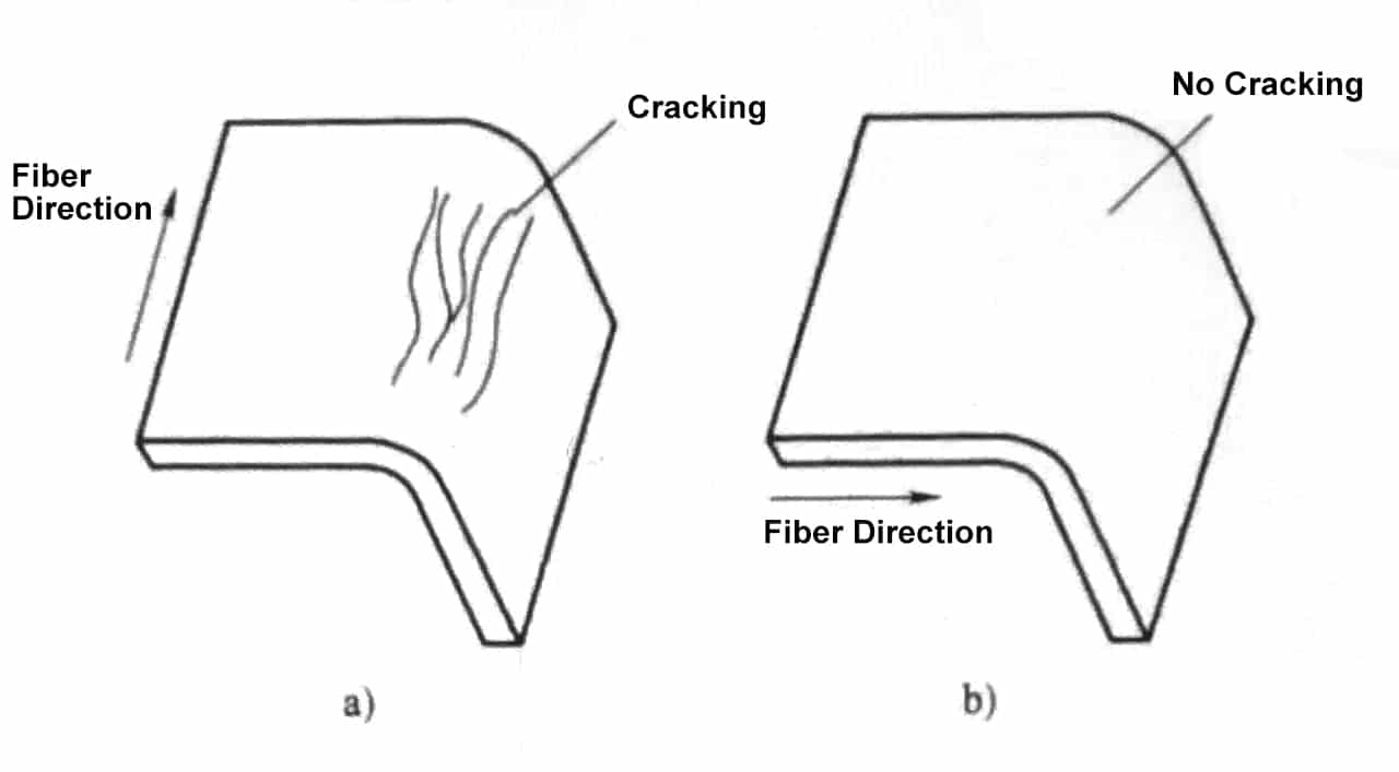
47. The bent part has a bow deflection in the width direction
Causes:
Torsion and deflection are produced because of the inconsistency of the drawing depth and shrinkage in the width direction of the component.
Solutions:
Increase bending pressure
Add calibration procedure
Ensure that the material grain direction and bending direction have a certain angle
48. The parts with cut notch bend down
Causes:
The cut notch opens the two straight edges to the left and right, causing a deflection at the bottom of the piece.
Solutions:
Improve component structure
The amount of technological bend allowance is increased at the incision to make the incision connected and then cut off after bending
49. The workpiece deformed after bending
Causes:
The deformation is mainly due to the speed of the bending machine, and the hand did not keep up with the speed of the machine.
Solutions:
Reduce the speed of the bending machine, the hand-held workpiece has the same speed as the operation of the machine.
50. For the longer workpiece, there will be a big angle and a small one at two ends
Causes:
Material thickness is inconsistent, one end thick one end thin.
Mold wear uneven, different height at both ends.
The middle block is not balanced, not at the same level.
Solutions:
Feedback to the laser or NCT, let it pay attention to the material selection.
Change the punch die
Adjust the middle block.
51. When bending Z shape by CNC bending machine, some parts will be deformed
Causes:
This is mainly due to the workpiece bending up movement, hit the back stopper and was squeezed which lead to the deformation.
Solutions:
Pull-back the back gauge.
52. Bending size is small, bad positioning, the mold is easy to press the back gauge
Causes:
The bottom die cannot be positioned during the distance from the V centerline to the edge of the die.
Solutions:
Install the mold in another way around. Add one gasket (no more than 3t) before the back gauge, so that the back gauge can avoid the upper mold.
If the other end size ≧ 3 can also make the other end stay and install the lower mold in another way around.
53. A too-large gap between the ram and guide rail, make an abnormal sound.
Causes:
This type of malfunction is due to the long use of rails, increased gap caused by wear.
Solutions:
It is necessary to check the degree of wear of the guide plate, to determine whether to replace the rail plate depending on the degree of wear, re-adjust the gap to meet the requirements.
54. Transmission failure of the back gauge.
Causes:
The back-gauge transmission fails because the drive shaft is disengaged from the timing belt of the timing pulley or the belt is slipping.
Solutions:
This malfunction requires reassembling the chain and timing belt, then check the electrical section.
55. Parallel misalignment too much between the cross-beam guide rail of the back gauge and the mold centerline.
Solutions:
Such failure needs to release the “X” axis synchronous belt, re-adjust to the parallelism tolerance range, reinstall the synchronous belt.
56. Cylinder and ram connection loosening, causing the bending angle not accurate or the machine cannot find the reference point.
Solutions:
This type of fault requires re-checking the tightened ram and the cylinder connection nut.
Check whether the proportional relief valve solenoid coil is power on. If the electromagnetic coil voltage meets the requirements. For the above reasons, please check the relevant electrical parts.
Check whether the cartridge valve is stuck or the main spool is stuck as well as damp hole clogging. If this is the reason, please remove the relief valve and clean it.
three-phase power phase modulation, resulting in motor reversal.
58. Ram speed turns to slow from fast, pause too long.
Solutions:
Check whether the tank oil surface is too low, the filling mouth was not flooded. When fast forward the cylinder chamber filled with liquid and air which leads to insufficient filling. For the above reasons, the tank oil can be added to the filling tank 5mm above the filling mouth until it been completely flooded.
Check whether the fast forward speed is too fast, causing insufficient filling. For the reasons described above, you can reduce the fast forward speed by modifying the system parameters.
Check whether the filling valve is completely open if it is because of oil pollution so that the valve spool activity is not flexible and stuck issue leads to insufficient oil filling. Need to clean the filling valve and re-install it, make the spool flexible.
Check whether the reversing valve, which controls the oil circuit, is working properly. If so, it causes the filling valve is not closed, so that the upper chamber and the tank filling port connected, cannot build pressure. The reason why the valve does not work properly is that it is not energized or stuck.
Check whether the filling valve is stuck, if so, please clean the filling valve, reinstalled, so that the spool flexible.
60. The ram return speed is too slow.
Causes:
The malfunction like high return pressure is mainly because the filling valve is not open. This phenomenon is just contrary to the logical of the above malfunction 3.
Solutions:
This can be handled by referring to the solution of the malfunction 3.
61. After starting the pump of the CNC bending machine, low voltage disconnect switches.
Solutions:
The following checks are required for such failures:
Check the lack of power supply phenomenon.
Check whether the high-pressure filter blockage, resulting in pump motor current is too large.
Check whether the low-voltage switch is set too small.
62. After starting the CNC press brakes, the reference point cannot be found during the return.
Solutions:
The reading head connection parts of the grating ruler may become loose, causing the reading head to not align with the reference point on the grating ruler during the return stroke. In this case, the cylinder has exceeded its stroke and the pump is operating under overload. To resolve this issue, press the red stop button on the CNC system to halt the reference point. Reconnect the connector to fix the grating ruler, switch to manual mode, and manually lower the ram until it aligns with the lower die. Then return to the reference point and rectify the problem.
If the operator failed to properly shut down the press brake machine after the last operation and did not stop the ram at the top dead center position before powering off the CNC press brake, the ram may be in the overlap position of the upper and lower mold during the next startup. This will result in the system being unable to find the reference point during the reference point operation.
To resolve this issue, switch the system to manual mode and manually adjust the ram to the overlap position of the upper and lower mold. Then switch to semi-automatic or automatic mode and re-locate the reference point.
63. For DNC60 or DNC600 CNC bending machine, the CNC system did not display, gray-white programming key indicator light flashing.
Causes:
This malfunction is typically caused by the controller operator not promptly and thoroughly clearing unused product programs during the product programming process and instead directly modifying the program of the previous product.
Repeated occurrences of this behavior can lead to the system’s buffer memory becoming filled with programs, causing the system program to not function properly.
Solutions:
To resolve the issue, first disconnect the main motor power. Then, simultaneously press the “+ +” and “- -” keys on the keyboard. Finally, turn the power back on to return the system to its initial state.
Next, clear the project by inputting “1” to indicate the item to be cleared. After entering the password “817”, press the enter key to confirm. The screen will display a prompt that the operation has been executed. At this point, the necessary steps to clear the project have been completed.
64. “count is not accurate” of CNC bending machine grating ruler causes bending angle error.
Causes:
This malfunction primarily results from the cumulative increase of repositioning accuracy errors in the “Y1” and “Y2” axes, leading to an increase in the angle error of the workpiece after bending. This increase in angular error builds upon previous errors and is mainly caused by the grating ruler feedback signal losing pulses.
Solutions:
To resolve this issue, remove the grating ruler and thoroughly clean it. Implement measures to reduce dust and vibrations. Re-design and re-install the grating ruler to ensure a reasonable level of installation. If the grating ruler is damaged, it should be returned to the manufacturer for repair or replacement.
65. After the product is programmed, the safe distance alarmed for the back gauge “X” axis and “R” axis.
Causes:
This type of malfunction occurs primarily because the settings for the safe distance between the upper and lower molds, as well as the limit positions for the X and R axes, conflict with the programmed positions. To ensure safety, the system will trigger an alarm and prevent operation if these settings are incorrect.
Solutions:
To resolve the issue, reprogram the product or modify the product parameters or mold settings so that they meet the requirements. This will remove the alarm and allow for operation.
66. Back gauge X-axis and R-axis, an error occurs in the drive motor
Solutions:
To address this type of failure, first open the electric box of the CNC bending machine. Check the driver display for the alarm code and determine the cause of the alarm by referencing the user manual and the prompt alarm code.
Two common alarms are:
Alarm 16, indicating a drive motor overload. Check the flexibility, resistance, and mechanical limit of the X-axis and Y-axis drives. If necessary, resolve any mechanical issues.
Alarm 22, indicating an encoder feedback signal alarm. This may be caused by poor contact at the “joint”, unsoldering or disconnection, or signal interference. Check each issue one by one.
67. Y1, Y2 computer display location does not match the actual location.
Causes:
This type of failure is mainly due to changes in the original reference point of NC bending machine are not accurate.
Solutions:
To reinitialize the reference point.
68. The X, R-axis controller positioning does not match the actual positioning.
Causes:
This type of malfunction is caused by a change in the position of the X-axis and R-axis while the machine is powered off. The computer retains the memory of the location prior to shutdown, leading to a discrepancy between the actual and recorded positions of the X-axis and R-axis.
Solutions:
The position of the X-axis R-axis needs to be reinitialized.
69. Y1 axis and Y2 axis position deviation exceed the allowed synchronization deviation distance, the ram cannot move up and down.
Causes:
This type of failure occurs when the ram is not positioned between the upper and lower mold at the time of shutdown, causing the punch to fall. As a result, the actual positions of the Y1 and Y2 axes exceed their limits.
To resolve the issue, adjust the actual positions of the Y1 and Y2 axes. The controller should display the current position value. Once the adjustment is made, the press brake can be operated normally.
Solutions:
To resolve the issue, increase the data in the controller of the CNC press brake machine by 5mm from its original value. Then switch to manual mode and manually lower the ram. The system will automatically correct the position and return to normal operation.
70. Unequal angle at each end of formed part
Cause
Solution
Variance in metal thickness.
Offset the ram parallel to compensate for anything variance.
Check material thickness at both ends of the part.Offset the ram parallel to compensate for material thickness variance.
Offset the ram parallel to compensate for any tooling variance.
71. Inconsistency in formed parts
Cause
Solution
Press ram, bed and tooling are coated withrust-proofing.
Remove die set, clean all parts with solvent, re-assemble and readjust.
Tooling does not lie flat on press bed cap
Check clearance with feeler gauges. Shim between press bed and tooling, or mechanically straighten as required.
Tooling is worn.
Check clearance with feeler gauges. Shim between press bed and tooling, or mechanically straighten asrequired.
72. Each formed part exhibits a consistent angle from end to end,but there is inconsistency from part to part
Cause
Solution
Press ram is free falling
Check press ram ways assembly adjustment.
Disassemble and inspect for damaged or wornspools landings, spools, springs, or for contaminants.
Disassemble and inspect for damaged or worn-spools landings, spools, springs, or for contaminants.
73. Each formed part exhibits an inconsistent angle from end to end
As the founder of MachineMFG, I have dedicated over a decade of my career to the metalworking industry. My extensive experience has allowed me to become an expert in the fields of sheet metal fabrication, machining, mechanical engineering, and machine tools for metals. I am constantly thinking, reading, and writing about these subjects, constantly striving to stay at the forefront of my field. Let my knowledge and expertise be an asset to your business.
Attention all mechanics and engineering enthusiasts! Have you ever wondered about the ins and outs of operating a press brake machine? In this blog post, we'll dive into the world…
Choosing between an electric and hydraulic press brake can significantly impact your business efficiency and costs. Electric press brakes offer superior energy savings, environmental benefits, and faster operation speeds, while…
Attention all metalworking enthusiasts! Are you tired of guessing the proper tonnage for your press brake? Look no further! In this blog post, we'll dive into the world of press…
In the vast world of manufacturing, one machine stands tall: the press brake. With its ability to bend and shape metal with precision and power, it has become an indispensable…
Is your hydraulic press brake causing more headaches than it should? Ensuring these complex machines run smoothly is vital to avoid costly downtime and repairs. This article covers essential maintenance…
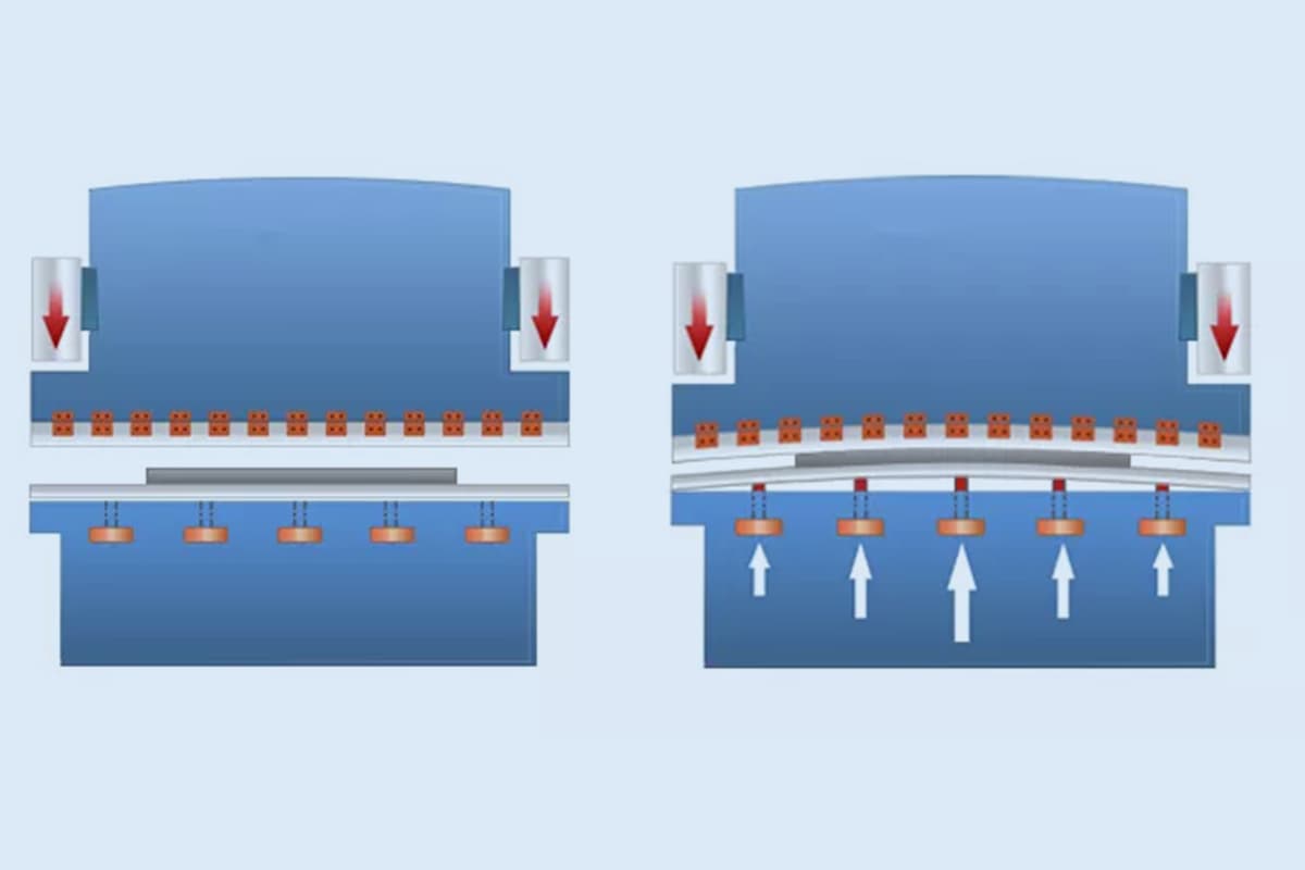
Ever wondered why your metal bends aren't always perfect? The secret lies in press brake crowning, a technique that ensures precision and quality in metal fabrication. This article will reveal…
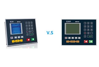
What makes the E21 and E200P press brake controllers distinct, and which one suits your needs? In this article, we compare these two controllers, both from Estun, by analyzing their…
How does a machine achieve high precision and efficiency in metal bending? Discover the secrets behind the Electro-Hydraulic Servo Press Brake. This article delves into the intricate mechanics, setup procedures,…
Have you ever wondered what makes press brake dies so fascinating? In this captivating blog post, we'll delve into the intricate world of these essential tools that shape the metal…