Ever wondered how sheet metal is expertly bent into intricate shapes? This article explores six types of press brake bending processes—folding, wiping, air bending, bottoming, coining, and three-point bending. You’ll learn the unique benefits and limitations of each method, and how they contribute to efficient and precise metal fabrication. From simple bends to complex profiles, these techniques are essential for producing high-quality parts in manufacturing. Dive in to understand how these bending processes can enhance your projects.
Press brakes are capable of accomplishing a lot, but there are still challenges involved in producing top-quality parts. In this discussion, we will explore the different types of bending.
To achieve a reproducible and reliable press brake process, it is necessary to have a combination of the press brake and its tools.
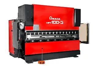
A press brake typically consists of two sturdy C frames that form the sides of the machine, connected on the bottom by a massive table and on the top by a movable upper beam. However, the opposite configuration is also possible.
The bottom tool rests on the table while the top tool attaches to the upper beam. In hydraulic press brakes, which are the majority of machines produced these days, the upper beam moves via two synchronized hydraulic cylinders attached to the C frames.
The capabilities of press brakes are defined by several characteristics, including pressure or tonnage, working length, distance to the backgauge, work height, and stroke. The speed at which the upper beam operates typically ranges from 1 to 15 mm/sec.
Increasingly, press brakes are equipped with multi-axis computer-controlled backgauges and mechanical and optical sensors to make adjustments during the bending process. These sensors measure the bending angle during the bend cycle and transmit data in real-time to machine controls, which adjust process parameters accordingly.
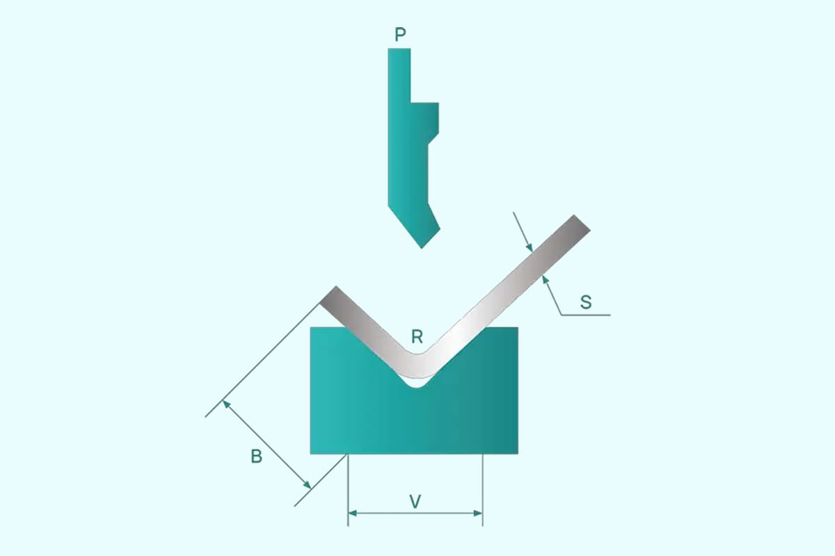
Ultimately, press brake bending is a combination of factors that involve the geometry of the top tool (with the punch angle and punch tip radius being the most important parameters), the geometry of the bottom tool (particularly the width of the V opening, the V angle, and the bending radii of the V opening), and the pressing force and speed of the press brake.
2 Types of Bending
Folding
During the folding process, the longest leg of the sheet is clamped between two clamping beams. Then, the bend beam rises and folds the extending part of the sheet around a bend profile, as shown in Figure 1.
In modern bending machines, the bend beam is capable of forming both upward and downward, which is a significant advantage when creating complex parts with positive and negative bend angles.
The resulting bend angle is determined by the folding angle of the bending beam, the tool geometry, and material properties.
Bending through folding offers a significant advantage in that large sheets can be handled relatively easily, making this technique simple to automate. Additionally, with folding, there is minimal risk of damage to the sheet metal surface.
However, one limiting factor of folding is that the movement of the bend beam requires sufficient space and throughput time.
Wiping
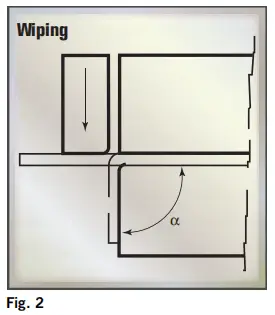
In the wiping process, the sheet is once again clamped between the clamping beams. The tool then bends the protruding part of the sheet around the bend profile by moving up and down, as shown in Figure 2.
Compared to folding, wiping is a faster technique for bending, but it also increases the risk of scratches or other damage to the sheet as the tool moves over the sheet surface. This risk is especially high if the bending involves sharp angles.
Wiping is commonly used for making panel-type products with small profiled edges. With special tools, this technique can be readily accomplished on press brakes.
4 Bending Variations
When it comes to bending, there are four variations: air bending, bottoming, coining, and three-point bending.
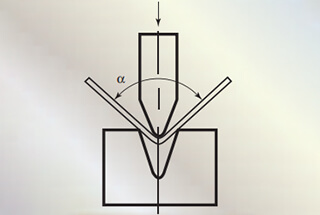
The characteristic of bending is that the sheet is pressed by a top tool into the opening of the bottom tool, as shown in Figure 3.
As a result of the bending process, sheet metal on each side of the bend is lifted, which can cause problems such as sagging and folding, especially with large sheets.
In such cases, folding or wiping is often preferred, although sheet follow supports can also be used with the press brake to alleviate these issues.
When bending involves positive and negative angles, folding offers more flexibility than other techniques.
One of the significant advantages of using press brakes is the increased speed and flexibility they offer.
Air Bending (Partial bending)
Air bending is the most frequently used type of bending thanks to the significant improvements made in new press brakes, which offer better control of sheet metal springback.
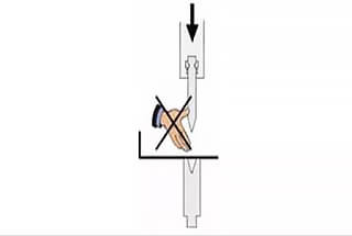
This type of bending is used when there is air between the sheet metal and the die vee. The name “partial bending”‘ comes from the fact that the sheet metal comes into partial contact with the upper and lower tools,i.e. at only three points during the bending procedure.
With air bending, the top tool presses a sheet into the V opening in the bottom tool to a predetermined depth, but without touching the bottom of the tool, as shown in Figure 4.
Air bending is a type of three-point bending, where only the bending radii of the top and bottom tools contact the sheet. The punch radius of the top tool and the V angle of the bottom tool need not be the same. In some cases, a square opening replaces the V opening in the bottom tool, especially with today’s adjustable bottom tools.
The combination of top and bottom tools can be applied universally, allowing for the production of various products and profile shapes with a single combination, simply by adjusting the press stroke depth. In other words, a single combination of tools can be used to bend multiple materials and thicknesses in a range of bend angles, making air bending a highly flexible technique.
This also means that the number of tool changes required can be limited, considerably enhancing productivity.
Air bending has another advantage in that less bend force is required, allowing for smaller and less bulky tools and providing additional design flexibility.
However, one limitation of this technique is that it is less precise than processes where the sheet maintains full contact with the tooling throughout the bending process. The stroke depth must be highly accurate, and variations in sheet thickness and local wear on the tooling can result in unacceptable deviations.
Additionally, variations in material properties can affect the resulting bend angle due to springback.
Air bending requires a certain width for the V opening, which varies according to the sheet thickness. For sheets up to 3 mm thick, the value is 6 times the material thickness, while for sheets over 10 mm thick, the value is 12 times the material thickness. A rule of thumb is V=8S.
Air bending offers an angle accuracy of approximately ±0.5 deg. However, the bend radius is not determined by tool shape, but rather by material elasticity. Typically, the bend radius is between 1S and 2S.
Due to its flexibility and low tonnage requirements, air bending is becoming the preferred forming technique among fabricators. However, variations in sheet thickness, local wear on the top and bottom tools, and material properties can result in deviations in angle accuracy.
Special measures, such as angle-measuring systems, clamps, crowning systems adjustable along the X and Y axes, and wear-resistant tools, can help remedy these quality issues.
Advantages:
Air bending enables the production of a wide range of angles using tools with acute angles. For example, you can use a 30° punch and a 30° die to bend profiles at any angle between 30° and 180°;
Air bending is faster than other types of bending because of the shorter travel of the punch;
Springback is managed by taking the punch tip deeper into the die vee and making a closer angle, instead of increasing the bending force or the dwell;
The necessary bending force is lower than in other bending types thanks to the option of choosing a wider die vee;
There is less marking of the sheet metal from friction with the tools;
The tools and the press suffer less wear;
Air bending enables the use of low-force press brakes. Costs are lower and therefore air bending is an economical type of bending
Disadvantages:
Angle precision with air bending is lower than with other bending types. Tolerance is 3/4 of a degree (45′);
Bending intemal radius is not very precise. Infact the tip produces an ellipse;
As sheet metal does not yield, springback is higher and less predictable than with other bending types. So the tool angle must be selected bearing in mind the need to go a degree or so beyond the angle required.
If there are any holes near the bending line, they will be deformed.
Bottoming
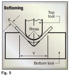
Bottoming is a variation of air bending that involves pressing a sheet against the slopes of the V opening in the bottom tool (see Fig. 5), while allowing air to be trapped between the sheet and the bottom of the V opening.
During bottoming the punch reaches the bottom of the die vee and presses the sheet metal against the sides of the die. This bending type is suitable for precise profiles, since its accuracy and consistency are higher than with air bending.
The higher quality is due to the fact that during bottoming the sheet metal is pressed between the upper and lower tools, and therefore the internal radius is concentrated in the area ofthe bend.
This results in a more accurate radius, the sheet metal yields more and subsequently springback is lower.
The choice of tool is critical for bottoming, as operators have to identify the best angle for both punch and die and the expected spring-back in order to obtain the required profile angle. Punch and die must have the same angle to achieve a good bending result.
In this case, the radius of the punch and the angle of the V-opening are directly linked in bottoming, which means that it does not offer the same flexibility as air bending.
Each bend angle and sheet thickness requires a separate tool set, and the same often applies to different materials due to variations in springback and compensation required in the tool.
For bottoming, the ideal width of the V-opening (U-shaped openings cannot be used) is 6S for sheets up to 3 mm thick, and this increases to 12S for sheets more than 12 mm thick.
Once again, the rule of thumb is: V=8S.
The minimum acceptable bending radius for sheet steel ranges from 0.8S to 2S, although material quality plays a role.
In the case of soft materials such as copper alloys, the radius of the bend angle may be much smaller, with a lower limit of 0.25S being possible.
When it comes to larger bend radii, bottoming requires tonnage that is roughly the same as for air bending.
However, for smaller radii, bottoming requires force that can be up to five times greater than air bending, which can lead to greater accuracy.
The resulting bend angle is entirely determined by the tool, except for springback, which can be corrected.
It is worth noting that bottoming typically results in less springback than air bending.
In theory, bottoming can achieve angle accuracies as precise as ±0.25 degrees.
However, due to the increasing control and adjustment capabilities of press brakes, even on less expensive machines, air bending is becoming the preferred method over bottoming.
Advantages:
Good precision using low force
Good bending repetition in the case of big production series;
Low springback
If there are any holes near the bending line, they are pressed between tools during bottoming, therefore they will not be deformed as happens with air bending;
Tolerance is about half a degree.
Disadvantages:
Angle correction by further downwards movement of the punch is impossible, as the punch is already in the vee bottom;
Bottoming can only be used for bends with angles between 80° and 90°;
Tool sets dedicated to a specific profile are needed;
The appearance of the profile is not as good.
Coining
People may think such a name strange. Actually, coining refers to the process of “punch- ing metal coins”, in which every single piece is identical to every other in shape and size.
For this reason, “coining” can be used in the bending process to indicate a method to obtain very accurate results on a consistent basis.
Coining requires four to five times the force needed for air bending, and so a heavy duty press brake and tools are required.
In coining punch and die must have the same angle as that required by the profile, so, in the case of a 90° bend, a 90° punch and a 90° die have to be used without allowing for springback.
The width of the die vee is smaller for coining than for bottoming and air bending and ideally should be five times the thickness of the sheet metal.
This parameter is to prevent the punchtip from penetrating the sheet metal too much due to the smaller internal radius.
Coining is not recommended for thicknesses over 2mm so as to prevent any damage to the press brake, the tools or the sheet metal.
In coining, the top tool crushes the sheet into the opening of the bottom tool, down to the bottom of the V opening (see Fig. 6).
Coining requires significantly more force than air bending and bottoming, typically 5 to 10 times higher tonnage, and sometimes as much as 25 to 30 times higher. However, it offers the advantage of providing a high level of precision.
Due to the immense pressure applied by the punch tip to the material, permanent deformation occurs throughout the entire cross-section of the sheet, with springback virtually eliminated. Because the punch and V-die angle are identical, the desired bend angle can be easily chosen, and variations in sheet thickness and material properties have little or no impact on coining outcomes.
The high force and permanent deformation imply that the minimum achievable inside radius, starting at 0.4S, is less than with air and bottoming, with the width of the V opening typically requiring about 5S. A wider V opening would necessitate a greater depth to achieve the same bend angle.
In general, coining is more expensive than air bending and bottoming, and is therefore used sporadically, typically only for thin sheets.
Advantages:
Consistent results
Very tight tolerance of an angle (1/4 of a degree)
Pessibility of bending sheet metal with big thickness tolerances
Punch tip penetrate the material with high force and eliminates sheet metal springback:
Posibility of obtaining very small radii (half the thickness of the sheet metal).
Disadvantages:
Press brake and tools wear quickly;
Poor appearance of the sheet metal;
Only for angles up to 90°
Not applicable for metal sheets over 2mm thick.
Three-Point Bending
Three-point bending is a relatively new bending technique that some consider to be a special variation of air bending.
This technique involves using a special die where the bottom tool can be precisely adjusted in height via a servo motor. The sheet bends over the bend radii of the die until it touches the bottom, with the bend angle decreasing as the depth of the die bottom increases.
The height of the bottom die can be determined very precisely (±0.01 mm), with corrections made between the ram and the upper tool using a hydraulic cushion to compensate for deviations in sheet thickness. As a result, the process can achieve bend angles with a precision of less than 0.25 degrees.
The advantages of three-point bending include high flexibility combined with high bending precision. However, obstacles include high costs and a limited range of available tools. Therefore, this technique is currently limited to highly demanding niche markets where the additional costs are outweighed by the stated advantages.
As the founder of MachineMFG, I have dedicated over a decade of my career to the metalworking industry. My extensive experience has allowed me to become an expert in the fields of sheet metal fabrication, machining, mechanical engineering, and machine tools for metals. I am constantly thinking, reading, and writing about these subjects, constantly striving to stay at the forefront of my field. Let my knowledge and expertise be an asset to your business.
Compared to conventional press brakes, CNC press brakes have many advantages in improving working efficiency. Here, we explain these advantages in 6 aspects. Graphical user interface The user interface serves…
Ever wondered how a press brake achieves such precise bends? This article explores the fascinating world of press brake axes, revealing the secrets behind their roles and functions. Learn how…
How can press brake operators ensure their safety while working? This article dives into six crucial tips, from keeping hands clear of dies to managing the backstop finger's position, aimed…
Attention all metalworking professionals! Are you tired of unexpected downtime due to perplexing error codes on your AMADA CNC Press Brake? Look no further! In this blog post, a seasoned…
Attention all mechanics and engineering enthusiasts! Have you ever wondered about the ins and outs of operating a press brake machine? In this blog post, we'll dive into the world…
Choosing between an electric and hydraulic press brake can significantly impact your business efficiency and costs. Electric press brakes offer superior energy savings, environmental benefits, and faster operation speeds, while…
Attention all metalworking enthusiasts! Are you tired of guessing the proper tonnage for your press brake? Look no further! In this blog post, we'll dive into the world of press…
In the vast world of manufacturing, one machine stands tall: the press brake. With its ability to bend and shape metal with precision and power, it has become an indispensable…
Is your hydraulic press brake causing more headaches than it should? Ensuring these complex machines run smoothly is vital to avoid costly downtime and repairs. This article covers essential maintenance…