Press Brake Operation Manual (Training PDF)
Attention all mechanics and engineering enthusiasts! Have you ever wondered about the ins and outs of operating a press brake machine? In this blog post, we'll dive into the world…
Have you ever wondered how a flat sheet of metal is transformed into a complex shape? Press brakes are the unsung heroes of the manufacturing world, bending and shaping metal with incredible precision. In this article, we’ll dive into the fascinating world of press brakes, exploring their history, types, and key components. Get ready to discover how these powerful machines have revolutionized the metal fabrication industry!

A press brake is a machine tool used primarily for bending sheet and plate material, such as metal. It forms predetermined bends by clamping the workpiece between a matching punch and die, delivering precise fabrication for various industries.
A press brake is primarily used in the manufacturing industry to bend and fold metal sheets into desired shapes. This versatile machine leverages the force of hydraulic or mechanical power to transform flat sheets into complex forms, enabling precision and efficiency in metal fabrication tasks.
Is a brake press and a press brake the same thing? Yes, a brake press and a press brake are essentially the same machine. They are both used in metalworking to bend and fold metal sheets into specific shapes. The terms are often used interchangeably in the industry, highlighting their identical functions and features.
If you would like to know the definition of a press brake in more detail, including its history and why it’s called that, please read the article linked below.
This video may help you understand the process of bending sheet metal parts using a press brake.
Further reading:
Press brakes are essential tools in the metal fabrication industry that facilitate the bending and shaping of metal sheets to create various structures and products. There are three primary types of press brakes: mechanical, hydraulic, and electric. Each type has its unique features and benefits, so it’s essential to understand these distinctions when choosing the right press brake for your operation.
Mechanical press brakes operate using a mechanical drive system powered by a flywheel and clutch. The flywheel gains energy from a motor and then releases it to power the press ram. These machines are typically less expensive than their hydraulic counterparts, making them an attractive option for smaller shops with limited budgets. However, they generally lack the precision, force, and control that hydraulic or electric press brakes can provide.
Hydraulic press brakes utilize a hydraulic system to move the ram, allowing for increased pressure and force during the bending process. This increased power provides more accurate bending and greater control compared to mechanical press brakes. Additionally, hydraulic press brakes can be easily adjusted to accommodate various metal thicknesses and are capable of executing complex bends with a smooth motion. These machines tend to be more expensive but are often preferred for their higher performance and versatility.
Electric press brakes utilize servomotors to control the ram’s movement, enabling fast, accurate, and energy-efficient bending operations. These machines offer several advantages over their mechanical and hydraulic counterparts, such as reduced energy consumption, fewer moving parts, and lower maintenance requirements. However, electric press brakes are often more expensive and may not provide the same level of force as hydraulic models.
By understanding the components and benefits of each type of press brake, you can make an informed decision when selecting the most suitable press brake for your workshop.
The frame and bed are the foundation of a press brake. They are made from heavy-duty steel that is designed to withstand the force exerted during the bending process. The bed is a horizontal surface on which the workpiece is placed, while the frame supports the ram and die.
The ram and die are critical components in a press brake. The ram is a vertically moving part that applies pressure to the workpiece, causing it to bend around the die. The die is a specially designed, interchangeable tool that determines the angle and radius of the bend. Common types of dies include:
The backgauge is an essential component of a press brake that ensures the workpiece is positioned accurately for bending. It consists of multiple fingers that align with the bending line, guiding the workpiece into the correct position. The backgauge can be manually or automatically adjusted to accommodate different bending dimensions.
Press brakes utilize various control systems to manage and monitor the bending process. These systems range from simple manual controls to advanced CNC systems that provide precise, consistent bending results. Key functions of the control system include setting bending parameters, monitoring pressure, and ensuring the machine operates within its specifications.
Safety is crucial when operating a press brake. Various safety features are integrated into the machine to minimize the risk of accidents and injuries. Some of these features include:
These key components and functions work together to ensure efficient, accurate, and safe operation of a press brake.
Related reading: Parts And Functions Of Press Brake You Should Know
How many types of press brakes are there?
There are several types of press brakes, but the most commonly used are down-moving hydraulic press brakes and CNC press brakes, depending on the classification method used.
Let’s learn more about it through the following classification methods:
According to the source of bending force, the press brake is divided into: Mechanical press brake, Pneumatic press brake, Hydraulic press brake, Servo-electric press brake.
(1) Mechanical press brake
For the mechanical press brake, the vertical movement of the ram is driven by a crank mechanism which is powered by the flywheel.
(2) Pneumatic press brake
And the pneumatic press brake makes use of air pressure to move the ram.
(3) Hydraulic press brake
The hydraulic press brake utilizes the two synchronized hydraulic cylinders to move the ram.
(4) Servo-electric press brake
The servo-electric press brake uses a servo-motor to drive a ball screw or belt drive to apply force on the ram, causing it to move vertically. Prior to the 1950s, mechanical brakes were the dominant choice in the global market.
However, with advancements in hydraulic technology and computer controls, hydraulic press brakes have become the most widely used option worldwide.
From another point of view, the press brake can be divided into: Manual press brake, Hydraulic press brake, CNC press brake.
(1) Manual press brake
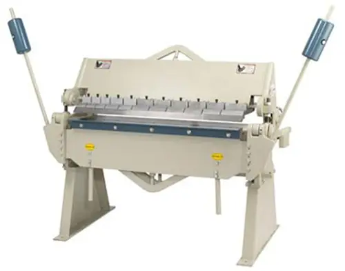
It is the most common type among various press brakes, also known as a sheet metal brake. Manual press brakes require manual adjustments of the bending dimensions and angles during use.
It consists of a worktable, supporters, and a clamping plate. The worktable is mounted on supporters, which consist of a base and pressure plate.
Manual press brakes are more complex to operate than other types of press brakes, so it is necessary to confirm the bending size and angles before starting mass production.
After completing one batch of mass production, adjustments to the bending size and angles must be made for continued production.
(2) Hydraulic press brake
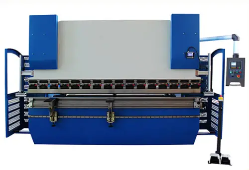
The hydraulic press brake uses the principles of hydraulics to generate a considerable amount of force that can be used to manipulate the material being worked on.
Hydraulic press brakes are more advanced than mechanical ones. They use hydraulic fluid, which is controlled by a hydraulic pump, to exert pressure on the piston, causing it to move and create the bending action. The pressure exerted is proportional to the amount of fluid pumped, which allows for precise control over the bending process.
(3) CNC press brake
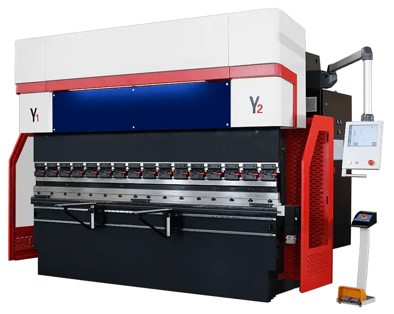
An electro-hydraulic servo press brake is a type of sheet metal processing equipment that offers high precision and efficiency. The following components are included in its design:
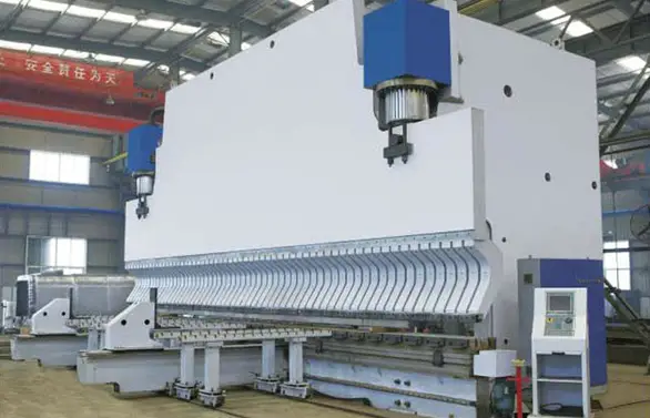
The CNC press brake is a highly efficient and precise sheet metal processing equipment that performs bending by controlling the ram stroke and back gauge.
The operator only needs to input the number of pieces to be bent and the bending angle for each step, and the CNC press brake will perform the bending process according to these specifications.
Advanced CNC press brakes adopt hydro-electric servo systems and grating rulers to form a closed-loop control system, ensuring high control accuracy, bending accuracy, and repositioning accuracy.
With advancements in technology, electro-hydraulic servo synchronization technology is being adopted to upgrade the system, providing numerous advantages.
Classified by synchronization, the hydraulic press brake can be divided into:
Classified by movement, the hydraulic press brake can be divided into:
Further reading:
How does a hydraulic press brake work?
In simple terms, the press brake works by using the relative motion of the punch and die, which are fixed on the upper and lower worktable, to achieve bending of sheet metal materials through hydraulic transmission.
A more detailed explanation:
The hydraulic press brake machine incorporates numerical control technology, servo, and hydraulic technology.
The left and right cylinders are driven to extend and retract by controlling the action of the valve. This movement drives the ram of the press brake machine to rise and fall.
The synchronous action of the ram is achieved through the combination of grating signal feedback and proportional valve flow, which is controlled by the CNC system.
The numerical control system also features a display screen for human-machine interaction and simulation of the bending process.
The CNC system controls the opening of the two valves for the left and right cylinders.
If necessary, the flow in the cylinder can be redirected by the servo valve, causing the upper beam to move linearly in a vertical direction.
The amount of movement is determined by the newly measured pulse count.
The signal from the CNC controller is converted into a hydraulic signal to control the action of the valve through the servo valve.
Each cylinder in the hydraulic system has its own independent control circuit, servo valve, and filling valve.
The bending of the workpiece at different angles can be achieved in one operation.
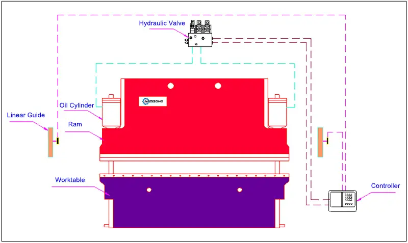
Hydraulic Press Brake Working Principle Diagram
Further reading:
(1) Suitable for small batch and multi-variety production:
The press brake allows for versatility with a single set of punch and die, making it suitable for producing a wide range of materials and parts.
(2) Low cost and long lifespan of bending dies:
Each set of bending die costs only a few thousand yuan, and the manufacturing process is straightforward, eliminating the need for repeated trials.
Moreover, each set of die can last for at least 10 years, reducing the overall cost of die manufacturing.
(3) Capable of producing “S” and “U” shaped parts:
In stamping molding, producing “U” shaped parts is particularly challenging. Press molding requires a certain amount of rebound, which can lead to difficulties in fitting the punch and die together.
The press brake, on the other hand, solves this issue by performing multiple bending operations.
(4) Ideal for trial production of new products:
The versatility of a press brake allows for the production of parts with different shapes, sizes, and angles using a single set of punch and die.
This makes it ideal for trial production of new products without incurring additional costs.
(5) Capable of forming a variety of polyggon shapes with different heights:
The press brake machine can produce multi-bend parts with different edge heights by adjusting the material and angle settings.
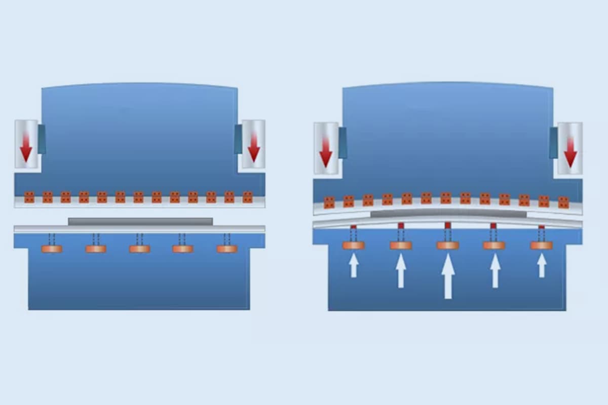
(6) Deflection compensation function:
When bending long workpieces, there can be a significant deviation between the forming angle of the middle and the sides, leading to uneven angles.
The press brake, however, has a deflection compensation function that allows for adjusting the angle at each position, ensuring straight bending and reducing the need for manual adjustment and repair.
This streamlines the production of long parts, reduces labor intensity, and improves product quality.
(1) Requirements for Material Thickness
Materials used in bending must meet certain thickness requirements.
As a rule of thumb, materials with a thickness of no more than 50mm can be easily bent, but those with a thickness greater than 50mm require substantial bending force.
Commonly used press brakes in enterprises have capacities of 400t, 300t, 160t, and 80t.
(2) Risk of Fracture during Bending
During the bending process, edges and corners of the material can develop burrs or oxide layers, which can lead to cracking or fracture of the material during bending.
This makes it challenging to ensure the quality of the final product.
(3) Indentation during Bending
Indentation is a frequent quality issue that occurs during bending. In some cases, the chosen bending die may not be suitable or an appropriate die set must be used, resulting in unavoidable indentation.
In such cases, an additional grinding process is necessary, and the thickness of the polished material and parts must be tested.
Deep indentations can result in scrapping of materials and parts, increasing the cost.
(4) Slippage during Bending
During bending, some materials may slip, causing the bending part to turn out.
Square materials typically do not encounter this issue, but irregular materials may slip easily, resulting in non-compliance with process standards.
Further reading:
Choosing the right material for a press brake job is essential for ensuring a successful outcome. Carefully consider material properties, as different materials have different strengths, ductilities, and load capacities. It’s also important to know the limits of the specific press brake you are using, as this will help avoid machine damage and possible accidents while operating.
Proper Setup and Maintenance
A well-maintained press brake is crucial for achieving desired results. Regularly inspect the machine for wear and tear, ensure all parts are lubricated and functioning correctly, and keep the workspace clean to prevent mishaps. When setting it up, use the correct dies, tooling, and back-gauges for the bend you need. Machine calibration is also essential to maintaining the desired bend accuracy.
Best Practices for Bending
Some techniques can help improve the quality of your press brake work:
The specifications of the press brake machine encompass various aspects including nominal pressure, workbench length, workbench height, ram stroke, maximum opening height, ram stroke adjustment, column spacing, throat depth, ram speed, main motor power, oil pump, maximum system pressure, overall dimensions, among others.
It is important to note that the parameters of press brake machines produced by different manufacturers can vary.
Therefore, when making a purchase, it is crucial to carefully compare these parameters to ensure that the technical specifications of the machine meet your needs and requirements.
Further reading:
Press brakes are widely used in energy, transportation, automobile, machinery, metallurgy, shipbuilding, aviation, military, agricultural machinery, petroleum machinery, power generation industries.

Further reading:
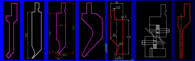
Press brake tooling is an essential component of press brake machines that helps to ensure the accuracy and quality of the final bent parts. It is composed of a punch and a die that are used to shape and bend metal sheets or plates into the desired shape.
The tooling is made of high-strength materials, such as hardened steel, to withstand the high pressure and forces during press brake operations.
There is a wide range of shapes and sizes available to cater to different applications and workpieces. The die used for forming has a cavity, while the die used for separation has a blade edge.
Press brake tooling consists of various components that work together to bend and shape metal sheets. The most important elements in press brake tooling are punches and dies, as they directly perform the bending process.
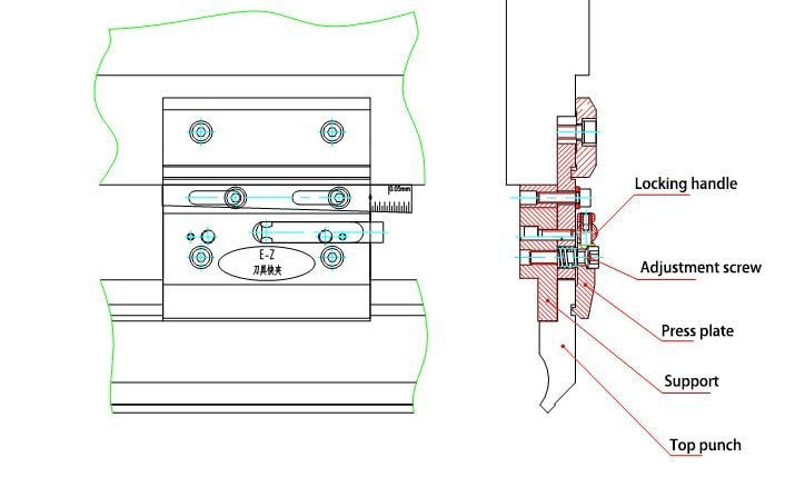
Punches, also known as the upper tool, are attached to the upper part of the press brake. These tools are responsible for applying pressure to the metal sheet, forcing it into the dies. Punches are available in different shapes and sizes, depending on the desired bend and the type of material being processed. Some common punch types include:
Dies, also known as the lower tool, are situated at the bottom part of the press brake. They form a cavity or a groove to accommodate the metal sheet and the punch. When the punch presses the metal sheet into the die, it forms the desired bend. Some common die types are:
Careful selection of punch and die combinations is crucial for achieving the desired results. Factors such as material type, thickness, bend radius, and press brake tonnage should all be considered when choosing the proper tooling. Proper maintenance and handling of the tools are also imperative, as they directly impact the quality of the finished product.
Further reading:
You may be wondering who makes the best press brake.
The following press brake manufacturer ranking list will certainly assist you in choosing the ideal press brake manufacturer. We may include our press brake reviews below the list in the near future.
Before performing maintenance or cleaning on the press brake machine, align the top punch with the bottom die, then turn off the press brake until the work is completed.
If it is necessary to start the machine or carry out other operations, make sure to select the jog mode for safety.
Here is a press brake maintenance checklist:
Hydraulic oil circuit
Filter
Hydraulic parts
As a press brake operator, it is important to read through the following analysis of common press brake failures in order to possibly prevent and resolve significant issues.
Further reading:
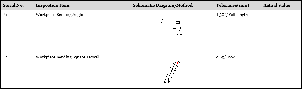
Brief Description
The inspection method and accuracy range shall be based on GBT-14349-2011-Metal Press Brake- Precision
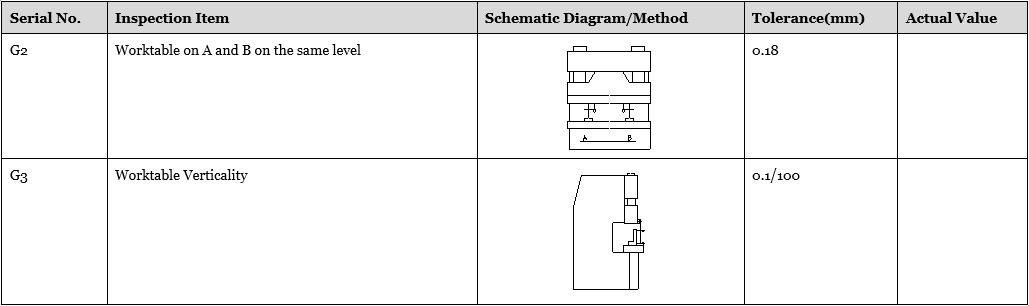
Note: the worktable is floated, inspection G2, G3 shall refer worktable vertical plate as a benchmark.
You may be wondering about the size of press brake you need. How do you calculate the press brake forming force? What’s the formula for calculating press brake tonnage?
The easiest way to determine the required press brake capacity for your bending work is to refer to the chart below.
Press brake bending chart (metric)
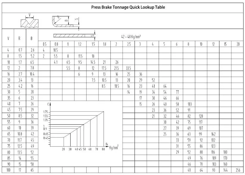
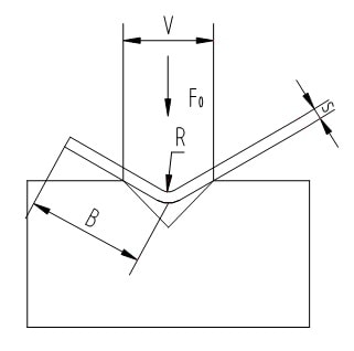
The bending force referred to in the above quick reference chart is based on the following conditions:
The required bending force per meter (T/m) when the lower die opening and plate thickness are confirmed, and the material’s tensile strength is 45kg/mm² (450N/mm²).
When the material has a different tensile strength of σ (kg/mm²), the required bending force per meter (T/m) can be calculated using the following formula.
F1 = F0·σ/450 (T/m);
See also:
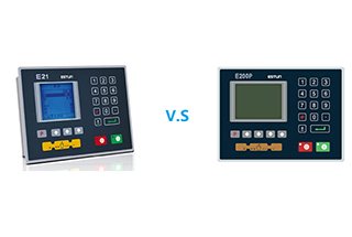
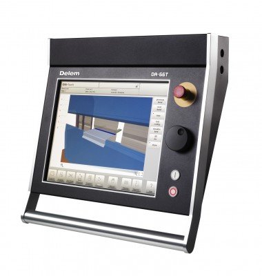
There are two popular press brake controllers, namely the one from China’s Estun, which is the exclusive agent of DELEM control in China, and the other one is DELEM from the Netherlands.
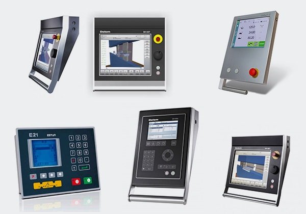
See also:
The key factors for a press brake machine are divided into two parts: the machine itself, such as its quality and accuracy, and the control system.
You can download the installation and operation manual for press brake controllers in PDF form from the following link.
Operation Manual:
Installation Manual:
The above operation manual and installation manual of press brake controllers provide clear explanations of programming and setup. Please download them from the provided link and read them carefully.
Instructions on How to Use a Press Brake:
As an example, here is a simple introduction on how to use a hydraulic press brake to fabricate Q235 mild steel:
First, connect the power, turn on the key switch on the control panel, and then press the pump to start.
You should be able to hear the sound of the oil pump rotating. (The machine will not start running at this time)
Pay attention to stroke adjustment for the press brake operation.
This must be tested before bending. Ensure that there is clearance equal to the thickness of the plate when the top punch is down at the bottom of the lower die, otherwise the mold and press brake may be damaged.
The stroke adjustment can be performed through electric quick adjustment or manual fine adjustment.
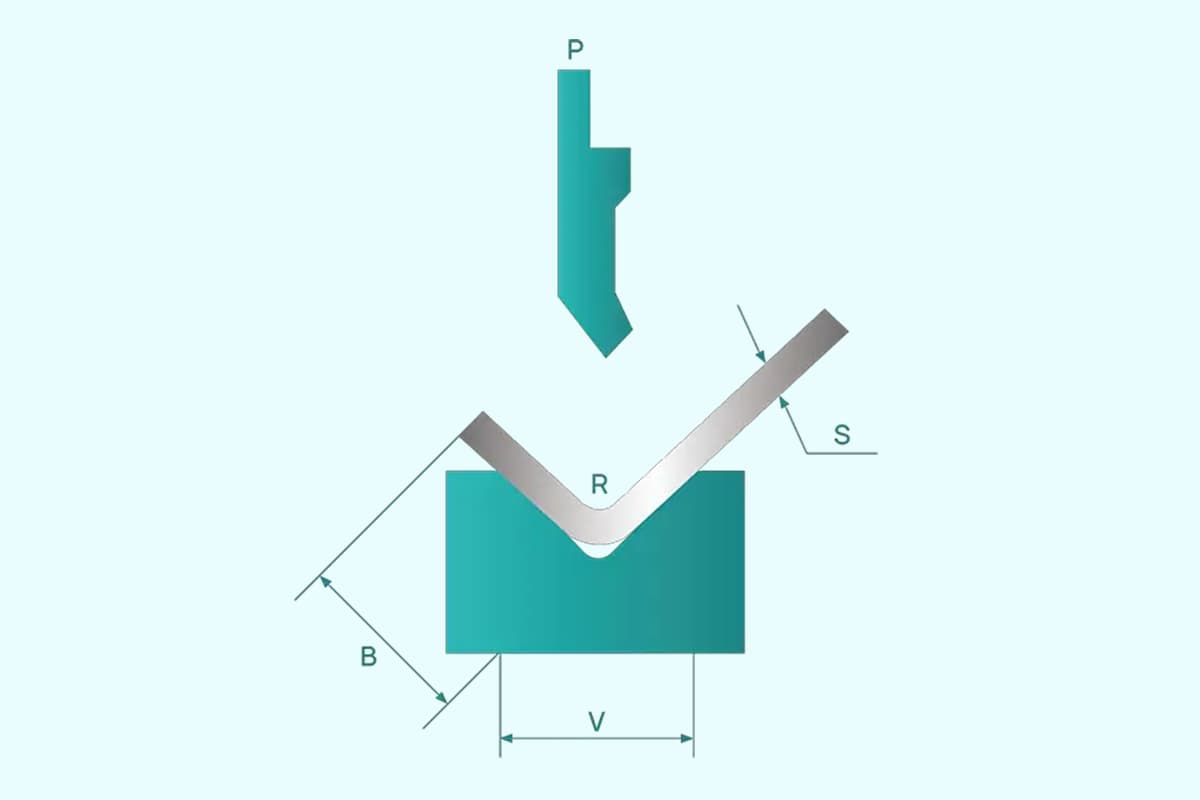
For V-width selection, the width of the V opening should typically be 8 times the thickness of the plate. For example, when bending a 4mm plate, you should choose a 32mm V-opening die.
The back gauge adjustment usually has both electric fast adjustment and manual fine-adjustment.
Step down the pedal switch to start bending. You can stop the machine at any time by releasing the foot.
If you release your foot, the bending machine will stop and you can continue bending by stepping down the switch again.
Here, we provide press brake operation manuals to guide you in operating the press brake.
Furthermore, by reading the articles in our bending category, you can gain knowledge about various aspects of press brake and sheet metal bending.
It is recommended to take your time to carefully read and learn from these articles.
Training of press brake
Training for press brake usage and programming can also be acquired by referring to the manuals.
These manuals can be easily downloaded from the link provided above and can be studied at your convenience, wherever you are and at any time.
Further reading:
Sometimes, workshop owners only need to bend a few pieces of steel, making it not cost-effective to purchase a brand new press brake.
As a result, they may opt to build their own press brake for simple bending purposes, creating a homemade metal brake press.
Here, I have collected some videos on building a home-made press brake. I hope that these tutorials will help you make one on your own.
In the coming years, the press brake industry is expected to see a significant increase in the adoption of automation. This trend is driven by the need to improve productivity, accuracy, and consistency in manufacturing processes. Companies have started integrating robotic systems into their press brake operations, making it possible to handle complex bending tasks with ease and precision.
Automated press brakes not only increase efficiency but also reduce the dependency on skilled labor, as they can operate with minimal human intervention. Moreover, the use of advanced sensors and smart controls ensure better repeatability and quality in the products.
The future of the press brake industry also includes a focus on environmentally friendly technologies that minimize the impact on the environment. Manufacturers are working on the development of sustainable materials and energy-efficient machinery to contribute to a greener industry. Some of the key advancements in this area include:
These trends indicate that the press brake industry is continually evolving and adopting innovative technologies to meet the demands of modern manufacturing. As a result, it is expected that these advancements will lead to a more efficient, sustainable, and competitive industry in the future.
How much does a press brake cost? Or what is the price of a press brake?
The cost of a press brake machine is largely determined by its bending force, length, and control system.
Other factors that influence the price include the brand, type, specifications, and market.
To provide a general idea of the price range for press brake machines, we have created a reference table for both NC and CNC press brakes.
Press Brake Price Table (USD)
| Model | NC Press Brake | CNC Press Brake |
|---|---|---|
| 40T*2200 | 4800 | 19000 |
| 40T*2500 | 4850 | 20000 |
| 50T*2500 | 5200 | 20500 |
| 63T*2500 | 6300 | 21000 |
| 63T*3200 | 7300 | 22000 |
| 80T*2500 | 7900 | 23000 |
| 80T*3200 | 9200 | 24000 |
| 80T*4000 | 10500 | 23500 |
| 100T*2500 | 8800 | 24000 |
| 100T*3200 | 9900 | 25000 |
| 100T*4000 | 11500 | 26000 |
| 125T*2500 | 9500 | 25000 |
| 125T*3200 | 10800 | 26000 |
| 125T*4000 | 12500 | 27500 |
| 160T*2500 | 13000 | 27000 |
| 160T*3200 | 14500 | 29000 |
| 160T*4000 | 16000 | 32000 |
| 160T*5000 | 20500 | 36500 |
| 160T*6000 | 24000 | 43000 |
| 200T*3200 | 16000 | 32000 |
| 200T*4000 | 18500 | 36500 |
| 200T*5000 | 23000 | 45000 |
| 200T*6000 | 27000 | 48000 |
| 250T*3200 | 24000 | 38000 |
| 250T*4000 | 27000 | 43000 |
| 250T*5000 | 32000 | 49000 |
| 250T*6000 | 35000 | 55000 |
If you’re in search of the perfect hydraulic press brake machine for your needs, then you should definitely read this comprehensive guide on selecting the right machine.
This article offers a complete overview of the press brake world, starting with a definition of a press brake, followed by an explanation of the different parts of a hydraulic press brake.
It covers different types of press brakes, including manual, hydraulic, and NC/CNC types, and provides a comparison of the pros and cons of NC press brakes versus CNC press brakes.
This guide also highlights key factors to consider when selecting a press brake and provides useful tips on how to choose the right machine.
In short, it is a must-read for anyone who’s looking to purchase a press brake machine.
Related reading: Press Brake Buying Guide

As the founder of MachineMFG, I have dedicated over a decade of my career to the metalworking industry. My extensive experience has allowed me to become an expert in the fields of sheet metal fabrication, machining, mechanical engineering, and machine tools for metals. I am constantly thinking, reading, and writing about these subjects, constantly striving to stay at the forefront of my field. Let my knowledge and expertise be an asset to your business.