The Impact of Lower Die Opening on Air Bending Dimensions
How does the size of the lower die opening affect the final dimensions of metal parts in air bending? This question is crucial for ensuring precision in metal fabrication. The article explores the impact of different lower die openings on the accuracy and consistency of bent metal parts. By understanding this relationship, readers will learn how to achieve more precise bends and improve the quality of their metalworking projects.
Bending is a metalworking process that involves shaping metal blanks into desired angles and shapes through techniques such as bending and drawing. It offers high flexibility, wide usability, and cost-effectiveness, making it a widely used method in the sheet metal processing industry.
In the production of steel structures for modern electric locomotives, crucial structural parts are mostly made of medium-thick plates with large R-angle designs. These workpieces are typically bent using CNC press brakes, which use the simple up-and-down motion of a ram and a bending tool to form complex shapes.
However, it has been observed that under the same processing equipment, materials, and upper dies, workpieces formed through air bending can vary in size from batch to batch. After eliminating the effects of differences in material thickness and internal stress relief due to different furnace numbers, it was determined that the cause of the size variation was the use of different lower die opening sizes by the machine operator during the bending operations.
This article aims to provide production guidance by briefly discussing the impact of lower die opening size selection on the forming dimensions in plate bending.
Two common bending methods and comparison
Air bending
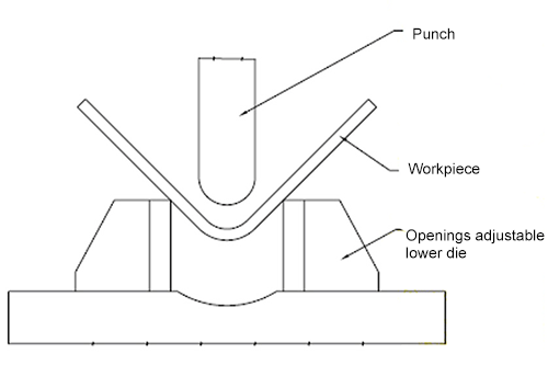
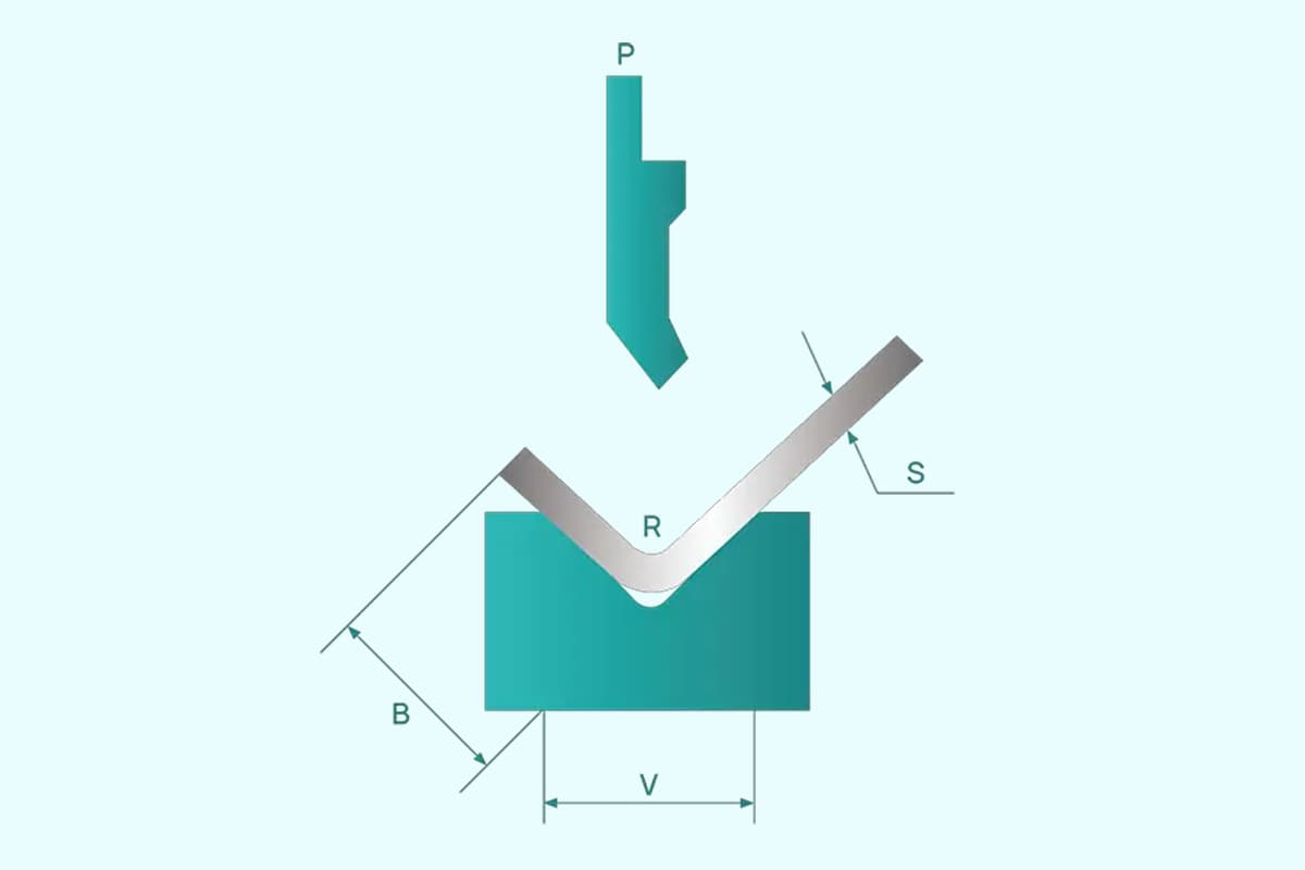
Air bending, also known as gap bending, is a metalworking process in which the upper and lower dies are not pressed together. The desired bending angle is achieved by adjusting the depth of the upper die into the lower die. The deeper the upper die enters the lower die, the smaller the bending angle will be, and vice versa.
To account for the bending rebound, the bending process must be over-bent to ensure that the final bending angle, after the rebound, matches the design angle. The bending state can be visualized in Figure 1.
Figure 1 Air bending diagram (simplified lower die radius)
Today, widely used CNC bending machines can automatically calculate the depth of bending through their CNC systems. The machine is equipped with a feedback correction system and a hydraulic unit that allow for automatic control of the bending angle, minimizing operator involvement.
However, despite these advancements, it is still challenging to achieve the programmed angle in a single bending operation due to various factors, such as deviations in the calculation model, errors in sheet thickness, differences in material types, and stress release within the material. As a result, trial bending is still necessary before mass production.
The process method discussed in this article is air bending.
Coining
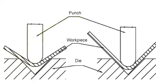
With coining, the sheet is placed between the upper and lower dies and bent freely at the start. As the upper die is pushed down, the material and the surface of the lower die gradually come closer together, and the bending area of the material decreases until the lowest point of the stroke, at which point the material is fully pressed against the upper die. The desired bending angle and radius are achieved through the application of bending force, as illustrated in Figure 2.
Fig. 2 Coining process (simplified lower die radius)
Air bending vs coining
Due to its high flexibility, wide range of applications, low cost, and other advantageous characteristics, air bending has surpassed coining as the preferred process method for sheet metal processing companies. In comparison to coining, the bending pressure of air bending is typically only one-third, reducing the tonnage requirement for the bending machine and effectively controlling costs.
On the other hand, the angle of the lower die in coining determines the final bending angle of the product, making it less suitable for the current sheet metal market which prioritizes individual customization and flexible production. It is better suited for medium to large-scale production. Additionally, the excessive bending pressure of coining limits its use to processing thin sheets.
Although air bending has some limitations in terms of product accuracy, advancements in bending equipment have gradually reduced this deviation to an acceptable level for most products.
Influence of air bending die opening size on forming dimensions
A simple verification experiment is designed to compare the impact of selecting the die opening size on the size of the bending shape.
Experimental conditions
To ensure the reliability of the verification experiment, measures are taken to minimize the influence of potential external variables on the experimental results. The actual conditions of the experimental site and facilities, the type of materials used in the experiment, the direction of discharge, and the type of dies are taken into comprehensive consideration to minimize their impact on the results. The conditions are detailed in Table 1.
Table 1 Basic conditions of verification experiment
Test-fold and fix to ensure identical positioning dimensions.
10
Detection tools
500mm vernier caliper, wide seating square
50 graduation
Experimental process
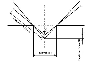
The objective of the verification experiment is to measure the dimensions L1 and L2 of the workpiece after bending and to use the sum L (L=L1+L2) as the comparative value for the experiment. The experimental variable is the size of the lower die opening.
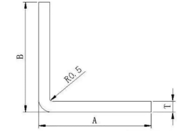
The adjustable opening size of the lower die is utilized to eliminate the influence of other die structural factors on the experimental results. The structure of the specimen is depicted in Figure 3.
Figure 3 Specimen structure
During the experiment, the specimen was first measured using a 500mm vernier caliper after machining, and the linear dimension of the two processing surfaces at its end was recorded as 557.50mm.
Next, the size of the lower die opening was gradually increased and multiple trial bendings were performed. From the test pieces produced under each opening size, the one with the best bending angle was selected using a wide seat square.
The selected specimen’s L1 and L2 values were then measured, and the comparative value L was calculated.
Experimental results
Six different die opening sizes, ranging from 160mm to 400mm, were used in the experiment. From the folded samples, the six best specimens were selected and the dimensions L1 and L2 were measured to obtain the calculated value L (L=L1+L2).
The size L of the workpiece folded using the 160mm lower die opening size was used as the reference size. The deviation was compared to the L values of the other test pieces, and the results are presented in Table 2.
Table 2 The effect of the opening size of the lower die on the bending forming size
NO.
The opening size of the lower die
Calculated value L (L=L1+L2)
Deviation value
1
160
596.12
0
2
180
596.14
0.02
3
200
596.22
0.1
4
300
598.86
2.74
5
350
602.48
6.36
6
400
606.14
10.02
The experimental results indicate a positive correlation between the size of the bending shape and the opening size of the lower die. The theoretical L-value of the specimen after bending was calculated to be 596mm. Using the measured value of 596.12mm for the workpiece folded with a 160mm lower die opening size as a benchmark, it was found that when the opening size is 10 to 12.5 times the sheet thickness, the size falls within the acceptable tolerance for sheet metal parts.
Deviations from the normal workpiece tolerances were observed for lower die openings up to 300mm. The deviation increased to 10.02mm when a 400mm lower die opening size was chosen, a significant deviation from the workpiece size.
These results demonstrate the significant impact that the selection of the lower die opening size has on the size of the formed workpiece in air bending. To ensure the desired dimensions, it is recommended to choose a lower die opening size that is approximately 10 times the thickness of the sheet. However, it is important to consider the R-angle of the bend as well, as using a lower die with an opening that is too small can prevent the ram from moving down far enough, leading to an incomplete bend or even damage to the tooling.
Analysis of the causes of the influence of the opening size of the air bending bottom die on the forming dimension of the medium-thick plate
The experimental results show a positive correlation between the size of the formed bend and the size of the lower die opening. In this experiment, the L-shaped specimen was 557.50mm in length and all specimens were of the same size.
It can be concluded that changes in the size of the lower die opening result in a tendency for the dimensions L1 and L2 to increase when the workpiece is air bent. This change is likely due to a change in the inner R-angle after forming.
As there is no accurate means to measure the inner R-angle after forming, it can be inferred that the size of the inner R-angle is also positively correlated with the size of the lower die opening.
To ensure the accuracy of the formed dimensions of the workpiece, it is recommended to choose the smallest possible opening size for the lower die during bending.
Conclusion
This article focuses on the impact of the size of the die opening on the size of the formed workpiece during air bending of thick plates. A simple verification experiment revealed that, under the same process conditions for air bending, there is a positive correlation between the size of the lower die opening and the size of the formed bend.
In cases where the size of the workpiece is critical, especially if strict requirements are placed on the inner R-angle forming size, it is recommended to use the coining method and corresponding tooling, which can produce twice the desired outcome with half the effort.
It should be noted that the verification experiments described in this article are not highly rigorous or accurate due to limitations in equipment, personnel, measuring tools, and other factors. However, the experimental results can still provide helpful explanations and guidance for production and have practical significance.
As the founder of MachineMFG, I have dedicated over a decade of my career to the metalworking industry. My extensive experience has allowed me to become an expert in the fields of sheet metal fabrication, machining, mechanical engineering, and machine tools for metals. I am constantly thinking, reading, and writing about these subjects, constantly striving to stay at the forefront of my field. Let my knowledge and expertise be an asset to your business.
Ever wondered how press brake crowning devices affect bending precision? This article explores two main compensation methods: lower die convex compensation and upper die convex compensation. It examines their impact…
How does the precision of a press brake impact the quality of metal bending? This article explores the critical link between the manufacturing accuracy of press brakes and the resulting…
Have you ever struggled with sheet metal bending problems that left you scratching your head? In this insightful blog post, an experienced mechanical engineer shares their expertise on tackling common…
Choosing between an electric and hydraulic press brake can significantly impact your business efficiency and costs. Electric press brakes offer superior energy savings, environmental benefits, and faster operation speeds, while…
Have you ever struggled with accurately unfolding sheet metal parts? This article explores the art and science behind sheet metal unfolding calculations. Discover the key concepts, formulas, and techniques used…
Attention all metalworking enthusiasts! Are you tired of guessing the proper tonnage for your press brake? Look no further! In this blog post, we'll dive into the world of press…
Attention all sheet metal fabricators and designers! Are you struggling to determine the optimal bending radius for your projects? Look no further! In this blog post, we'll dive into the…
Ever wondered why your metal bends aren't always perfect? The secret lies in press brake crowning, a technique that ensures precision and quality in metal fabrication. This article will reveal…
Have you ever wondered what makes press brake dies so fascinating? In this captivating blog post, we'll delve into the intricate world of these essential tools that shape the metal…