Weld deviation/deflection
1. Laser
Possible causes:
1) Unreasonable weld offset setting
Connect with basis HMI Software, check the current offset, and determine how to change it according to the direction of welding deviation.
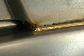
2) The protective lens needs to be replaced
There are dense stains and burns in the center of the lens, which need to be replaced
3) Whether the position of light and wire is aligned
Observe the relative position of the light wire through the display, and the end of the welding wire shall be at the center of the cross fork.
4) Is the cable harness connecting the force sensor and the top controller on the welding joint free?
Empty the track and observe whether the cable is pressed or involved by other cables during walking.
Raw materials and parts
1) The y-direction position deviation of the weld formed between the top cover and the side wall exceeds the tolerance.
Temporary scheme adjustable track
2) The gap between the top cover and the side wall is out of tolerance.
The temporary scheme can appropriately increase the wire feeding speed.
Welding wire
The wire feeding speed is too slow, the wire feeding is not smooth or the speed setting is too low.
1) Observe whether the small motor current on the wire feeder is too large, which indicates that the wire feeding resistance is large.
2) Observe the actual wire feeding speed displayed on the process cabinet to see if it is out of tolerance.
Take out the wire three times at a fixed time and speed, measure the length, and check whether the deviation from the theoretical value is too large.
If it exceeds 3%, it means that the wire feeding is hindered, which will affect normal welding.
3) If the condition is not good, check whether the 690mm wire feed pipe at the front end of the wire feeder needs to be replaced;
Whether the pressing force of the guide roller needs to be recalibrated;
If the wire feeding nozzle is burnt and deformed, it needs to be replaced.
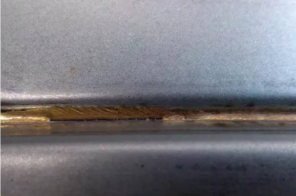
Uneven weld surface
1) The wire guide nozzle is worn, resulting in wire jitter.
Check the wire guide nozzle. If it is deformed and burned, replace it with a new one.
2) There are dense stains in the center of the laser head protective lens, resulting in the fluctuation of light transmittance
Check the protective lens. If there are dense stains or burns in the center of the lens, replace it with a new lens.
3) Insufficient laser power
Check the laser power. If necessary, increase the laser power appropriately.
4) The laser welding surface of the side wall is uneven.
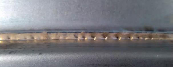
Stomata
1. Workpiece cleanliness:
Excess zinc and foreign substances.
Check the conformity of incoming parts (cleaning, foreign substances).
2. Air flow influence
Check the compressed air on the laser head and the compressed air on the fixture (air leakage).
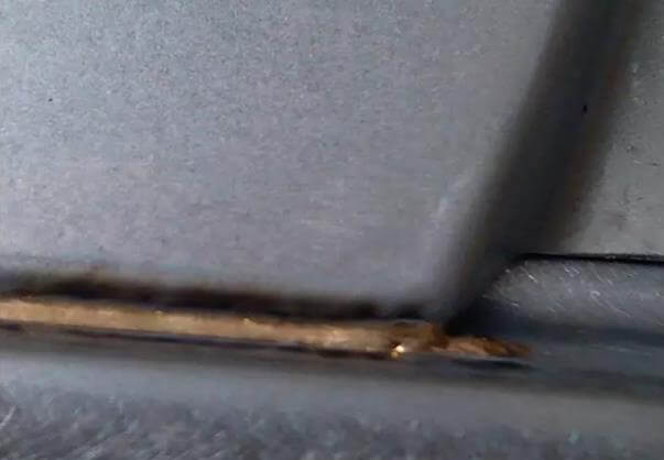
Collapse
1. Excessive laser power
Reduce the laser power appropriately
2. Wire feeding speed is too low.
Check the set value and actual value of wire feeding speed. If necessary, correct or calibrate the wire feed speed.
3. Uneven robot speed
Check whether the parameters of the robot are reasonable, especially where there are CNT and ACC, and where the robot attitude changes greatly.
4. The gap between the top cover and the side wall is abnormal.
Check whether the part clearance meets the requirements of smooth transition within 0.3mm.
Starting and ending arc welding tumor
1. Whether the position of arc starting and ending points is appropriate.
Check the position of arc starting and ending points in the empty track, and make corresponding adjustment in case of deviation.
2. Whether the laser delay and wire feeding delay are reasonably matched.
1) The arc starting overlap can delay the wire feeding
2) The arc stopping overlap can delay the light off
3. The arc starting and ending position of parts fluctuates in the X direction.
Starting and ending arc burn through
1. Whether the position of arc starting and ending points is appropriate.
Check the position of arc starting and ending points in the empty track, and make the corresponding adjustments in case of deviation.
2. Whether the laser delay and wire feeding delay are reasonably matched.
1) Arcing burn-through can delay the light output or reduce the laser power at arcing.
2) Arc stopping and burn-through can delay the stop of wire feeding.
3) X-direction fluctuation of arc starting and ending position of parts.
Welding interruption
1) Process cabinet alarms “laser source error” and “laser program number loss”.
Check the laser to confirm the parameters, or contact the laser manufacturer.
2) Process cabinet alarms “no sheath wire” or “welding wire blockage”.
1) Observe the actual wire feeding speed to see if it exceeds 10%. If yes, check the wire feeding pipeline.
2) Wire feeding speed sensor failure