Have you ever wondered how welding transforms separate metal pieces into a unified whole? This article explores the fascinating world of weld joints, examining their types, mechanical characteristics, and the critical factors in their design. Discover how these joints impact the strength and durability of metal structures.
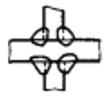
Arc welding joints consist of four parts: the weld seam, the fusion zone, the heat-affected zone, and the base material near the weld seam.
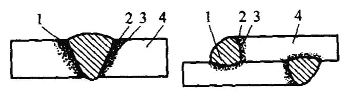
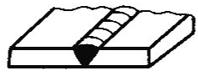
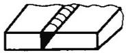
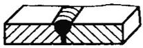
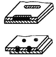
Composition of the Fusion Welding Joint a) Butt Joint b) Lap Joint
1 – Weld Metal 2 – Melted Wire 3 – Heat-Affected Zone 4 – Base Material
1. Mechanical Characteristics of Welded Joints
Welding process imbues the joint with the following mechanical characteristics:
1) Heterogeneous Mechanical Performance of Welding Joints
Owing to various metallurgical processes taking place during welding, and due to the different thermal cycles and strain cycles affecting different areas, significant disparities in the structure and properties of these areas occur. This results in heterogeneous mechanical performance of the entire joint.
2) Uneven Stress Distribution and Concentration in Welding Joints
Geometric discontinuities inherent in welding joints lead to an uneven distribution of working stress and subsequent stress concentration. When welding defects are present, or when the shape of the welding seam or joint is impractical, the concentration of stress intensifies, affecting the joint strength, particularly its fatigue strength.
3) Residual Stress and Deformation Due to Uneven Heating During Welding
Welding is a localized heating process. During arc welding, the temperature at the weld seam can reach the material’s boiling point, but it rapidly decreases away from the seam down to room temperature. This uneven temperature field leads to residual stress and deformation within the weldment.
4) High Rigidity of Welding Joints
Through welding, the seam and the components become unified, yielding a higher degree of rigidity compared to riveted or shrunk joints.
2. Basic Forms of Joints
Welded Joint (also referred to as a Joint): A joint connected by welding.
Commonly used welded joints:
Butt Joint, T-joint, Cross Joint, Lap Joint, Corner Joint, Edge Joint, Sleeve Joint, Bevel Butt Joint, Flanged Joint, and Double-V Butt Joint, among others.
The basic types of welded joints.
Name
Weld seam formation
Name
Weld seam formation
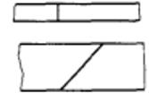
Butt Joint
Terminal Connector
T-Joint
Oblique Butt Connector
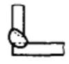
Corner Joint
Flanged Connector
Lap Joint
Sealed Butt Connector
1. Butt Joint
A butt joint is formed by welding together the edges of two workpieces lying in the same plane. This type of joint is the most commonly adopted and the most refined in various welded structures, boasting superior stress handling, high strength, and efficient use of metal materials.
However, since it’s an edge-to-edge connection, the processing and assembly requirements for the connected pieces are quite high.
In welding production, the weld seam of the butt joint is typically slightly higher than the base material’s surface. The presence of this excess height results in a non-smooth surface on the component, causing stress concentration at the transition between the weld seam and the base material.
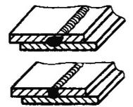
2. T-Joint
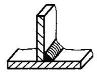
A T-joint (or cross joint) is formed by connecting perpendicular pieces using a fillet weld. T-joints can withstand forces and torques from various directions. This form is most commonly found in box structures and is also prevalent in pressure vessel manufacturing, including tube-to-shell connections and the joining of manhole reinforcement rings to the vessel body.
Because of the sharp transition from the weld seam to the base material in T-joints, there’s significant distortion of the force line under external forces, leading to a very uneven and complex stress distribution. This results in substantial stress concentration at both the root and toe of the fillet weld. Ensuring full penetration is one crucial measure to reduce stress concentration in T-joints.
T-Joint
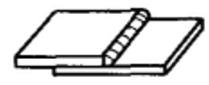
3. Lap Joint
A lap joint is created by overlapping two plates and then conducting a fillet weld on the end or side, or by adding a plug or groove weld. Due to the misalignment of the two plate centerlines in the lap joint, an additional bending moment is generated under load, which can affect weld strength.
Hence, lap joints are typically not utilized for the main pressure-bearing elements in boilers and pressure vessels.
The significant shape alteration in the components due to lap joints leads to a more complex stress concentration compared to butt joints, resulting in an extremely uneven stress distribution across the joint.
Within lap joints, based on the different directions of stress acting on the overlap fillet weld, these welds can be categorized as frontal, lateral, or diagonal fillet welds.
Lap Joint
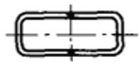
In addition to welding two steel plates stacked on the end or side, lap joints also involve groove welding and plug welding (round holes and elongated holes). The structure of a groove-welded lap joint is shown in the figure.
First, the workpiece to be connected is punched into a groove, and then the groove is filled with weld metal. The cross-section of the groove weld is rectangular, and its width is twice the thickness of the connected component. The length of the groove should be slightly shorter than the lap length.
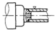
Plug welding involves drilling holes in the plates to be joined, replacing the groove in groove welding, and using weld metal to fill these holes, thereby connecting the two plates. Plug welding can be divided into two types: circular hole plug welding and elongated hole plug welding, as shown in the figure.
4. Corner Joint
A corner joint is formed when two plates are welded at their edges at a certain angle. Corner joints are commonly used in box structures, saddle pipe joints, and connections with cylindrical bodies. The connection between fire tubes and end caps in small boilers also takes this form.
Similar to T-joints, single-sided corner joints have extremely low resistance to reverse bending moments. Unless the plates are very thin or the structure is not critical, bevels should generally be made for double-sided welding, otherwise, quality cannot be ensured.
When selecting the type of joint, consider primarily the structure of the product, as well as factors such as stress conditions and processing costs.
For instance:
Butt joints are widely used because they distribute stress evenly and save on metal. However, butt joints require precise cutting dimensions and assembly.
T-joints mostly endure minor shear stress or serve merely as connecting welds.
Lap joints do not demand high assembly precision and are easy to assemble, but their load-bearing capacity is low, so they are generally used in non-critical structures.
The requirements for weld quality, weld size, weld position, workpiece thickness, geometric dimensions, and working conditions in the design of welded joints determine the diversity in selecting welding methods and formulating processes. Reasonable design and selection of welded joints not only ensure the strength of the welds and the overall steel structure but also simplify the production process and reduce manufacturing costs.
Main factors in designing and selecting welded joints:
1. Ensure the welded joint meets usage requirements.
2. The joint form can accommodate the chosen welding method.
3. The joint form should be as simple as possible, with flat welding and automatic welding methods used whenever possible. Avoid overhead and vertical welding and do not place the maximum stress on the weld.
4. The welding process should ensure the welded joint can function properly at the design temperature and in corrosive media.
5. Welding deformation and stress should be minimized to meet the technical, personnel, and equipment conditions required for construction.
6. Design the weld to serve as a connecting weld whenever possible.
7. The welded joint should be easy to inspect.
8. The preparation for welding and the cost of welding should be low.
9. Avoid choosing and designing oversized weld angles for fillet welds. Tests show that large fillet welds have a lower load-bearing capacity per unit area.
The designed weld seam position should facilitate welding and inspection
To reduce stress concentration at the lap weld seam, it should be designed as a joint with certain stress relief
Cut off the sharp corners of the reinforcement ribs
Weld seams should be distributed
Avoid cross weld seams
Weld seams should be designed on or near the neutral axis in a symmetrical position
The weld seams subject to bending should be designed on the tension side, not on the unwelded compression side.
Avoid placing weld seams where stress is concentrated.
Weld seams should steer clear of areas with maximum stress.
The processing surface should be free of welding seams.
The position of the automatic welding seams should be designed where the adjustment of welding equipment and the number of workpiece flips are minimized.
3. Basic Forms of Weld Seams
A weld seam is the joint formed after welding parts together.
Categories:
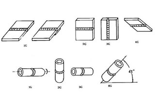
1. Based on spatial positioning, it can be divided into: flat weld seams, horizontal weld seams, vertical weld seams, and overhead weld seams.
2. Based on the method of jointing, it can be categorized into: butt weld seams, corner weld seams, and plug weld seams.
3. Based on continuity, it can be classified as: continuous weld seams and intermittent weld seams.
4. Based on load-bearing, it can be split into: working weld seams and contact weld seams.
The weld seam is a crucial component of the welded joint. The basic forms of the weld seam are the butt joint weld seam and the corner joint weld seam.
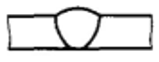
1. Butt Weld Seams:
Butt weld seams are formed along the junction between two parts. They can either have an un-grooved (or I-shaped groove) or a grooved configuration. The surface shape of the weld seam can either be convex or flush with the surface.
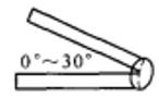
2. Corner Weld Seams:
Cross-Sectional Shape of Corner Weld Seams
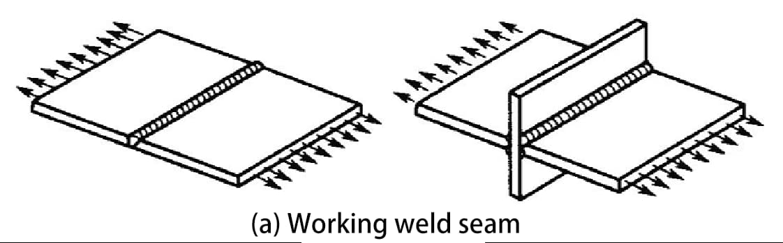
4. Working Weld Seams and Contact Weld Seams
Working Weld Seams (also known as Load-Bearing Weld Seams)
These are weld seams that, in series with the welded parts, primarily bear loads. Should these seams rupture, the steel structure would immediately suffer severe damage.
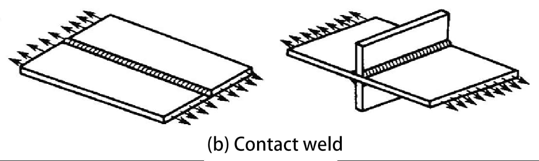
Contact Weld Seams (also known as Non-Load-Bearing Weld Seams)
These are weld seams that parallelly unify two or more welded parts (i.e., providing connectivity). These seams do not directly bear loads and are subject to minimal force during operation. If such a seam were to rupture, the structure would not fail immediately.
A groove is a trench formed by machining certain geometric shapes at the to-be-welded parts of a workpiece according to design or process requirements.
Groove preparation:
The process of machining the groove using mechanical methods, flame, or electric arc.
Purpose of groove preparation:
(1) To ensure the arc penetrates deep into the root of the weld seam for complete fusion, to achieve an optimal weld seam formation, and to facilitate slag removal.
(2) For alloy steels, the groove also adjusts the ratio of base metal to filler metal (i.e., fusion ratio).
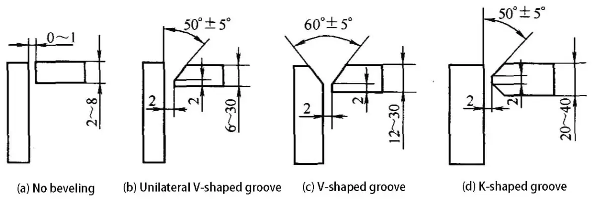
Depending on the thickness of the plate, the welding edges of butt weld seams can be rolled, squared, or machined into V-shape, X-shape, K-shape, and U-shape grooves.
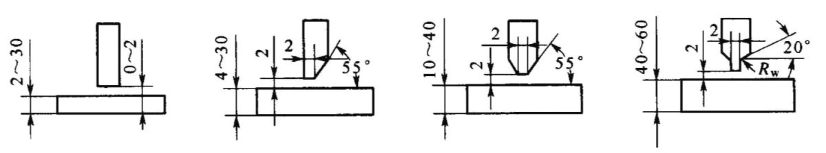
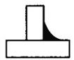
(2) Depending on the thickness of the workpiece, the structure, and load-bearing conditions, the groove shapes for corner joints and T-joints can be divided into I-shape, single-sided V-shape with a blunt edge, and K-shape.
Grooves for Corner and T-shaped Joints
a) I-shape b) Single-Sided V-shape (with blunt edge) c) K-shape (with blunt edge)
2. Principles for Groove Design
The form and dimensions of the groove are primarily chosen and designed based on the thickness of the steel structure, the selected welding method, the welding position, and the welding process. The design should:
1) Minimize the amount of filler material in the weld seam;
In general, for welding workpieces up to 6mm thick using electrode arc welding, or for automatic welding of workpieces up to 14mm thick, it is possible to obtain a qualified weld seam without groove preparation.
However, a gap must be maintained between the plates to ensure the filler metal fills the weld pool, ensuring complete fusion. If the steel plate exceeds the above-mentioned thickness, the arc cannot penetrate through the plate, and groove preparation should be considered.
II. Representation Methods for Welded Joints
To ensure that their designs are accurately and correctly manufactured by fabricators, designers must comprehensively express the technical conditions of the structures and products on design drawings and design specification documents.
For welded joints, designers usually use standardized symbols for weld seams and codes for welding methods. They can also use technical drafting methods, but graphically or textually detailing the welding process requirements and considerations for welded joints can be quite cumbersome and complicated.
Therefore, using standardized symbols and codes to clearly indicate the type, shape, size, position, surface condition, welding method, and related conditions of the welded joint is extremely necessary.
1. Weld Seam Symbols and Welding Method Codes
Weld seam symbols: Symbols marked on the drawings to represent the form, size, and method of the weld seam.
They are regulated by GB/T324-1998 “Symbolic Representation of Weld Seams” (applicable to metal fusion welding and resistance welding) and GB/T5185-1999 “Representation Codes for Metal Welding and Brazing Methods on Drawings.
A weld seam symbol consists of:
basic symbols
supplementary symbols
additional symbols
size symbols of the weld seam
leader lines.
Basic symbols: These symbols represent the cross-sectional shape of the weld seam, approximating the shape of the weld seam’s cross-section.
Weld Seam Names
Cross-sectional shape of the weld seam.
Symbol
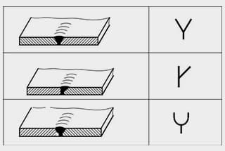
I-shaped Weld Seam
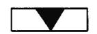
V-shaped Weld Seam
Blunt-edged V-shaped Weld Seam
Single-sided V-shaped Weld Seam
Blunt-edged Single-sided V-shaped Weld Seam
Blunt-edged U-shaped Weld Seam
Sealing Weld Seam
Fillet Weld
Plug Weld or Groove Weld
Flare-V Weld
Spot Weld
Seam Weld
Supplementary Symbols: These symbols represent additional requirements for the surface shape characteristics of the weld seam. Supplementary symbols are generally used in conjunction with basic weld seam symbols when there are special requirements for the surface shape of the weld seam.
Weld reinforcement symbols: These are symbols used to further illustrate certain characteristics of a weld seam.
Name
Form
Symbol
Indication
Symbol with Pad
Indicates the presence of a backing strip at the bottom of the weld seam.
Three-Sided Weld Symbol
Suggests three-side weld seams and the direction of the opening.
Perimeter Weld Symbol
Symbolizes a weld seam surrounding the workpiece.
Field Symbol
Denotes welding performed on-site or at a construction site.
Tail Symbol
Reference to the tail end of the lead line symbol can be made to GB5185-1999 for welding methods and similar notations.”
Weld seam dimension symbols: These are symbols used to represent the dimensions of groove and weld seam features.
Symbol
Name
Schematic Diagram
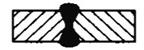
σ
Sheet thickness
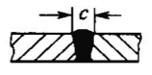
c
Weld seam width
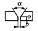
b
Root gap
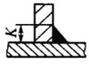
K
Weld toe height
p
Blunt edge height
d
Weld spot diameter
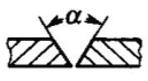
a
Groove angle
h
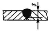
Weld Reinforcement
s
Effective Weld ThicknessSame Weld Joint
N
Quantity Symbol
e
Weld Spacing
l
Weld Length
R
Root Radius
H
Groove height
Leader Line: Composed of an arrowed leader line, two reference lines (horizontal lines) – one solid line and another dashed line, and a tail section.
In order to simplify the annotation and textual explanation of welding methods, the codes representing various welding methods such as metal welding and brazing, as denoted by Arabic numerals according to the national standard GB/T 5185-1999, can be utilized.
The welding method annotations are located at the end of the guide line.
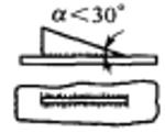
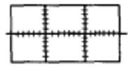
According to the national standard GB/Tl2212-1990 “Technical Drawing – Dimensions, Proportions, and Simplified Representation of Welding Symbols“, when it is necessary to depict welds in a simplified manner on drawings, they can be represented using views, sectional views, or cross-sectional views, or even axonometric views for illustrative purposes.
Generally, only one type of representation is permitted per drawing.
(a) Drawing method of weld end face view (b) Drawing method of weld seam section view (c) Drawing method of weld profile
3. Annotation of Weld Symbols
The National Standard GB/T324-1988, GB/T5185-1999, and GB/T12212-1990 each stipulate the annotation methods for weld symbols and welding method codes.
(1) Weld symbols and welding method codes can be accurately and unambiguously represented through guide lines and relevant regulations.
(2) When annotating welds, first annotate the basic weld symbols on top or below the reference lines, and other symbols are annotated in their respective positions as prescribed.
(3) There are generally no specific requirements for the position of the arrow line relative to the weld, but when annotating V-shaped, single-side V-shaped, J-shaped, etc., welds, the arrow should point to the workpiece with the groove.
(4) When necessary, the arrow line can be bent once.
(5) The imaginary reference line can be drawn above or below the real reference line.
(6) The reference line should generally be parallel to the bottom edge of the drawing, but under special conditions, it can also be perpendicular to the bottom edge.
(7) If the weld and the arrow line are on the same side of the joint, the basic weld symbol is annotated on the side of the actual reference line; conversely, if the weld and the arrow line are not on the same side of the joint, the basic weld symbol is annotated on the side of the imaginary reference line.
When necessary, the basic weld symbol can be accompanied by size symbols and data.
Annotation Principles:
1) The dimensions on the cross-section of the weld seam are marked on the left side of the basic symbol, such as: blunt edge height p, groove height H, weld angle size K, weld seam residual height h, effective thickness of the weld seam S, root radius R, weld seam width C, and weld nugget diameter d.
2) The dimensions in the direction of the weld seam length are marked on the right side of the basic symbol, such as: weld seam length L, weld seam gap e, and number of identical weld seams n.
3) The groove angle α, groove face angle β, root gap b, and other dimensions are marked on the upper or lower side of the basic symbol.
4) The symbol for the number of identical weld seams is marked at the tail end.
5) When there are many dimensions to be marked and they are not easy to distinguish, the corresponding dimension symbol can be added in front of the data.
Name
Schematic Diagram
Labeling
Butt Weld Seam
Intermittent Fillet Weld Seam
Staggered Intermittent Fillet Weld Seam
Spot Weld Seam
Seam Weld Seam
Plug Weld Seam or Groove Weld Seam
4. Simplified Annotation of Welding Joints
In GB/T12212-1990, simplified annotation methods for welding joints are also stipulated under certain circumstances.
As the founder of MachineMFG, I have dedicated over a decade of my career to the metalworking industry. My extensive experience has allowed me to become an expert in the fields of sheet metal fabrication, machining, mechanical engineering, and machine tools for metals. I am constantly thinking, reading, and writing about these subjects, constantly striving to stay at the forefront of my field. Let my knowledge and expertise be an asset to your business.
Welding symbols may seem like a foreign language, but mastering them is crucial for effective communication in the world of mechanical engineering. In this blog post, a seasoned mechanical engineer…
Ever wondered how skyscrapers stand tall or cars stay welded together? This blog uncovers the magic behind electric welding machines. Learn about top manufacturers like Lincoln Electric and Miller Welds,…
Have you ever wondered how the sleek cars, sturdy bridges, and advanced airplanes of today are built? This article explores six cutting-edge welding technologies that are revolutionizing manufacturing, from laser…
Have you ever wondered why some welded structures fail unexpectedly? This article explores the hidden forces at play—welding stress and deformation. Learn how these stresses impact strength, stability, and accuracy,…
Have you ever wondered how to calculate the consumption of welding rods accurately? In this blog post, we'll explore the methods and formulas used by industry experts to estimate welding…
Have you ever wondered about the art of welding and the different positions involved? In this fascinating blog post, we'll delve into the intricacies of welding positions, from flat to…
Ever wondered what "X-weld" or "tack-weld" means? Our latest article breaks down 292 crucial welding terms, offering clear definitions and practical examples. Whether you're a seasoned welder or just starting,…
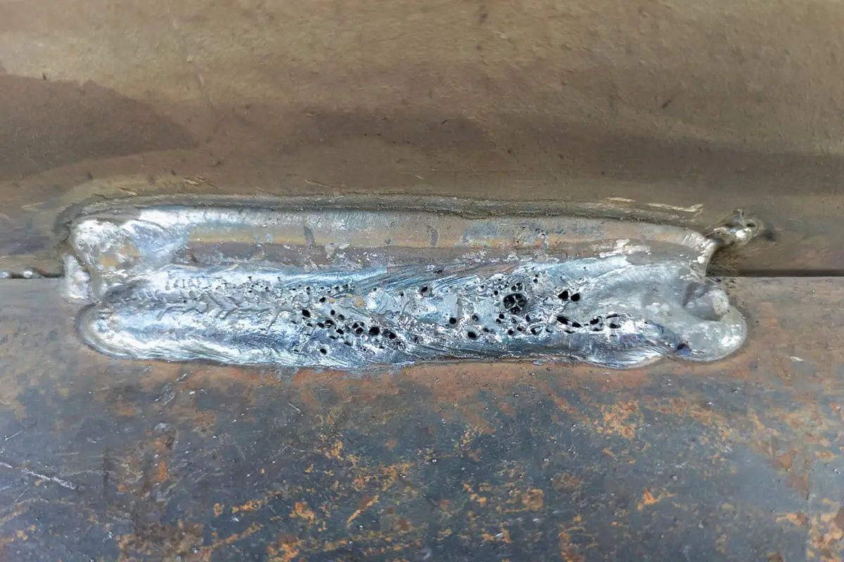
Why does argon arc welding sometimes produce pores, and how can we fix it? Welding porosity, often caused by impurities, improper gas flow, or incorrect technique, can weaken welds and…
Imagine a machine that welds with precision, never tires, and enhances safety in industrial settings. This article explores the fascinating world of arc welding robots, detailing their components, operational procedures,…