What makes martensite so vital in strengthening steel, and how do its different forms impact its properties? This article explores the diverse morphologies of martensite, including lath, flake, butterfly, and ε’ martensite, and their unique characteristics. By understanding these variations, you’ll gain insight into how each type influences the mechanical properties of steel, essential for applications requiring specific strength and toughness.
The martensite structure obtained by quenching plays a critical role in imparting strength and toughness to steel.
However, due to variations in the type, composition, and heat treatment conditions of steel, the morphology, internal fine structure, and susceptibility to microcracks of quenched martensite can vary significantly.
These changes have a profound impact on the mechanical properties of martensite.
Therefore, it is imperative to have a thorough understanding of the morphological characteristics of martensite and to comprehend the diverse factors that influence its morphology.
1. Morphology of martensite
The morphology and fine structure of martensite have been extensively studied using thin film transmission electron microscopy.
The research has revealed that although the morphology of martensite in steel can be diverse, its characteristics can typically be divided into the following categories:
1. Lattice martensite
Lath martensite is a common martensite structure that forms in low to medium carbon steel, maraging steel, stainless steel, and other iron-based alloys.
Figure 1 illustrates the typical structure of lath martensite in mild steel.
The microstructure of certain steels is made up of numerous groups of laths, which is why it is referred to as lath martensite.
In some cases, the lath is not easily exposed or etched and instead appears blocky, leading to its alternative name, blocky martensite.
As the primary substructure of this type of martensite is dislocation, it is commonly referred to as dislocation martensite.
Cluster martensite is composed of several groups of laths, with each strip group consisting of multiple strips of approximately equal size arranged roughly parallel to one another in a particular direction.
Figure 2 highlights the high-density dislocation within the laths that is characteristic of lath martensite.
Fig. 2 Thin film transmission microstructure of low carbon alloy steel (0.03% C, 2% Mn) 20000X
Additionally, phase transformation twins may exist within the laths, but they are typically localized and not present in significant quantities, nor are they the primary form of fine structure.
The crystal orientation relationship between lath martensite and its parent austenite is typically referred to as the Kurdjumov-Sachs (K-S) relationship, with the habit plane being (111)γ.
However, in the case of 18-8 stainless steel, the habit plane of lath martensite is (225)γ.
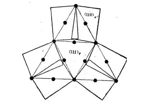
Figure 3 illustrates the crystallographic characteristics of the lath martensite microstructure, as determined by research.
Fig. 3 Schematic diagram of crystallographic characteristics of lath martensite microstructure
A large area composed of lath martensite bundles arranged in parallel is referred to as a lath group and is denoted by A.
A single primary austenite grain can contain several lath groups, typically ranging from 3 to 5.
Each strip group can be divided into multiple parallel regions, such as B shown in the figure.
In some cases, when certain solutions are used for corrosion, only the boundary of the lath group is visible, resulting in a blocky appearance of the microstructure, hence the name blocky martensite.
When color etching techniques are employed, such as 100cc HCl + 5g CaCl2 + 100cc CH3CH solution, black and white tones can be observed within the lath group.
Regions with the same tone correspond to martensite laths with the same orientation, and are referred to as homotropic beams.
According to the Kurdjumov-Sachs (K-S) orientation relationship, martensite can exhibit 24 different orientations in the parent austenite, including six orientations that can generate lath martensite in parallel (refer to Figure 4).
Fig. 4 Martensite (111) in steel γ Possible orientation when forming on the plane
An isopathic bundle refers to a bundle of laths that have been transformed from one of the laths.
Several parallel collinear bundles combine to form a strip group.
Some researchers suggest that within a lath group, only two groups can alternate their positions.
Therefore, a lath group is typically composed of two aligned lath beam groups that alternate with each other, and can also alternate with each other at large angle grain boundaries. However, there are cases where the lath group is mainly comprised of a single type of homotropic bundle, as illustrated in C in Figure 3.
An aligned bundle consists of strips arranged in parallel, as depicted in D in Figure 3.
This scenario can be observed through electron microscopy, as demonstrated in Figure 5.
Fig. 5 Some microstructures in the isotropic beam of lath martensite in Fe-0.2% C alloy (transmission electron micrograph)
According to the research results in Fe-0.2% C alloy, the strip width distribution is a lognormal distribution as shown in Fig. 6.
Fig. 6 Strip distribution of film and replica technology
As observed from the figure, the lath width with the highest occurrence frequency ranges from 0.15 to 0.20μm, and the distribution curve is heavily skewed towards smaller sized laths. However, a small proportion of laths have a width of 1 to 2μm.
Figure 7 illustrates that larger laths are often distributed throughout the lath bundle, which is a key characteristic of the lath bundle microstructure.
Fig. 7 Microstructure of lath martensite in Fe-0.2% C alloy (transmission electron micrograph)
Experimental results indicate that changing the austenitizing temperature alters the austenite grain size but has minimal impact on the width distribution of the lath.
However, the size of the lath group increases as the austenite grain size increases, while the ratio between the two remains approximately constant. Thus, the number of lath groups generated in an austenitic grain typically remains unchanged.
Thin film electron microscopy measurements show that the area of the lath boundary in unit martensite volume is approximately 65000 cm²/cm³.
The area of small angle crystal boundaries in the lath bundle is about 5 times that of large angle crystal boundaries.
In the Fe-Cr-Ni alloy based on 18-8 stainless steel, both lath martensite and ε’-martensite (closely packed hexagonal lattice) can be generated, resulting in a microstructure that differs significantly from that of the Fe-C alloy, as shown in Figure 8.
The structure does not contain lath groups or sympositional bundles; rather, it is created as a thin lath group surrounding a sheet of ε’-martensite (as shown in the parallel strips in the figure).
Nevertheless, the electron microscopic structure of this lath martensite is identical to that found in Fe-C and Fe-Ni alloys.
2. Flake martensite
Another typical martensite structure in iron series alloys is lamellar martensite, which is commonly found in quenched high and medium carbon steels and high Ni Fe Ni alloys.
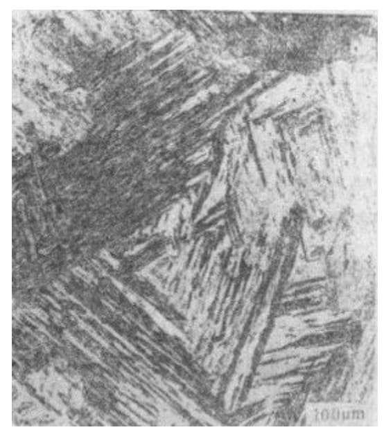
The typical lamellar martensite structure in high carbon steel is shown in Fig. 9.
Fig. 9 Superheated quenching structure of T12A steel 400X (heated at 1000 ℃, water quenched)
This specific type of martensite is known by various names such as lenticular martensite, due to its biconvex lens-like shape. It is also referred to as acicular martensite or bamboo leaf martensite, because when observed under a microscope intersecting with the sample’s grinding surface, it appears as needle-like or bamboo leaf-shaped structures.
The substructure of lamellar martensite is mainly composed of twins, and thus it is also called twin martensite. The microstructure of lamellar martensite is characterized by the fact that the lamellae are not parallel to each other.
When an austenitic grain with uniform composition is cooled to a temperature slightly lower than Ms, the first-formed martensite will run through the entire austenitic grain and divide it into two halves. This limits the size of the martensite formed later, resulting in varying sizes of lamellar martensite. As depicted in Figure 10, the flakes of martensite formed later tend to be smaller.
Fig. 10 Microstructure of lamellar martensite
The size of the flakes almost entirely depends on the grain size of austenite.
Flaky martensite can often be seen with obvious mid ridge (see Fig. 11).
Fig. 11 Flake martensite (with obvious mid ridge, T12 steel is carburized at 1200 ℃ for 5 hours and quenched at 180 ℃)
Currently, the formation rule of mid-ridges is not well-defined.
The habit plane of lamellar martensite is either (225) γ or (259) γ. The orientation relationship with the parent phase is either the Kurdjumov-Sachs (K-S) relationship or the Xishan relationship.
As shown in Figure 12, the martensite contains numerous fine lines that are transformation Luan crystals, while the banded thin ribs in the middle joint part are mid-ridges.
Fig. 12 TEM structure of lamellar martensite
The existence of transformation Lüders crystal is an important feature of lamellar martensite.
The spacing of Lüders crystals is approximately 50 Å and usually does not extend to the boundary of martensite.
The edge of the sheet features a complex dislocation array, which is generally believed to be screw dislocations arranged regularly in the [111] α´ direction.
The transformation Lüders crystal in lamellar martensite is generally a (112)α´ Lüders crystal.
However, in the Fe-1.82% C (c/a=1.08) alloy, a (110) Lüders crystal will mix with a (112)α´ Lüders crystal.
Depending on the internal substructure of the lamellar martensite, it can be divided into the transformation twin area (middle part) centered on the middle ridge and the twin-free area (in the surrounding part of the lamella, there are dislocations).
The proportion of twin zones varies with the alloy composition.
In Fe-Ni alloys, the higher the Ni content (the lower the Ms point), the larger the twin zone.
According to research on Fe-Ni-C alloy, even for an alloy with the same composition, the proportion of the twin zone increases with the decrease of the Ms point (such as caused by changing the austenitizing temperature).
However, the density of transformation twins hardly changes, and the thickness of twins remains about 50 Å.
Lath martensite and lamellar martensite are the two most basic martensite morphologies in steel and alloy.
Their morphological and crystallographic characteristics are listed in Table 1.
Table 1 Types and Characteristics of Martensite in Iron Carbon Alloys
The laths are usually arranged in parallel groups from the austenite grain boundary to the grain interior, and the lath width is usually 0.1~0.2 μ, length less than 10 μ. An austenitic grain contains several lath groups. There are small angle grain boundaries between lath bodies and large angle grain boundaries between lath groups.
The convex lens sheet (or needle, bamboo leaf) is slightly thicker in the middle, the primary one is thicker and longer, and it traverses the austenite grains, while the secondary one is smaller. Between the primary lamellae and the austenite grain boundary, the angle between the lamellae is large, and they collide with each other to form microcracks.
On the same left, there is a middle ridge in the center of the slice, and thin slices with zigzag distribution are common between the two primary slices.
Substructure
Dislocation network (entanglement), dislocation density increases with carbon content, usually (0.3~0.9) × A small amount of fine twins can sometimes be seen at 1012cm/cm3.
The fine twins with a width of about 50 | form the transformation Lie and twin regions with the middle ridge as the center. As the M point decreases, the transformation twin region increases, and the edge of the sheet is a complex dislocation array. The twin plane is (112) α ※, the twin direction is [11I] α ´
Formative process
Cooling nucleation, new martensite sheets (laths) are produced only during cooling
The growth speed is low, and a lath is formed in about 10-4s
The growth speed is high, and a sheet is formed in about 10-7s
There is no “explosive” transformation, and the cooling transformation rate is about 1%/℃ within less than 50% of the transformation amount
When M<0 ℃, there is an “explosive” transformation, and the new martensite sheet does not produce uniformly with the temperature drop, but because of the self triggering effect, it forms in groups (in the shape of “Z”) continuously and massively in a very small temperature range, accompanied by a temperature rise of 20~30 ℃
3. Other martensite morphology
3.1 Butterfly martensite
In Fe Ni alloys or Fe Ni C alloys, when martensite is formed within a certain temperature range, martensite with special morphology will appear, as shown in Fig. 13.
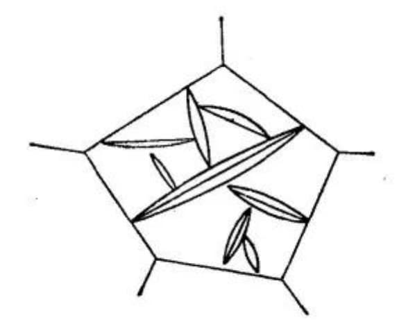
Fig. 13 Microstructure of Dish Martensite
The three-dimensional shape of this martensite is a slender rod, and its section is butterfly-shaped, hence it is called butterfly martensite.
It has been discovered that butterfly martensite forms in Fe-31% Ni or Fe-29% Ni-0.26% C alloy within the temperature range of 0 to -60 ℃.
Electron microscope studies have confirmed that its internal substructure comprises high-density dislocations, with no twins visible.
The crystallographic relationship with the parent phase generally adheres to the K-S relationship. Butterfly martensite primarily forms between 0 to -20 ℃, coexisting with lamellar martensite between -20 to -60 ℃.
It can be observed that, for the two aforementioned alloy systems, the formation temperature range of butterfly martensite lies between the formation temperature range of lath martensite and lamellar martensite.
The joint of two wings of butterfly martensite is very similar to the mid-ridge of lamellar martensite. It is assumed that the martensite (probably twinning) growing from here to the two sides along different orientations will show butterfly shape.
The joint part of butterfly martensite is akin to the joint part of two pieces of martensite formed by an explosion, but it does not contain any twin structure, which is dissimilar to sheet martensite.
From the internal structure and microstructure perspective, butterfly martensite is similar to lath martensite, but it does not occur in rows.
As of now, many aspects of butterfly martensite are still not clear. However, its morphology and properties lie between lath martensite and lamellar martensite, making it an interesting topic to explore.
3.2 Flaky martensite
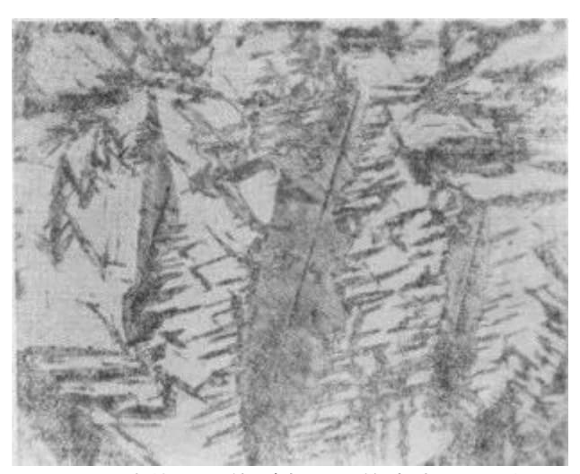
This martensite has been discovered in a Fe-Ni-C alloy that exhibits an exceptionally low Ms point. It appears as a very thin band in three-dimensional form, with the bands crossing each other and displaying twists, branches, and other unique shapes, as depicted in Figure 14c.
Fig. 14 Fe-Ni-C Alloy Cooled to Ms Point
Microstructure of martensite formed at the same temperature
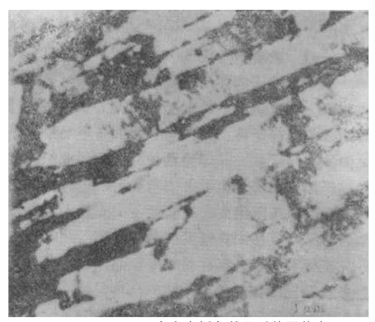
The electron microscopic structure of this martensite is shown in Fig. 15.
Fig. 15 Electron microscopic structure of lamellar martensite (Fe-31%, Ni0.23% C, Ms=- 190 ℃, cooled to – 196 ℃)
The material under examination is a complete Luan martensite made up of (112) α´ Luan crystals without a central ridge, which distinguishes it from lamellar martensite.
It has been observed that the morphology of Fe-Ni-C system martensite changes from lenticular to lamellar as the formation temperature decreases.
In the Fe-Ni-C alloy with a carbon content of approximately 0.25% and Ms = -66 ℃, the structure is explosive lamellar martensite, as depicted in Figure 14a.
As Ms decreases to -150 ℃, a small amount of lamellar martensite starts to appear, as shown in Figure 14b.
At the point where Ms drops to -171 ℃, the entire structure is composed of lamellar martensite (see Figure 14c).
It has been found that the transition temperature from lens sheet to thin sheet increases with the increase of carbon content.
When the carbon content reaches 0.8%, the formation zone of lamellar martensite is below -100 ℃.
As the transformation temperature decreases, during the lamellar martensite transformation, there is not only continuous formation of new martensite sheets, but also thickening of old martensite sheets.
Thickening of old martensite sheets is not visible in lamellar martensite.
3.3 ε’ Martensite
All the martensites mentioned above have either a body-centered cubic (α’) or body-centered square structure.
In alloys with low stacking fault energy in austenite, dense hexagonal lattice ε’ martensite may also form.
This type of martensite is prevalent in high Mn-Fe-C alloys.
However, the 18-8 stainless steel represented by Fe-Cr-Ni alloys often coexists with α’-martensite.
ε’ martensite is also thin, as depicted in Figure 16.
Along the (111) γ surface, widmanstatten formation is observed, with a substructure characterized by numerous stacking faults.
Fig. 16 Martensite Microstructure of Fe-16.4% Mn Alloy (Corrosion by Nitrate Alcohol)
2. Relationship between chemical composition and martensite morphology and internal substructure of alloys
The presence of alloying elements in steel has a crucial impact on the shape of martensite.
A common example is that the martensite shape in Fe-C and Fe-Ni alloys shifts from lath to flake as the alloy content increases. For instance, in the Fe-C alloy, below 0.3% carbon, the martensite is lath-shaped, while above 1% carbon it becomes flake-shaped. In the range of 0.3% to 1.0% carbon, both forms of martensite can be present.
However, different sources may show inconsistent concentrations that trigger the transition from lath to lamellar martensite. This variability is linked to the effect of quenching speed, with a higher quenching speed leading to a lower minimum carbon concentration required for twin martensite formation.
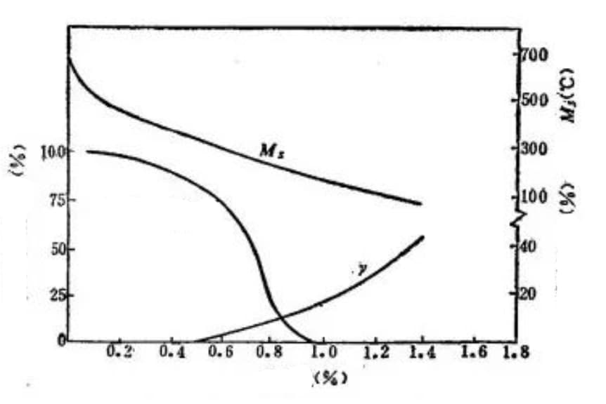
Figure 17 illustrates the impact of carbon content on the type of martensite, the Ms point, and the amount of retained austenite in Fe-C alloys.
Fig. 17 Effect of carbon content on Ms point, lath martensite content and retained austenite content (carbon steel quenched to room temperature)
The figure demonstrates that steel with a carbon content lower than 0.4% contains almost no retained austenite.
As the carbon content increases, the Ms point decreases while the amount of Luan crystal martensite and retained austenite increases.
Table 2 summarizes the relationship between the martensite morphology and the composition of binary iron alloys.
Table 2 Martensite Morphology of Fe Binary Alloys
Alloy system
Lath martensite
Lamellar martensite
Martensite
Alloy composition (%)
Point M (℃)
Alloy composition (%)
Point M (℃)
Alloy composition (5%)
Extended Y-zone
Fe-C
Fe-N
Fe-Ni
Fe-Pt
Fe-Mn
Fe-Ru
Fe-Ir
Fe-Cu
Fe-Co
<1.0
<0.7
<29
<20.5
<14.5
7.5~19
20~48
2~6
0~1
1~24
700~200
700~350
700~25
700~400
700~150
600~200
550~40
–
700~620
620~800
0.6~1.95
0.7~2.5
29~24
24.6
–
–
–
–
–
–
500~40
350~100
25~195
-30
–
–
–
–
–
–
–
–
14.5~27
11~17
35~53
–
–
–
Reduced Y area
Fe-Cr
Fe-Mo
Fe-Sn
Fe-V
Fe-W
<10
<1.94
<1.3
<0.5
<0.3
700~260
700~180
–
–
–
–
–
–
–
–
–
–
–
–
–
–
–
The table demonstrates that all the alloy elements in zone γ are transformed into lath martensite.
As the concentration of alloy elements in the expanded P zone increases, the general Ms point decreases significantly, accompanied by a change in the martensite morphology.
For instance, in binary alloys such as Fe-C, Fe-N, Fe-Ni, Fe-Pt, and others, the martensite morphology transforms from lath to flake with the increase of alloy element content.
However, the addition of Mn, Ru, and Ir can greatly reduce the stacking fault energy of austenite, resulting in a change in martensite morphology from lath to ε´ martensite with an increase in alloy element content in binary iron alloys.
Fe-Cu and Fe-Co alloys are exceptions among the elements in the expanded γ-zone.
Although Cu is part of the expanding Y-zone element, the small amount of solid solution in Fe leads to a relatively stable Ms point, and thus it shows the same tendency as the shrinking Y-zone alloys.
Fe-Co alloy is unique in comparison to other alloys. With an increase in Co content, the Ms point increases, making it a special case.
In general, there are various types of alloy elements in steel, but if a third element is added to Fe-C or Fe-Ni alloy, a small amount will not significantly alter the martensite morphology from that of the binary alloy.
As previously mentioned, Fe-Ni-C alloys can form lath, butterfly, lens sheet, and thin sheet martensite. The relationship between the formation temperature of these four forms of martensite and the carbon content and Ms point is shown in Figure 18.
Fig. 18 Relationship between martensite morphology, carbon content and Ms point of Fe-Ni-C alloy
The figure displays that the formation temperature of lenticular and lamellar martensite increases as the carbon content increases.
The figure also highlights the formation area of butterfly martensite with a hatched area.
Table 3 summarizes the relationship between the morphology, substructure, and crystallographic characteristics of martensite in iron-based alloys.
Table 3 Characteristics of Fe System Martensite
Habitual surface
orientation relationship
Martensite morphology
Second shear type
Substructure in martensite
M. Point
Austenite fault energy
Steel grade
(111) (225)(259)
K-S K-S Xishan
Lath
Slip twin
Dislocation
High medium low
Low low or medium high
Low carbon copper, high Mn steel, low Ni steel; high and medium carbon steel, stainless steel, medium Ni steel; high Ni steel, extremely high carbon steel
In steel, martensite with a carbon content of less than 0.20% is generally considered to have a body-centered cubic lattice structure. Martensite with a carbon content greater than 0.20% is considered to have a body-centered tetragonal lattice structure.
It is commonly believed that body-centered cubic martensite in low carbon steel is equivalent to dislocation martensite, while body-centered tetragonal martensite is equivalent to high carbon twin martensite. However, in Fe-Ni alloys, twin martensite can also have a body-centered cubic structure.
As a result, the relationship between crystal structure and substructure remains uncertain.
3. Factors affecting the morphology and substructure of martensite
The discussion above covers the law of the change in martensite morphology due to a change in alloy composition.
Currently, there is much debate on the factors that impact this change and there is no clear consensus.
It is widely believed that morphological changes are essentially changes in the substructure, and common perspectives include:
1. Ms point
Advocates of this viewpoint believe that the morphology of martensite is dependent on the Ms temperature.
They contend that in Fe-C alloys, an increase in carbon content results in a decrease in the Ms temperature.
At temperatures below a certain range (300-320℃), it becomes easier to form transformation twins and resultant lamellar martensite.
Table 4 outlines the relationship between the martensite morphology, the crystal characteristics of carbon steel, and the carbon content and Ms temperature.
Table 4 Relationship between martensite morphology and crystallographic characteristics of carbon steel and carbon content and Ms point of steel
Carbon content (%)
Crystal structure
Orientation relationship
Habitual surface
M. Point (℃)
Martensite morphology
<0.3
Body centered cubic or square
K-S relationship
(111)
>350
Lath martensite
0.3~1.0
Centroid square
K-S relationship
Strip (111), sheet (225)
350~200
Mixed martensite
1.0~1.4
Centroid square
K-S relationship
(225)
<200
Flake martensite with partial twins and dislocations in substructure
1.4~1.8
Body · Heart Square
Xishan relationship
(259)
<100
Typical lamellar martensite with obvious mid ridge and “Z-shaped” arrangement
The transformation of martensite morphology from lath to flake with decreasing Ms point can be explained as follows:
Table 4 demonstrates a correlation between the habit surface and martensite morphology. The formation temperature of low-carbon martensite is generally believed to be high, with the (111) γ plane as the habit plane due to its large shear. At these high temperatures, slip is easier to occur than twinning and there are fewer (111) γ crystal systems in the face centered cubic lattice, resulting in a limited number of initial orientations for martensite formation, leading to the formation of clustered martensite within the same austenite.
As the temperature of the Ms point decreases, twinning becomes easier to occur than slip, and the habit plane shifts to (225) γ or (259) γ. This shift results in an increased number of crystal systems and initial orientations for martensite formation, leading to the formation of Li crystal lamellar martensite with adjacent sheets not being parallel to each other within the same austenite.
It has been established that high-temperature martensite formation cannot result in twin lamellar martensite, even if the austenite is significantly strengthened. The Ms point in Fe-Ni-C alloys can be altered by changing the austenitizing temperature, allowing for the attainment of different Ms points within the same alloy.
When the cooling temperature is slightly lower than the corresponding Ms point, the change in martensite morphology from butterfly shape to sheet shape can be observed. Additionally, the decrease in the formation temperature leads to an increase in the transformation twin zone.
The morphology of deformation-induced martensite formed in the same alloy at various temperatures above the Ms point was also studied, revealing that the martensite morphology changes with the change in deformation temperature (i.e. the formation temperature of deformation-induced martensite). These findings confirm that the martensite morphology and internal structure of this type of alloy are solely related to the Ms point.
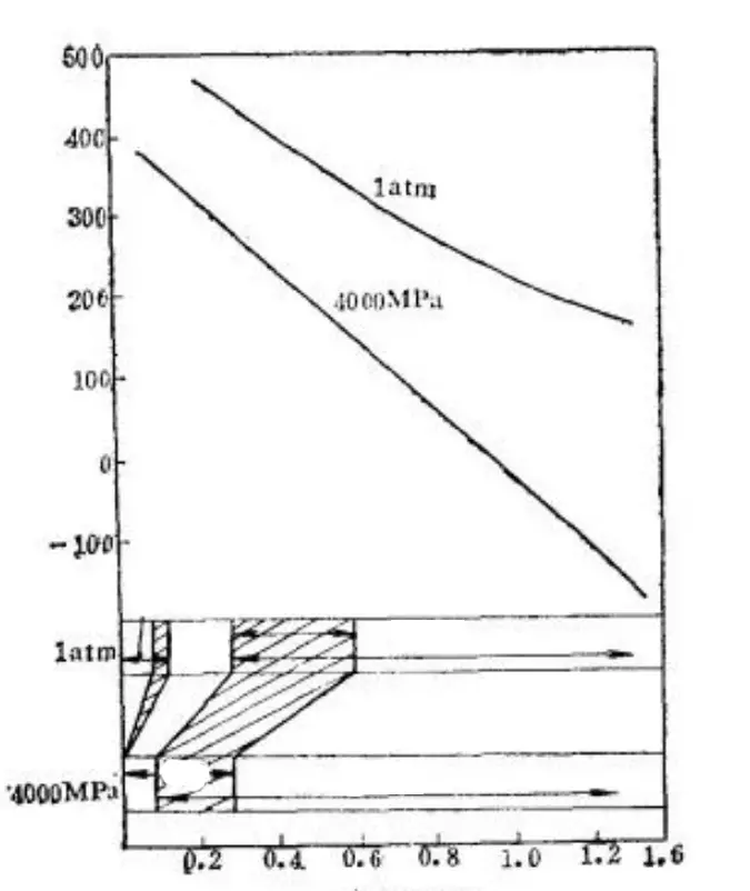
Furthermore, under high pressure and decreasing Ms point, transformation twins become more likely to occur, leading to a change in martensite morphology from lath to sheet, as shown in Fig. 19. This experimental evidence supports the significance of the Ms point.
Fig. 19 Effect of 4000MPa Pressure on Ms Point and Martensite Substructure of Ferromagnetic Alloy
In the actual formation process, multiple martensites are produced consecutively at varying temperatures between the Ms and Mf points.
The temperature at which each martensite crystal forms is unique, thus the internal structure and morphology of each martensite crystal are also distinct.
Therefore, it is more accurate to state that the formation temperature, rather than the Ms point, affects the morphology and internal structure of martensite.
2. The stacking fault energy of austenite
According to Kelly et al., they propose a hypothesis that states the lower the stacking fault energy of austenite, the more challenging it becomes to produce the transformation to bainite crystals, and the more likely it is to form lath martensite.
Both 18-8 stainless steel and Fe-8% Cr-1.1% C alloy have low stacking fault energies. At liquid nitrogen temperature, dislocation martensite is formed. This phenomenon is difficult to explain using the Ms Point hypothesis, but it can be accounted for by this hypothesis.
Furthermore, in the lamellar martensite of Fe-30~33% Ni alloy, the transformation twin zone increases as the Ni content increases. As Ni is known to increase the stacking fault energy of austenite, this experimental phenomenon supports the hypothesis.
It is worth noting that this experimental phenomenon can also be explained by the Ms Point theory, as Ni decreases the Ms Point.
3. Strength of austenite and martensite
Recently, Davis and Magee proposed a hypothesis regarding the relationship between the strength of austenite and the morphology of martensite. They used an alloying method to alter the strength of austenite and studied the resulting changes in martensite morphology.
The results revealed that the martensite morphology changes based on the strength of the austenitic yield strength at the Ms point, which is approximately 206MPa. Above this boundary, lamellar martensite with a habit plane of {259} γ is formed. Below this boundary, either lath martensite with a habit plane of {111} γ or lamellar martensite with a habit plane of {225} γ is formed.
As a result, Davis and Magee believe that the strength of austenite is the main factor that affects the morphology of martensite. They also further investigated the strength of martensite. When the strength of austenite is lower than 206MPa, if the strength of the resulting martensite is high, it forms as {225}γ martensite. If the strength of martensite is low, {111}γ martensite is formed.
This hypothesis can be applied to explain the morphological changes resulting from changes in alloy composition or Ms point, particularly the transformation of {111}γ to {225}γ in Fe Ni alloys and {111}γ to {225}γ to {259}γ in Fe-C alloys.
Additionally, the hypothesis provides a clear understanding of the formation of {225}γ martensite, which was not well defined in the past. It is formed when weak austenite transforms into strong martensite.
While carbon has limited effects on the strengthening of austenite, it has a significant impact on the strengthening of martensite. {225}γ martensite mostly occurs in alloy systems with high carbon content.
This hypothesis is based on the following:
If the relaxation of transformation stress in martensite occurs solely through twinning deformation, the resulting martensite will have the habit plane {259} γ.
When the relaxation of transformation stress is carried out partially in the austenite through slip mode and partially in the martensite through twinning mode, the martensite will have the habit plane {225} γ.
If martensite also undergoes sliding mode, the habit plane will be {111} γ.
Experimental results suggest that this hypothesis is partially correct, but further research is still needed in the future.
It should be noted that the strength of austenite and martensite as outlined in this hypothesis is closely related to various factors such as alloy composition, type, Ms point, austenitic stacking fault energy, and others. Therefore, this hypothesis cannot be considered isolated.
4. Critical shear stress of martensite slip and twin deformation
This hypothesis emphasizes that the internal structure of martensite is primarily determined by the mode of deformation during transformation, which is primarily controlled by the critical shear stress of either slip or twin.
Figure 20 illustrates the effect of the critical shear stress of martensite slip or twin and the temperature of Ms and Mf on the formation of martensite morphology.
Fig. 20 Schematic Diagram of the Influence of Critical Shear Stress and Ms Mf Temperature on Martensite Morphology Caused by Martensite Slip or Twin
The arrows in the figure represent the potential directions of movement for the corresponding lines, which are caused by changes in the alloy composition. The movement of the lines leads to the movement of the intersection of the slip twin curves.
From the figure, it can be observed that for low carbon steel (where the Ms and Mf points are both high), the critical shear stress required for slip is less than that required for twinning, resulting in the formation of lath martensite with a high density of dislocations. Conversely, for high carbon steel (where the Ms and Mf points are both low), the critical shear stress required for twinning is small, resulting in the formation of lamellar martensite with a large number of twins.
In the case of medium carbon content, the Ms and Mf points are as shown in the figure. During the martensitic transformation, lath martensite forms first, followed by lamellar martensite. This results in a mixed structure of both types of martensite.
While this view appears to be fundamentally correct, the factors that cause changes in shear stress and how the alloy composition or Ms point influences the critical shear stress for martensitic slip or twinning are still not clear.
Some believe that the increase in transformation driving force leads to the transformation to lamellar martensite. For Fe-C alloys, the limit of the driving force for the change in martensite morphology is 1318 J/mol, and for Fe-Ni alloys, it ranges from 1255 to 1464 J/mol. Others believe that the increase in C and N content in martensite, causing ordering, is closely related to morphological transformation.
4. Formation of lamellar martensite microcracks in Fe-C alloy
When high carbon steel is quenched, it is susceptible to the formation of microcracks in the martensite.
Previously, it was thought that these microcracks were a result of microstress caused by the expansion of volume during the martensitic transformation.
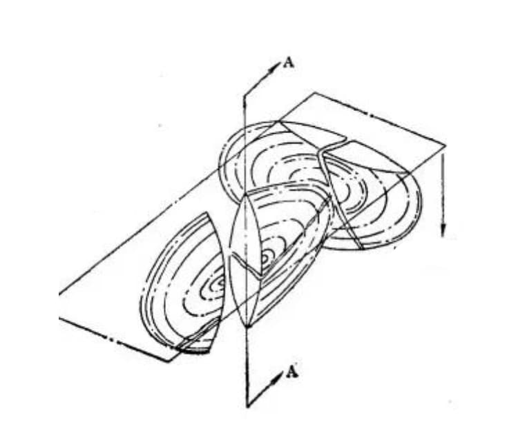
However, recent metallographic observations have revealed that the formation of microcracks is actually due to the collision of growing martensite, as illustrated in Figure 21.
Figure 21. Schematic diagram of microcracks formed by the collision of two Fe-C martensite sheets. (Section A-A represents the cross-section of one martensite sheet, which has diffused into two martensite sheets.)
The formation of martensite occurs rapidly. When martensite sheets collide with each other or with an austenite grain boundary, a significant stress field is generated due to the impact.
Because high-carbon martensite is extremely brittle and cannot be relieved through slip or twin deformation, it is prone to forming impact cracks.
This inherent defect increases the brittleness of high-carbon martensite steel.
Under the influence of other stressors, such as thermal stress and structural stress, microcracks will grow into macrocracks.
The presence of microcracks will also significantly reduce the fatigue life of components.
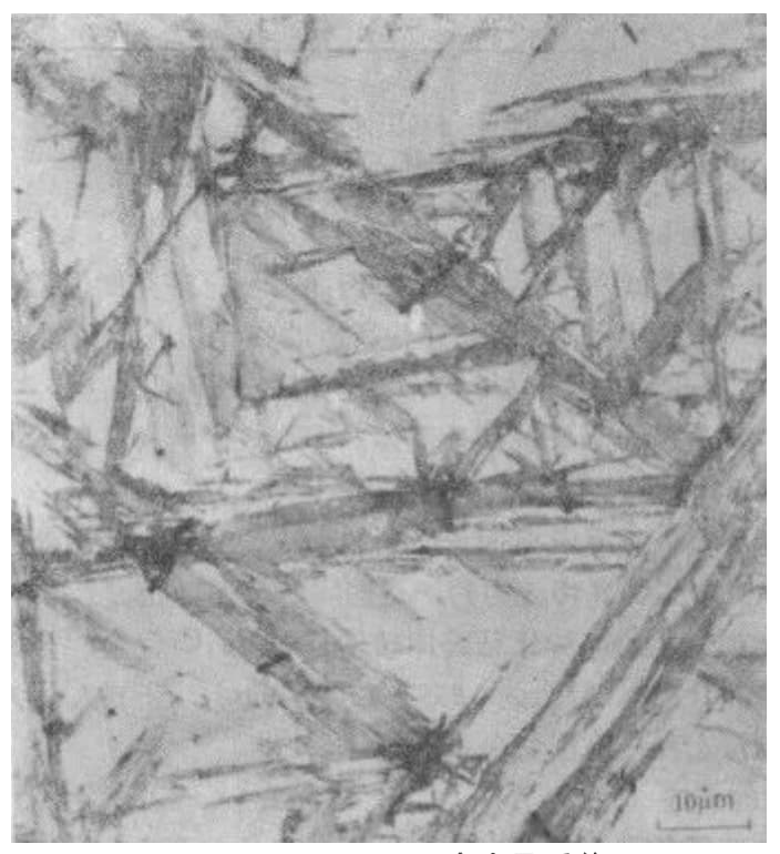
Microcracks in the lamellar martensite of the Fe-C alloy often occur at the junction of several radial martensite needles or within the martensite needles, as illustrated in Figure 22.
Fig. 22 Optical microscopic characteristics of microcracks in martensite of Fe-1.39% C alloy
The sensitivity of microcrack formation in martensite is generally expressed in terms of the area of microcracks per unit volume of martensite (Sv).
Experimental evidence suggests that the sensitivity of martensite to microcrack formation is influenced by several factors, including:
1. Effect of quenching cooling temperature
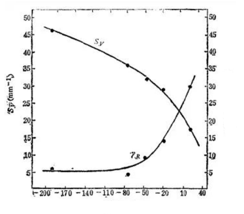
With the decrease in quenching cooling temperature, the amount of retained austenite (represented by γR) in the quenched steel structure decreases, resulting in an increase in the amount of martensite and sensitivity to microcrack formation, as depicted in Figure 23.
Fig. 23 Relationship between Fe-C martensite formation microcrack sensitivity and quenching temperature (1.39% C, heated at 1200 ℃ for 1 hour)
2. Effect of martensite transformation amount
Figure 24 illustrates the relationship between the amount of martensite transformation and the susceptibility to microcrack formation.
Fig. 24 The relationship between the micro crack sensitivity (SV) of martensite formation in Fe-1.86% C alloy and the average volume (V) of each piece of martensite, the number of martensite sheets in unit volume (NV) and the transformation of martensite:
According to the figure, the sensitivity to microcrack formation (Sv) increases with the increase of martensite transformation variable, however, when the transformation fraction (f) exceeds 0.27, Sv does not continue to increase.
Even though the number of martensite in unit volume (Nv) increases, the size of the martensite sheet formed, represented by the average volume (V) of a piece of martensite, decreases due to continuous division of austenite.
Thus, the size of martensite sheet (V) may have a critical value that affects the sensitivity (Sv) to microcrack formation. If V exceeds this critical value, the sensitivity to microcrack formation (Sv) increases with the increase of transformation fraction.
In conclusion, the formation of cracks is predominantly determined by the size of martensite sheets. While the total number and area of cracks may increase with the increase of martensite transformation variable, the large martensite flakes formed at the early stage result in the majority of cracks being formed during the early stages of transformation.
3. Effect of martensite sheet length
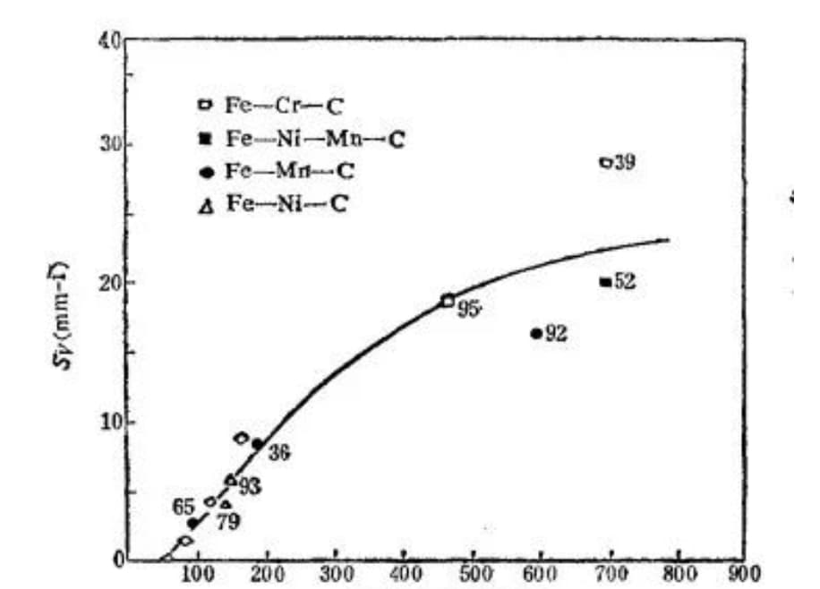
The experiment shows that as the length of the martensite sheet increases (i.e. the maximum size of the sheet grows), the susceptibility of martensite to microcrack formation also increases, as depicted in Figure 25.
Fig. 25 Relationship between the sensitivity of microcrack formation and the length of martensite sheet (the number beside the point is the martensite content%)
Long martensite sheets are more susceptible to impact from other martensite sheets due to their size. Additionally, they tend to intersect with austenite grains, increasing the likelihood of encountering grain boundaries.
Experiments have shown that microcracks are predominantly formed in coarse martensite, whereas fine martensite rarely results in the formation of microcracks.
As a result, there is likely a critical martensite size for the occurrence of microcracks in martensite. Similarly, if the composition of the austenite is relatively uniform, there will be a critical austenite grain size below which microcracks will not occur.
The idea that fine austenite grains can reduce microcracks in quenched high carbon steel has been implemented in production. However, it remains unclear whether the sensitivity to microcracks depends on the size of the martensite sheet itself or the stress field generated by the growth of martensite sheets of the critical size.
4. Effect of austenite grain size
In the case of homogeneous austenite, the length of the martensite sheets formed at the initial stage is linked to the size of the austenite grains. Coarse austenite grains result in the formation of coarse martensite, which is more prone to microcrack formation.
Experimental results, as shown in Figure 26, support this idea. The results indicate that high carbon steel is more prone to cracking when quenched at higher temperatures.
Therefore, it is generally recommended to select a lower quenching temperature for the quenching of high carbon steel.
Fig. 26 Effect of Austenite Grain Size of Carbon Steel (1.22% C) on Field Microcrack Sensitivity
5. Effect of carbon content in martensite
The effect of carbon content on microcrack formation in martensite is demonstrated in Figure 27.
Fig. 27 Effect of carbon content in martensite on microcrack sensitivity
It can be seen from Figure 27 that the likelihood of microcrack formation increases as the carbon content in martensite increases.
However, if the carbon content in austenite is greater than 1.4%, the susceptibility to microcrack formation decreases. This is related to the crystal’s habit plane during the martensitic transformation.
When the carbon content in the steel exceeds 1.4%, the shape of the martensite changes. The sheets become thicker and shorter, the angle between the martensite sheets becomes smaller, and the impact force and stress are reduced. As a result, the sensitivity to microcrack formation decreases.
Table 5 shows that the sensitivity to microcrack formation in 1.39% carbon steel decreases significantly with decreasing carbon content in martensite. The data is presented for a grain size of 3.
A1~Aw temperature (℃)
Carbon content in martensite (%)
Retained austenite (%)
Carbide quantity (%)
Sensitivity to microcrack formation S. (mm-1)
1010
910
871
857
834
799
768
732
1.39
1.30
1.21
1.18
1.05
1.01
0.92
0.83
33.5
22
15
13
12
8
9
6
3.9
6
6.5
12
15
17.5
20
18
17
13
9
10
4.5
1.5
0.15
Metallographic analysis indicates that the reduction in microcrack sensitivity is associated with the presence of more parallel growth lath martensite in the microstructure.
Lath martensite has high plasticity and toughness, and the risk of mutual impact is reduced due to the parallel growth of the lath martensite, leading to low sensitivity to microcracks.
As previously mentioned, high carbon steel is susceptible to cracking due to its coarse austenite grain structure and high carbon content in martensite. To mitigate this, the production process tends to use lower heating temperatures and shorter holding times to decrease the carbon content in martensite and achieve finer grains.
In general, hypereutectoid steels, which undergo incomplete quenching, produce cryptocrystalline martensite, which is less prone to microcracking. This is why they have excellent overall properties.
As the founder of MachineMFG, I have dedicated over a decade of my career to the metalworking industry. My extensive experience has allowed me to become an expert in the fields of sheet metal fabrication, machining, mechanical engineering, and machine tools for metals. I am constantly thinking, reading, and writing about these subjects, constantly striving to stay at the forefront of my field. Let my knowledge and expertise be an asset to your business.
Have you ever wondered how the heat treatment of steel can transform its properties? This article dives into the fascinating world of 45 steel, exploring how annealing and normalizing affect…
Have you ever wondered how the hidden process of heat treatment transforms ordinary carbon steel into a versatile material for mechanical parts? This blog delves into the fascinating world of…
Why does steel change its structure under different conditions? This article explores the five critical factors that influence the martensite start (Ms) point in steel. From chemical composition and deformation…
Have you ever wondered what happens to steel as it cools? In this article, we explore the fascinating transformations that occur, such as the Widmanstatten and Martensite structures. You'll learn…
Have you ever wondered what makes construction machinery so durable? The secret lies in the remarkable 35MnB steel. This article unveils how elements like Carbon, Silicon, Manganese, Boron, and Chromium…
Have you ever wondered why steel sometimes fails unexpectedly? In this illuminating blog post, we'll dive deep into the fascinating world of steel defects. As an experienced mechanical engineer, I'll…
Have you ever wondered about the different types of stainless steel and their applications? In this blog post, we'll dive into the world of stainless steel grades, exploring their unique…
Ever wondered how stainless steel can be both strong and resistant to corrosion? This article unravels the mystery behind PH stainless steel, a material that benefits from precipitation hardening. You'll…
Have you ever wondered why stainless steel is so widely used in engineering and manufacturing? This article explores the eight critical mechanical properties that make stainless steel indispensable: yield strength,…