Unveiling the Transformation of Steel Cooling: Widmanstatten vs. Martensite
Have you ever wondered what happens to steel as it cools? In this article, we explore the fascinating transformations that occur, such as the Widmanstatten and Martensite structures. You’ll learn how these changes impact the steel’s properties and why they matter in real-world applications. Get ready to uncover the secrets behind steel’s strength and durability!
Transformation of Steel During Cooling – Widmanstatten
1. Formation of Widmanstatten structure
In actual production, hypoeutectoid steel with a carbon content (ωc) less than 0.6% and hypereutectoid steel with a carbon content greater than 1.2% are cooled by air after casting, hot rolling, and forging. The weld seam or heat-affected zone is cooled either by air or, when the temperature is too high, rapidly cooled. This results in the growth and precipitation of pre-eutectoid ferrite or pre-eutectoid cementite from the austenite grain boundary along certain crystal planes of austenite, in a needle-like manner.
2. Microstructure of Widmanstatten structure
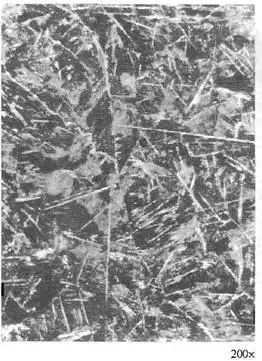
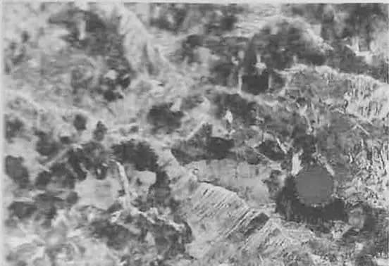
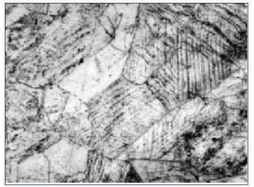
Under a metallographic microscope, the presence of nearly parallel or regularly arranged acicular ferrite or cementite and the pearlite structure between them can be observed. This structure is referred to as Widmanstätten, and the following figure illustrates the Widmanstätten of ferrite and cementite.
3. Formation mechanism of Widmanstatten structure
The Widmanstatten ferrite is formed through a shear mechanism, similar to the process in Bainite. This results in a convex sample.
Due to the high cooling rate during formation, ferrite can only precipitate along a specific crystal surface of austenite and has a crystal orientation relationship with its parent phase, austenite.
The formation of acicular ferrite can occur directly from austenite or network ferrite can be precipitated along the grain boundaries of austenite and grow into the crystal in parallel.
As the Widmanstatten ferrite forms, carbon diffuses from the ferrite into the parent phase, austenite, on both sides, causing the carbon content of the austenite between the ferrite needles to continuously increase and eventually turn into pearlite.
Widmanstatten ferrite formed through the Bainite transformation mechanism is actually carbon-free Bainite.
4. Influencing factors
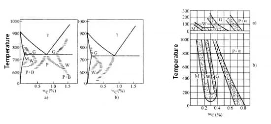
The formation of the Widmanstatten structure is dependent on the carbon content, grain size of austenite, and cooling rate (transformation temperature) in steel.
The following figure illustrates the formation temperature and range of carbon content for various ferrite and cementite. As seen in the figure, the Widmanstatten structure (W zone) can only form under relatively fast cooling rates and within a specific range of carbon content.
For hypoeutectoid steel, if the mass fraction of carbon exceeds 0.6%, it becomes difficult to form the Widmanstatten structure due to its high carbon content and low probability of forming a carbon-poor zone.
Research shows that for hypoeutectoid steel, the Widmanstatten structure can only form when the carbon content is within a narrow range of ωc = 0.15% to 0.35% and the cooling rate is fast, with a fine austenite grain size.
The finer the austenite grain, the easier it is to form network ferrite, but not the Widmanstatten structure. On the other hand, the coarser the austenite grain, the easier it is to form the Widmanstatten structure and the range of carbon content required to form it becomes wider.
Thus, the Widmanstatten structure is typically observed in steel with a coarse austenite grain structure.
5. Properties of Widmanstatten structure
(1) Widmanstatten is a type of superheated structure in steel that can have a negative impact on the steel’s mechanical properties. This includes a reduction in impact toughness and plasticity, as well as an increase in the brittle transition temperature, making the steel more prone to brittle fractures.
(2) It is widely recognized that the strength and impact toughness of steel are significantly reduced only when the austenite grain is coarsened, a coarse ferrite or cementite Widmanstatten structure appears, and the matrix is seriously fragmented.
However, when the austenite grain is relatively fine, even if there is a small amount of acicular ferrite Widmanstatten structure present, the mechanical properties of the steel will not be significantly impacted. This is due to the finer substructure and higher dislocation density of ferrite in the Widmanstatten structure.
(3) The reduction of mechanical properties in steel due to the Widmanstatten structure is always related to the coarsening of austenite grains. If the Widmanstatten structure appears in steel or cast steel and reduces its mechanical properties, the first step is to consider if it is caused by the coarsening of the austenite grain due to high heating temperatures.
(4) For steels that are prone to the Widmanstatten structure, it can be prevented or eliminated through proper control of the rolling process, reducing the final forging temperature, controlling the cooling rate after forging, or changing the heat treatment process such as quenching and tempering, normalizing, annealing, or isothermal quenching to refine the grain.
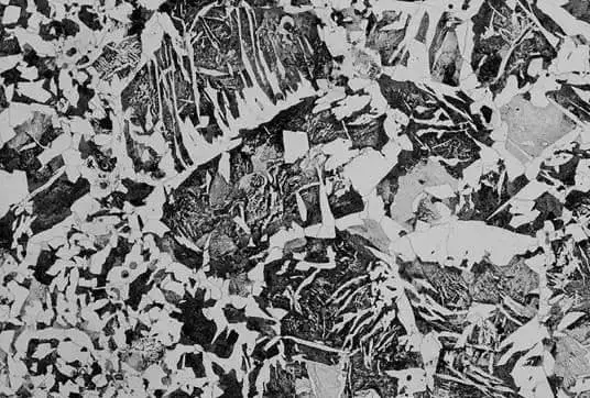
6. Appreciation of Widmanstatten structure
Transformation of Steel During Cooling – Martensite
Structure, structure and properties of martensite crystal
1. Definition
(1) Martensitic Transformation: The non-diffusive phase transformation that takes place when steel is rapidly cooled from the austenitic state to prevent its diffusive decomposition (below the MS point) is known as the martensitic transformation.
It is important to note that the transformation is characteristic of martensite and the transformation products are all referred to as martensite.
(2) Martensite: In essence, martensite in steel is an interstitial solid solution where carbon is supersaturated in α-Fe.
The martensitic crystal structure can take on the following forms:
Body-centered cubic: This is the crystal structure of martensite found in low-carbon steel or carbon-free alloys.
Body-centered tetragonal: This is the crystal structure of martensite found in steels with a high carbon content.
Hexagonal lattice: This is the crystal structure of martensite found in complex iron-based alloys at low temperatures.
Schematic diagram of body centered square lattice of martensite
3. Microstructure of martensite
There are two basic forms of martensite in steel: lath martensite (dislocation martensite) and lamellar martensite (also known as needle martensite).
(1) Lath Martensite
Lath martensite is a common martensitic structure found in low-carbon steel, medium-carbon steel, maraging steel, stainless steel, and other iron-based alloys.
Low carbon martensite 500×
a) Structural morphology: martensite lath (D) → martensite bundle (B-2; C-1) → lath group (3-5) → lath martensite.
Schematic diagram of slat martensite microstructure
b) The dense laths are usually separated by residual austenite with high carbon content.
The presence of this thin layer of residual austenite can significantly improve the mechanical properties of the steel.
Fig. thin film transmission structure of slat martensite
c) There are a large number of dislocations in lath martensite, and the distribution of these dislocations is not uniform.
It forms a cellular substructure, called dislocation cell, so it is also called dislocation martensite.
(2) Lamellar Martensite
Lamellar martensite is found in high-carbon steel (ωC > 0.6%), nickel (ωNi = 30%) stainless steel, and some non-ferrous metals and alloys.
(a) Structural Morphology: The spatial morphology of lamellar martensite is in the form of a convex lens.
Due to the cutting of the sample during polishing, its cross-section appears needle-like or bamboo-leaf-like under the optical microscope.
Therefore, lamellar martensite is also known as needle-like martensite or bamboo-leaf-like martensite.
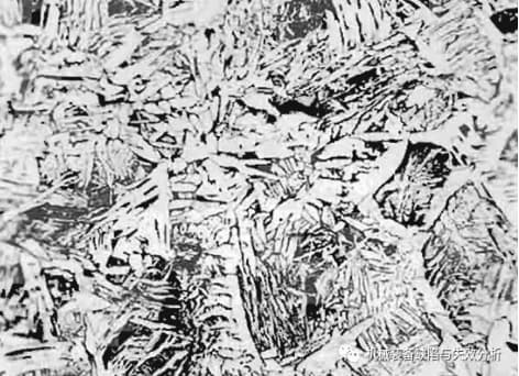
High carbon martensite
(b) Microstructure Characteristics: The martensite sheets in lamellar martensite are not parallel to each other.
In an austenite grain, the martensite formed by the first sheet often spans the entire austenite grain and is split into two parts, causing the size of the martensite sheets formed later to become smaller and smaller.
High carbon lamellar martensite
(c) Size: The maximum size of the lamellar martensite depends on the original size of the austenite grain. The larger the austenite grain, the coarser the martensite sheet.
(d) Cryptocrystalline Martensite: When the largest piece of martensite is too small to be distinguished by an optical microscope, it is referred to as “cryptocrystalline martensite.”
The martensite obtained through normal quenching in production is generally in the form of cryptocrystalline martensite.
Cryptocrystalline martensite
(e) Substructure: The substructure of lamellar martensite is primarily twinned, which is why it is also referred to as twin martensite.
The twins are typically located in the center of the martensite and do not extend to the edge region of the martensite sheet. The edge region contains high-density dislocations.
In steel with a carbon content of ωC > 1.4%, a fine twin region with high density can be seen in the middle ridge line of the martensite sheet.
(f) Microcracks: The rapid formation of martensite generates a considerable stress field when it collides with other martensite or austenite grain boundaries.
Lamellar martensite is hard and brittle, and the stress cannot be relaxed by sliding or twin deformation, making it susceptible to impact cracks.
In general, the larger the austenite grain and the larger the martensite sheet, the more microcracks will form after quenching. The presence of microcracks increases the brittleness of high-carbon steel parts.
Under the influence of internal stress, the microcracks will eventually expand into macro cracks, leading to cracking of the workpiece or a noticeable reduction in its fatigue life.
(g) Morphology: The morphology of martensite is primarily dependent on the carbon content of austenite and is related to the martensite transformation start temperature (MS point) of the steel.
The higher the carbon content of austenite, the lower the MS and MF points.
Carbon content
Shape
Formation temperature (general)
ωC<0.2%
lath martensite
Above 200 ℃
ωC>0.6%
plate martensite
Below 200 ℃
ωC=0.2%~1%
Lath and sheet mixed structure
The board horse is formed first, and then the piece horse is formed
(h) Influence of Elements on Martensite Morphology: Elements such as Cr, Mo, Mn, and Ni (which lower the MS point) and Co (which raises the MS point) all increase the likelihood of forming lamellar martensite.
4. Properties of martensite
(1) Mechanical Properties: Martensite is characterized by high strength and hardness.
(2) Effect of Carbon Content on Properties: The hardness of martensite mainly depends on its carbon content.
When ωC < 0.5%, the hardness of martensite rises steeply with increasing carbon content.
However, when ωC > 0.6%, although the hardness of martensite increases, the hardness of the steel decreases due to the presence of a higher amount of residual austenite.
(3) Influence of Alloying Elements: Alloying elements have a minimal effect on the hardness of martensite, but they can enhance its strength.
(4) Hardness: Martensite has varying levels of hardness and strength, which are primarily achieved through solution strengthening, phase transformation strengthening, and aging strengthening.
The details are as follows:
Solid Solution Strengthening: The presence of interstitial atoms in the octahedral gap of the α-phase lattice creates a square distortion in the lattice, which generates a stress field.
This stress field strongly interacts with dislocations, thus enhancing the strength of martensite.
Phase Transformation Strengthening: During the transformation to martensite, high-density lattice defects are formed in the crystal. The high-density dislocations in lath martensite and the twins in lamellar martensite inhibit dislocation movement, thereby strengthening martensite.
Aging Strengthening: After the formation of martensite, the carbon and alloy elements atoms diffuse, segregate, or precipitate to dislocations or other lattice defects, pinning dislocations and making it more difficult for dislocations to move, thereby strengthening martensite.
(5) Martensite Strength: The smaller the size of the martensite lath group or sheet, the higher the strength of martensite. This is because the phase interface of martensite impedes dislocation movement, and the smaller the original austenite grain, the higher the strength of martensite.
The plasticity and toughness of martensite depend primarily on its substructure. Twin martensite has high strength, but low toughness, while dislocation martensite has both high strength and good toughness.
(6) Martensite Volume: Among the various structures in steel, austenite has the smallest specific volume and martensite has the largest specific volume.
Thus, the volume expansion of steel during quenching is a major factor in generating large internal stress, deformation, and even cracking in the workpiece.
Characteristics of martensite transformation
The driving force behind martensite transformation, like other solid phase transformations, is the chemical free energy difference per unit volume between the new phase (martensite) and the parent phase (austenite). The resistance to this phase change is also influenced by the interface energy and strain energy generated during the formation of the new phase.
Despite the presence of a coherent interface between austenite and martensite, the interface energy is small. The large coherent strain energy, caused by the significant difference in specific volume between martensite and austenite and the need to overcome shear resistance and generate numerous lattice defects, leads to increased elastic strain energy and large resistance to the transformation of martensite. As a result, a sufficient undercooling is required to ensure that the transformation driving force surpasses the transformation resistance, allowing for the transformation from austenite to martensite to occur.
The starting temperature of martensite transformation, denoted as “ms,” is defined as the temperature at which the free energy difference between martensite and austenite reaches the minimum driving force required for transformation.
Martensite transformation is a transformation of undercooled austenite that occurs at low temperatures.
Compared to pearlite transformation and bainite transformation, martensite transformation has the following distinct features:
Non-diffusive Nature of Martensite Transformation
Martensite transformation occurs when austenite is undercooled. At this time, the activity of iron atoms, carbon atoms, or alloy elements is very low, so the transformation takes place without diffusion. There is only a reconstruction of lattice rules, and there is no change in composition between the new phase and the parent phase.
Shear Coherence of Martensite Transformation
Shear refers to the deformation caused by two parallel forces that are close, equal in size, and opposite in direction, acting on the same object. During martensite transformation, the upper surface of the pre-polished specimen inclines and becomes convex, which demonstrates that the transformation of martensite is directly related to the macroscopic properties of the parent phase and that martensite is formed through shear.
Martensite and its parent phase, austenite, remain coherent, with atoms at the interface belonging to both martensite and austenite. The phase interface is a shear-coherent grain boundary, also known as a habit plane.
Martensite transformation is a phase transformation process in which the new phase is formed on specific crystal and habit planes of the parent phase and maintains coherence through the shearing of the parent phase.
Martensite Transformation Occurs Within a Temperature Range
Nucleation of Martensite
Martensite nucleation is not uniform throughout the alloy, but occurs in favorable positions within the parent phase, such as lattice defects, deformation regions, or carbon-poor regions.
Martensitic Transformation Process
Like other solid-state phase transitions, martensite transformation also occurs through nucleation and growth. The transformation is a short-range migration of atoms, and after the formation of a crystal nucleus, the growth rate is very fast (102 to 106mm/s) and remains high even at low temperatures.
Martensite Transformation Rate
The rate of martensite transformation is determined by the nucleation rate and terminates when all nuclei larger than the critical nucleation radius are exhausted. The greater the undercooling, the smaller the critical nucleation size. Further cooling is needed for the smaller nuclei to nucleate and grow into martensite.
For general industrial carbon steel and alloy steel, martensite transformation occurs during continuous (variable temperature) cooling. The austenite in the steel is cooled below the MS point at a speed greater than the critical quenching speed, resulting in immediate formation of some martensite. The transformation has no incubation period, and with the decrease of temperature, additional martensite is formed, with the first formed martensite not growing. The martensitic transformation increases as the temperature decreases.
Relationship between martensite transformation and temperature
The amount of martensite transformation is solely determined by the temperature reached during cooling and is not influenced by the holding time.
Retained Austenite
If the Ms point of high carbon steel and many alloy steels is above room temperature and the Mf point is below room temperature, a significant amount of untransformed austenite will remain after quenching and cooling to room temperature, known as retained austenite.
To fully transform the retained austenite, it can be subjected to “cold treatment,” such as being placed in liquid nitrogen.
Factors affecting the amount of retained austenite include higher carbon content and the presence of elements that reduce MS.
Mechanical Stabilization of Retained Austenite
Mechanical stabilization of austenite refers to the stabilization phenomenon caused by large plastic deformation or compressive stress during quenching. Retained austenite is related to mechanical stabilization. The austenite surrounded by martensite is in a compressed state and unable to transform, leading to its retention.
Plastic deformation of austenite above the MS point can result in martensite transformation. The greater the amount of deformation, the greater the amount of martensite transformation. This is referred to as deformation-induced martensite transformation.
Reversibility of Martensite Transformation
Reversibility refers to the ability of some iron, gold, nickel, and other non-ferrous metals to transform austenite into martensite upon cooling and then back into austenite upon reheating without diffusion.
However, this reverse transformation according to the martensite transformation mechanism generally does not occur in carbon steel, as the martensite has decomposed into ferrite and carbide during heating. This process is known as tempering.
As the founder of MachineMFG, I have dedicated over a decade of my career to the metalworking industry. My extensive experience has allowed me to become an expert in the fields of sheet metal fabrication, machining, mechanical engineering, and machine tools for metals. I am constantly thinking, reading, and writing about these subjects, constantly striving to stay at the forefront of my field. Let my knowledge and expertise be an asset to your business.
Have you ever considered the subtle differences between two popular stainless steels, 06Cr19Ni10 and 304? In this article, we'll explore how these materials compare in terms of standards, composition, and…
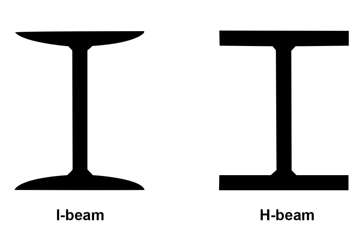
Have you ever wondered about the difference between H-beams and I-beams in construction? While they may look similar, these two types of steel beams have distinct characteristics that make them…
Are you tired of the rising costs of stainless steel for your projects? This article explores a cost-effective alternative to Stainless Steel 304—SUS443. Learn how SUS443 offers superior corrosion resistance,…
Have you ever wondered about the difference between Rockwell and Brinell hardness scales? In this article, we'll dive into the world of material hardness testing, exploring the key distinctions between…
Have you ever wondered what those numbers on sheet metal mean? In this article, we'll dive into the world of sheet metal gauge and demystify this essential aspect of metalworking.…
Have you ever wondered how the weight of a silver block is calculated? This article will unravel the mystery behind measuring silver using volume and density. By the end, you'll…
Have you ever wondered how to accurately calculate the weight of cast iron parts? In this insightful blog post, an experienced mechanical engineer shares their expertise on the density variations…
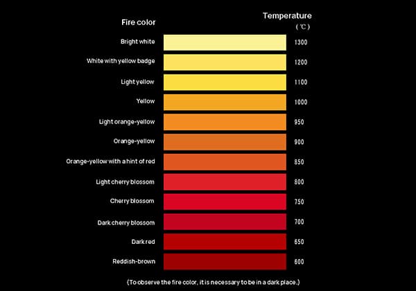
Have you ever marveled at the mesmerizing colors of heated steel? The vibrant reds, oranges, and yellows tell a fascinating story about temperature. In this article, we'll explore the science…
Have you ever wondered about the fascinating world of metal hardness? In this blog post, we'll dive into the intriguing concepts and methods behind measuring and enhancing the hardness of…