Offset Punch and Die: Methods and Adjustment Techniques
Ever wondered how precision in metalworking is achieved? The offset punch and die method is a key technique that allows for precise adjustments in offsets, essential for creating specific metal shapes. This article explains the components, patterns, and methods for using and adjusting these tools. By reading, you’ll gain a clear understanding of how to effectively utilize and fine-tune offset punch and die equipment for your metalworking projects.
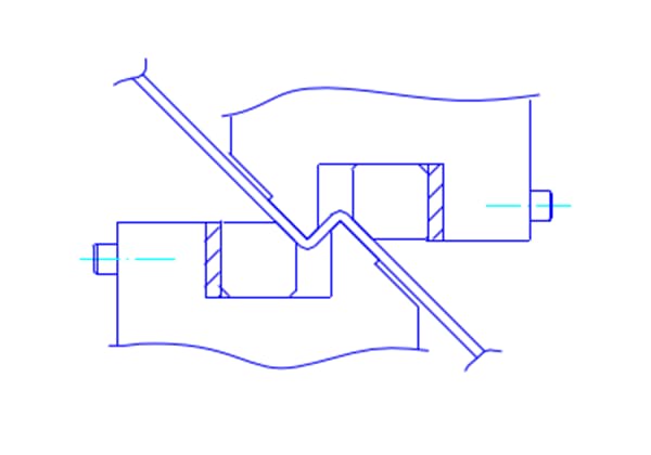
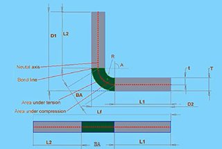
This product, shown in Figure below, consists of a mold body and a cushion, which can create increases and decreases in offsets, and perform segment folding by decreasing forward.
The cushion of the main component is fixed with bolts, and the thickness of the cushion can be changed, or the angles of the cushion can be changed, and the offset will change.
2. Patterns:
The maximum plate thickness applicable is SPCC-2.3t.
The range of offsets that can be produced is H=1~10MM.
2.1) The offset of the mold is determined by the assembly of the cushion and the angle of the component. For information on the offset of the mold, the assembly of the cushion, and the bevel amount of the component, refer to Table 1.
However, the offset of the product is equal to the offset of the mold. The exact amount of the offset of the mold for the product is confirmed through trial folding of each product, with both correct and erroneous results.
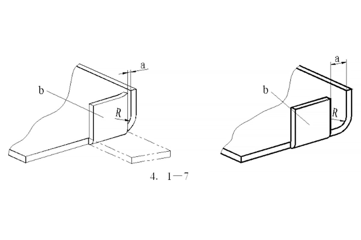
2.2) If the offset H is small, the angle θ will increase.
2.3) The bending radius R is generally less than or equal to R2. If the offset H is small, the R angle will also decrease.
2.4) The cushion is classified as a third class accessory, with 2 pieces each for 1.4t, 2.9t, and 4.9t, and combined with the bevel component.
3. Methods for Adjusting the Mold Using an Adjustment Pin
1)First, install the upper mold; after placing the lower mold on the lower mold installation seat, adjust it using the adjustment pin.
2)If the offset is relatively small (around H=1~2mm), the mold can also be calibrated directly by matching the upper and lower molds.
3)Adjustment method for the scale of the adjustment pin:
(1) When adjusting dimension A, the offset may vary due to differences in plate thickness or bending shape, and cannot be generalized. This is just a rough adjustment range: A = V/3 + 0.245t;
(2) Measure the vertical distance between points a and b, and the vertical distance between the two ends of the mold should be equal.
4)Precautions for Using the Adjustment Pin Tool:
4)-1 First, combine the bevel and shim according to the height of the offset and install the upper and lower molds, but do not fix the lower mold first.
4)-2 The adjustment of the adjustment pin fixture should be consistent with (0.245t) and the corresponding plate thickness. After adjusting to the corresponding scale, all screws should be tightened.
4)-3 As shown in the figure below, place two symmetrical adjustment pin fixtures on the lower mold, align them with the upper mold, and press down to about 1ton or less. After fixing the lower mold, remove the fixture.
4)-4 The dimension A shown in the above figure may change theoretically due to the offset and plate thickness. Because this fixture automatically sets the offset, only the plate thickness can be adjusted according to A = 0.245t. There are theoretical data and actual trial bending, and the best angle should be taken (especially for bending with different plate thickness or blunt angle bending, etc.).
Warning: Do not use more than the specified compression resistance of the mold;
If any damage to the mold is found, stop using it immediately.
The mold should be installed strictly according to the operating procedures.
As the founder of MachineMFG, I have dedicated over a decade of my career to the metalworking industry. My extensive experience has allowed me to become an expert in the fields of sheet metal fabrication, machining, mechanical engineering, and machine tools for metals. I am constantly thinking, reading, and writing about these subjects, constantly striving to stay at the forefront of my field. Let my knowledge and expertise be an asset to your business.
Imagine buying a press brake and realizing it doesn't meet your needs—an expensive mistake! This guide explains the critical principles and factors to consider when purchasing a press brake. From…
Have you ever wondered how a simple sheet of metal transforms into complex shapes? This blog post dives into the fascinating world of press brake machines and bending dies. Discover…
Have you ever struggled with sheet metal bending problems that left you scratching your head? In this insightful blog post, an experienced mechanical engineer shares their expertise on tackling common…
Are you struggling to design accurate sheet metal parts? Unlock the secrets of the K-factor, a crucial concept in sheet metal fabrication. In this article, our expert mechanical engineer demystifies…
Have you ever struggled with accurately unfolding sheet metal parts? This article explores the art and science behind sheet metal unfolding calculations. Discover the key concepts, formulas, and techniques used…
Have you ever wondered why sheet metal parts crack or deform during bending? This article explores the essential principles of sheet metal design, focusing on bending techniques to ensure precision…
Why do perfectly planned metal bends sometimes fail? Defects like cracks, warping, and twisting can plague bent parts, compromising their quality and functionality. This article dives into the causes behind…
Ever wondered why your sheet metal projects don’t always fit together perfectly? The key lies in understanding bend allowance. This concept ensures precise bending and reduces material waste. In this…
Have you ever wondered what makes press brake dies so fascinating? In this captivating blog post, we'll delve into the intricate world of these essential tools that shape the metal…