K Factor Calculator for Sheet Metal Bending (Online & FREE)
Are you struggling to design accurate sheet metal parts? Unlock the secrets of the K-factor, a crucial concept in sheet metal fabrication. In this article, our expert mechanical engineer demystifies the K-factor, explaining its relationship to the neutral layer and providing practical methods for calculation. Discover how mastering the K-factor can revolutionize your sheet metal designs and ensure successful manufacturing.
This article provides an in-depth exploration of the K-factor, a crucial concept in sheet metal design and fabrication. It covers the definition of the K-factor, its relationship to the neutral layer, and methods for calculating and calibrating the K-factor.
The article also discusses the factors influencing the K-factor, such as material properties and bending parameters, and provides practical guidance for determining the optimal K-factor value for various applications.
What Is the K-Factor?
The K-factor is a crucial concept in sheet metal design and fabrication, particularly when working with CAD software like SolidWorks. It represents the location of the neutral axis within a bend and plays a vital role in determining the accurate length of sheet metal parts after bending. Mathematically, the K-factor is defined as the ratio of the distance between the neutral layer and the inner surface of the bend (t) to the overall thickness of the sheet metal (T):
K = t / T
This dimensionless value always falls between 0 and 1, typically ranging from 0.3 to 0.5 for most common materials and bending processes. The K-factor is essential for several reasons:
Bend allowance calculation: It directly influences the amount of material consumed in a bend, affecting the flat pattern development and final part dimensions.
Material behavior prediction: Different materials and thicknesses exhibit varying neutral axis locations during bending, which the K-factor helps quantify.
Manufacturing precision: Accurate K-factor values ensure that bent parts meet design specifications, reducing scrap and rework in production.
Process optimization: Understanding K-factors for specific material-tooling combinations allows for more efficient bending operations and improved part quality.
Factors influencing the K-factor include material properties (such as yield strength and ductility), sheet thickness, bend radius, and bending method (air bending, bottoming, coining). Modern sheet metal fabrication often utilizes empirically derived K-factor tables or advanced finite element analysis (FEA) to determine optimal values for specific applications.
Understanding the Neutral Layer
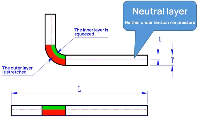
To fully grasp the K-factor, it’s essential to understand the concept of the neutral layer. When a sheet metal part is bent, the material near the inner surface of the bend undergoes compression, with the severity increasing closer to the surface. Conversely, the material near the outer surface experiences stretching, with the intensity increasing nearer to the surface.
Assuming the sheet metal is composed of thin stacked layers (as is the case with most metals), there must exist a layer in the middle that experiences neither compression nor stretching during bending. This layer is known as the neutral layer. The neutral layer is critical in determining the K-factor and, consequently, the bend allowance and flat pattern dimensions of a sheet metal part.
Relationship Between Neutral Layer, K-Factor, and Material Properties
The neutral layer, though invisible within the sheet metal, plays a pivotal role in bending operations and is intrinsically linked to the material’s properties. This relationship directly influences the K-factor, a critical parameter in sheet metal fabrication.
The position of the neutral layer is determined by several material characteristics:
Ductility: More ductile materials tend to have a neutral layer closer to the inner bend radius.
Yield strength: Higher yield strength materials typically exhibit a neutral layer position closer to the mid-thickness.
Work hardening rate: Materials with higher work hardening rates may show a shift in the neutral layer position during bending.
Anisotropy: The directional dependence of material properties can affect the neutral layer’s position in different orientations.
The K-factor, being a representation of the neutral layer’s position, is consequently influenced by these same material properties. It’s typically expressed as a decimal between 0 and 1, where 0.5 indicates the neutral layer at the sheet’s mid-thickness.
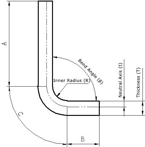
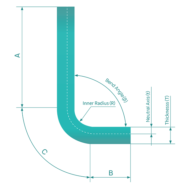
A fundamental principle derived from the neutral layer concept is that the unfolded (flat pattern) length of a bent sheet metal part equals the length of the neutral layer. This can be mathematically expressed as:
Unfolded length = straight length A + straight length B + arc length C
Where:
A and B are the straight sections of the part
C represents the neutral layer length in the bend region
This relationship is crucial for precise flat pattern dimensioning, which relies on accurate K-factor determination and bend allowance calculations. The bend allowance, in turn, is influenced by:
Material thickness
Bend radius
Bend angle
Material properties (especially elasticity and plasticity)
Understanding these interrelationships enables engineers to:
Optimize material utilization
Enhance bend accuracy
Minimize springback effects
Improve overall part quality and consistency
In practice, while theoretical calculations provide a starting point, empirical testing and adjustment of K-factors for specific material-tooling combinations often yield the most accurate results in production environments.
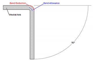
Understanding the K-Factor through Illustrations
The illustrations below provide a detailed visual explanation of the K-factor concept:
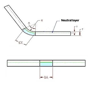
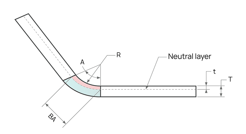
In the cross-section of a sheet metal part, there exists a neutral layer or axis. The material at this neutral layer within the bend region experiences neither compression nor stretching, making it the only area that remains undeformed during bending. In the diagram, the neutral layer is represented by the intersection of the pink (compression) and blue (stretching) regions.
A key insight is that if the neutral layer remains undeformed, the arc length of the neutral layer within the bend region must be equal in both the bent and flattened states of the sheet metal part. This principle forms the basis for calculating bend allowances and flat pattern dimensions using the K-factor.
Calculating Bend Allowance using the K-Factor
Therefore, the bending allowance (BA) should be equal to the length of the neutral layer arc in the bending area of the sheet metal part. This arc is represented as green in the Figure.
The position of the neutral layer in sheet metal depends on specific material properties, such as ductility.
Assuming the distance between the neutral sheet metal layer and the surface is “t,” that is, the depth from the surface of the sheet metal part to the sheet metal material in the thickness direction is t.
Therefore, the radius of the neutral sheet metal layer arc can be expressed as (R+t).
Using this expression and the bending angle, the length of the neutral layer arc (BA) can be expressed as:
To simplify the definition of the neutral layer in sheet metal and considering the applicability to all material thicknesses, the concept of the k-factor is introduced. Specifically, the k-factor is the ratio of the thickness of the neutral layer position to the overall thickness of the sheet metal part, that is:
Therefore, the value of K is always between 0 and 1. If a k-factor is 0.25, it means that the neutral layer is located 25% of the thickness of the sheet metal material, and if it is 0.5, it means that the neutral layer is located at the halfway point of the entire thickness, and so on.
Combining the above two equations, we can get the following equation:
Where some values such as A, R, and T are determined by the actual geometric shape.
K Factor Calculator
To accurately determine the K-factor value, we offer two precision calculators designed for different input scenarios. While the results may exhibit slight variations, both calculators provide reliable outcomes tailored to your specific metal forming requirements.
Calculator 1: Known Bend Allowance and Inside Bend Radius
This calculator is optimized for situations where you have precise measurements of the bend allowance and inside bend radius. It utilizes these parameters to compute the K-factor and the critical distance from the inside surface to the neutral axis (t), essential for accurate sheet metal bending calculations.
Inputs:
Material Thickness (T): The uniform thickness of the sheet metal workpiece, typically measured in millimeters or inches.
Inside Radius (R): The radius of the bend measured from the inside surface of the material, usually determined by the tooling used.
Bend Angle (A): The included angle of the bend, measured in degrees. This angle is crucial for determining the degree of material deformation.
Bend Allowance (BA): The length of the arc through the bend at the neutral axis, accounting for material stretching and compression during bending.
Outputs:
K-factor: A dimensionless value representing the location of the neutral axis within the material thickness. It’s crucial for accurate bend deduction calculations and compensating for material springback.
Neutral Axis Offset (t): The distance from the inside surface of the bend to the neutral axis, where neither compression nor tension occurs. This value is essential for precise bend allowance and developed length calculations.
Calculator 2: Known Inside Bend Radius and Material Thickness
If you only know the inside bend radius and material thickness, use this calculator to determine the K-factor.
Inputs:
Material Thickness (T)
Inside Radius (R)
Outputs:
K-factor
Neutral Axis Offset (t)
These calculators provide a convenient way to quickly determine the K-factor and neutral axis position for your sheet metal design projects.
K-Factor Calculation Formula and Example
Based on the previous calculations, we can derive the formula for calculating the K-factor:
Where:
BA is the bend allowance
R is the inside bend radius
K is the K-factor (t / T)
T is the material thickness
t is the distance from the inside surface to the neutral axis
A is the bend angle (in degrees)
Sample calculation:
Let’s work through a sample calculation using the following given information:
Sheet metal thickness (T) = 1 mm
Bend angle (A) = 90°
Inside bend radius (R) = 1 mm
Bend allowance (BA) = 2.1 mm
The formula to calculate the K factor is:
Step 1: Substitute the given values into the K-factor formula:
K = (2.1 × 180/(3.14 × 90) – 1)/1
Step 2: Simplify the equation:
K ≈ 0.337
Therefore, for the given parameters, the K-factor is approximately 0.337.
This example demonstrates how to apply the K-factor calculation formula to determine the K-factor for a specific sheet metal bending scenario.
K Factor Chart
The following are K-factors for common metal materials.
Soft copper or soft brass: K=0.35
Semi-hard copper or brass, mild steel, aluminium etc.: K=0.41
Bronze, hard bronze, cold rolled steel, spring steel, etc.: K=0.45
The following table provides bend allowance values obtained by a specific manufacturer for various materials and thicknesses. Please note that these values are for reference only and may not be universally applicable.
Material thickness (T)
SPCC
Al
SUS
Copper
0.8
1.4
1.4
1.5
–
1.0
1.7
1.65
1.8
–
1.2
1.9
1.8
2.0
–
1.5
2.5
2.4
2.6
–
2.0
3.5
3.2
3.6
37 (R3)
2.5
4.3
3.9
4.4
–
3.0
5.1
4.7
5.4
5.0 (R3)
3.5
6.0
5.4
6.0
4.0
7.0
6.2
7.2
6.9 (R3)
Note: For copper, the bend allowance values are coefficients when the inner bend radius is R3. When using an acute punch for bending, refer to the bend allowance for aluminum alloy or determine the value through trial bending.
Why the K-Factor Cannot Exceed 0.5
To understand why the K-factor cannot exceed 0.5, it’s crucial to comprehend the concepts of the K-factor and the neutral layer in sheet metal bending.
Understanding Sheet Metal Bending
Sheet metal bending involves creating a controlled deformation to form a small radius arc. Unlike roll forming, which produces larger radii, bending typically results in tighter curves. Regardless of the bending method employed (air bending, bottoming, or coining), achieving a perfect right angle is physically impossible due to material properties and tooling limitations. The workpiece radius is directly correlated to the lower die radius – a smaller die radius produces a tighter bend radius, and vice versa.
The Neutral Layer
In sheet metal bending, the material undergoes both compression on the inside of the bend and tension on the outside. This deformation creates a theoretical plane within the material thickness where neither compression nor tension occurs – this is known as the neutral layer or neutral axis.
When a sheet is bent, the inner surface dimensions decrease while the outer surface dimensions increase. This dimensional change gives rise to the bend allowance, a critical factor in precise bend calculations. For instance, when bending a 90-degree angle from a flat blank with outside dimensions of 20 x 20 mm, the unfolded length will always be less than 40 mm, regardless of material thickness. This is due to the elongation of the outer fibers during bending.
Shift of the Neutral Layer
Advanced research and high-precision manufacturing requirements have revealed that the neutral layer’s position is not always at the exact center of the material thickness. In fact, for small bend radii (typically when the inside bend radius is less than 2 times the material thickness), the neutral axis shifts towards the inside of the bend.
This shift occurs because the compressive forces on the inside of the bend are greater than the tensile forces on the outside, resulting in an asymmetrical strain distribution. For example, in a tight bend, the inside dimension might decrease by 0.3 mm, while the outside dimension increases by 1.7 mm, rather than equal 1 mm changes on both sides.
The K-Factor Defined
The K-factor is a dimensionless coefficient used to locate the position of the neutral layer within the material thickness during bending. It is defined as the ratio of the distance from the inside surface of the bend to the neutral layer, divided by the total material thickness.
Mathematically, K-factor = d / t, where: d = distance from inside bend surface to neutral layer t = total material thickness
Maximum K-Factor Value
The neutral layer’s position is constrained by the physical boundaries of the material. At its theoretical maximum, the neutral layer could be located at the exact center of the material thickness. In this case:
d (maximum) = t / 2 K-factor (maximum) = (t / 2) / t = 0.5
Therefore, the K-factor in sheet metal bending cannot exceed 0.5, as this would imply the neutral layer is positioned beyond the centerline of the material thickness, which is physically impossible.
In practice, K-factors typically range from 0.3 to 0.5, depending on material properties, bend radius, and forming process. Accurate determination of the K-factor is crucial for precise bend allowance calculations and achieving tight dimensional tolerances in sheet metal fabrication.
Variation Law of K Factor and Neutral Layer
1. Influence of Processing Technology
Even for the same material, the K-factor in actual processing is not constant and is affected by the processing technology. In the elastic deformation stage of sheet metal bending, the neutral axis is located at the middle of the plate thickness. However, as the bending deformation of the workpiece increases, the material undergoes mainly plastic deformation, which is unrecoverable.
At this point, the neutral layer shifts towards the inner side of the bend as the deformation state changes. The more severe the plastic deformation, the greater the inward offset of the neutral layer.
To reflect the intensity of plastic deformation during plate bending, we can use the parameter R/T, where R represents the inner bend radius and T represents the plate thickness. A smaller R/T ratio indicates a higher level of plate deformation and a greater inward shift of the neutral layer.
The table below shows data for plates with a rectangular cross-section under specific processing conditions. As R/T increases, the neutral layer position factor K also increases.
R/T
K
0.1
0.21
0.2
0.22
0.3
0.23
0.4
0.24
0.5
0.25
0.6
0.26
0.7
0.27
0.8
0.3
1
0.31
1.2
0.33
1.5
0.36
2
0.37
2.5
0.4
3
0.42
5
0.46
75
0.5
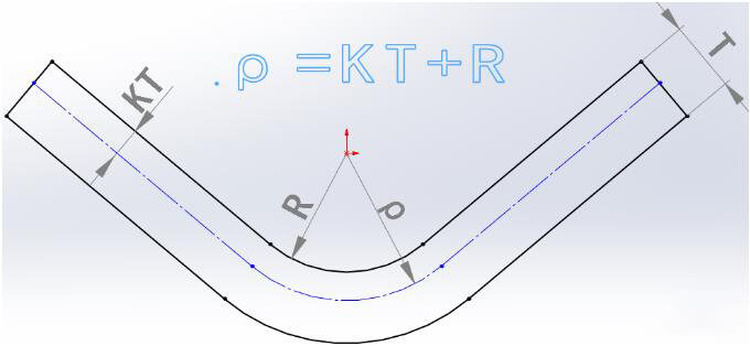
The radius of the neutral layer (ρ) can be calculated using the following formula:
ρ = R + KT
Where:
ρ – radius of the neutral layer
R – bend inner radius
K – neutral layer position factor
T – material thickness
Once the neutral layer radius is determined, its developed length can be calculated based on geometry, and subsequently, the sheet’s developed length can be derived.
2. Influence of Material Properties
Generally, under the same bending conditions, softer sheet metal materials have lower K values and larger inward offsets of the neutral layer.The Machinery’s Handbook provides three standard bending tables applicable to 90-degree bending, as shown below:
Table
Material
K Factor
# 1
Soft brass, copper
0.35
# 2
Hard brass, copper, mild steel, aluminum
0.41
# 3
Hard brass, bronze, cold rolled steel, spring steel
0.45
These tables demonstrate how material properties influence the K-factor and the neutral layer position.
3. Influence of Bend Angle on K-Factor
For bends with smaller inner radii, the bend angle can also affect the change in the K-factor. As the bend angle increases, the neutral layer experiences a greater offset towards the inner side of the bend. This relationship between bend angle and neutral layer shift is particularly significant for tight-radius bends and should be considered when determining the appropriate K-factor for a given sheet metal part.
Why Is K-Factor Calibration Necessary?
In sheet metal bending operations, calibrating the K-factor is crucial for achieving precise and consistent results. This calibration process is essential due to several factors inherent in metal forming:
Material Variability: Different sheet metal materials (e.g., steel, aluminum, copper) exhibit varying degrees of elasticity and plasticity, which directly impact the neutral axis location during bending. The K-factor, representing the position of this neutral axis, must be calibrated for each specific material to account for these differences.
Thickness Considerations: Sheet metal thickness significantly influences the bending behavior. As thickness increases, the relative position of the neutral axis shifts, necessitating K-factor adjustments. Calibration ensures accurate bend calculations across various material gauges.
Tooling Effects: The type and condition of bending tools (e.g., die width, punch radius) affect the material’s deformation characteristics. K-factor calibration accounts for these tooling variables, optimizing bend predictions for specific equipment setups.
Process Parameters: Bending forces, speeds, and techniques can vary between operations, influencing the final bend geometry. Calibrating the K-factor helps compensate for these process-specific factors, improving overall accuracy.
CAD Software Limitations: In SolidWorks and similar CAD platforms, bend deduction values for non-90-degree bends often require manual input, which can be time-consuming and error-prone. Utilizing a calibrated K-factor streamlines this process, allowing for more efficient and accurate modeling of complex sheet metal parts.
Manufacturing Precision: As modern sheet metal fabrication demands tighter tolerances, precise K-factor calibration becomes increasingly important. It ensures that the designed part closely matches the manufactured component, reducing assembly issues and rework.
Material Spring-back: Different materials exhibit varying degrees of spring-back after bending. A properly calibrated K-factor accounts for this elastic recovery, allowing for more accurate prediction of the final bend angle and overall part dimensions.
Cost Efficiency: Accurate K-factor calibration minimizes material waste and reduces the need for trial-and-error prototyping, leading to more cost-effective production processes.
By investing time in K-factor calibration, manufacturers can significantly improve the accuracy of their sheet metal bending calculations, enhance product quality, and optimize their design-to-manufacturing workflow. This calibration process, while initially requiring some effort, ultimately saves time and resources by reducing errors and iterations in the sheet metal fabrication process.
K-Factor Calibration Process
Here’s a comprehensive analysis of the K-factor calibration process for sheet metal design in SolidWorks:
Experimental Determination of Bend Deduction: Conduct practical experiments to determine accurate bend deduction values for various sheet metal thicknesses. This empirical approach ensures precision in subsequent modeling.
SolidWorks K-factor Calibration: a. Set the inner radius to 0.1mm for calibration purposes. This standardization is crucial as K-factor unfolding varies with different inner radii. b. Note: Maintain the 0.1mm inner radius setting during calibration. For actual part modeling post-calibration, adjust the inner radius as required for unfolding.
Calibration Procedure: a. Create a 10mm x 10mm sheet metal part in SolidWorks with the following parameters:
Material thickness: 1.5mm
Bend angle: 90 degrees
Inner radius: 0.1mm
Bend deduction: 2.5mm (experimentally determined) b. The resulting unfolded length should measure 17.5mm (10mm + 10mm – 2.5mm bend deduction).
K-factor Conversion: a. Initialize with an estimated K-factor (e.g., 0.3). b. Iteratively adjust the K-factor until the unfolded length precisely matches 17.5mm. c. In this example, a K-factor of 0.23 achieves the desired unfolded length.
Comprehensive Calibration: a. Repeat this calibration process for a range of sheet metal thicknesses relevant to your manufacturing processes. b. Document the calibrated K-factor values in a reference table, correlating them with specific material thicknesses and properties.
Advanced Considerations:
Material Properties: Consider the impact of material type (e.g., steel, aluminum, copper) on K-factor values.
Grain Direction: For anisotropic materials, calibrate K-factors for both with-grain and across-grain bending.
Temperature Effects: For applications involving extreme temperatures, consider calibrating K-factors at different temperature ranges.
Validation and Quality Control:
Periodically validate the calibrated K-factors through physical prototyping.
Implement a version control system for your K-factor reference table to track changes over time.
By meticulously following this calibration process, you ensure accurate sheet metal modeling in SolidWorks, leading to precise flat pattern development and optimized manufacturing processes.
Determining Optimal K-Factor Values Based on Material Properties
To determine the optimal K-factor value for sheet metal bending based on different material properties, it’s essential to understand the role and significance of the K-factor. The K-factor is a standalone value that describes how sheet metal bends and unfolds under various geometric parameters. It’s also used to calculate bend compensation for different material thicknesses, bend radii, and bend angles. Choosing the appropriate K-factor is crucial for ensuring accurate unfolding and bending of sheet metal parts.
The process of determining the optimal K-factor value based on material properties can be summarized in the following steps:
Understand Material Characteristics:
Comprehend the properties of the material being used, such as thickness, strength, and modulus of elasticity.
These characteristics directly influence the sheet metal’s behavior during bending and the required compensation.
Refer to Standard or Default Values:
Consult the sheet metal specification sheet for the default K-factor value based on the material.
This serves as a starting point, but keep in mind that each project may have specific requirements that deviate from the default values.
Perform Experimental Adjustments:
Set an initial K-factor value (e.g., 0.25) and conduct actual sheet metal unfolding and bending tests.
Observe whether the results match the expected outcomes.
If the unfolded dimensions differ from the expectations, return to the K-factor setting step and gradually adjust the value until achieving satisfactory precision.
Utilize Bend Deduction Tables:
In software like SolidWorks, specify bend deduction or bend allowance values for sheet metal parts using a bend deduction table.
Specify the K-factor value in its dedicated K-factor or bend allowance section.
This approach enables more precise control over the sheet metal bending process.
Consider Additional Bending Parameters:
Apart from the K-factor, take into account other factors such as bend radius, bend angle, and part thickness.
These parameters work together to determine the best practices for sheet metal bending.
By following these steps and considering the material properties, default values, experimental adjustments, bend deduction tables, and additional bending parameters, you can determine the optimal K-factor value for your specific sheet metal bending application.
FAQ
Q: What is the typical range of K-factor values for common materials?
A: The K-factor typically ranges from 0.3 to 0.5, depending on the material properties and forming conditions. For soft, ductile materials like annealed copper and aluminum, K-factors are generally lower, around 0.33 to 0.38. Medium-strength materials such as mild steel and brass typically have K-factors between 0.40 and 0.45. High-strength materials like stainless steel and spring steel tend to have higher K-factors, ranging from 0.45 to 0.50. It’s important to note that these values can vary based on factors such as sheet thickness, bend radius, and grain orientation.
Q: How do I choose the appropriate K-factor for my sheet metal design?
A: Selecting the appropriate K-factor involves considering multiple factors:
Material properties: Understand the mechanical characteristics of your chosen material, including yield strength, tensile strength, and ductility.
Sheet thickness: Thicker materials generally require higher K-factors due to increased strain distribution through the bend.
Bend radius: Smaller bend radii typically result in lower K-factors, while larger radii lead to higher values.
Bend angle: The severity of the bend angle can affect the K-factor, with more severe angles often requiring adjustment.
Grain direction: For anisotropic materials, consider whether the bend is parallel or perpendicular to the grain.
Forming process: The specific bending method (air bending, bottoming, coining) can influence the optimal K-factor.
Industry standards: Consult material-specific K-factor tables provided by industry organizations or material suppliers.
Empirical testing: For critical applications, conduct bending tests to determine the most accurate K-factor for your specific combination of material and forming conditions.
FEA simulation: Utilize finite element analysis software to predict material behavior and refine K-factor selection.
Experience and historical data: Leverage past projects and accumulated knowledge within your organization to inform K-factor choices.
Always validate your selected K-factor through prototyping or sample production before full-scale manufacturing to ensure accuracy and quality in the final parts.
Wrap It Up
In conclusion, the K-factor is a critical concept in sheet metal design and fabrication, serving as a key parameter for accurately predicting material behavior during bending operations. By understanding its relationship to the neutral axis position, material properties, and forming conditions, designers and engineers can create precise flat patterns and achieve optimal bend allowances.
Mastering the nuances of K-factor selection and application is essential for producing high-quality sheet metal parts with consistent dimensional accuracy and performance. As manufacturing technologies and materials continue to evolve, staying informed about the latest research and industry best practices regarding K-factor determination will remain crucial for maintaining competitive edge in sheet metal fabrication.
Further Reading and Resources
To deepen your understanding of sheet metal bending and related concepts, explore the following resources:
As the founder of MachineMFG, I have dedicated over a decade of my career to the metalworking industry. My extensive experience has allowed me to become an expert in the fields of sheet metal fabrication, machining, mechanical engineering, and machine tools for metals. I am constantly thinking, reading, and writing about these subjects, constantly striving to stay at the forefront of my field. Let my knowledge and expertise be an asset to your business.
Ever struggled to get perfect bends in sheet metal? This article dives into essential tips and tricks for mastering sheet metal bending, covering everything from process sequencing to analyzing bendability.…
Imagine turning raw materials into precise industrial components with just one step. This is the marvel of press brake die manufacturing. From mechanical extrusion to injection molding, the methods are…
How can you accurately bend a sheet metal part without trial and error? The Y-factor holds the key. This article explains the Y-factor, a crucial constant used to calculate the…
Have you ever wondered how sheet metal designers ensure the accuracy of their designs? In this blog post, we'll dive into the fascinating world of sheet metal design and explore…
Ever wondered why steel sometimes cracks during bending? In this article, we explore the fascinating world of steel bending technology, uncovering the reasons behind common defects like corner and central…
Imagine buying a press brake and realizing it doesn't meet your needs—an expensive mistake! This guide explains the critical principles and factors to consider when purchasing a press brake. From…
Have you ever wondered why some metal bends perfectly while others crack or warp? This article dives into the fascinating world of sheet metal bending, exploring the crucial factors that…
Ever wondered how to precisely unfold sheet metal for bending? Understanding the K-factor is key. This article breaks down the calculation process, providing engineers and technicians with a practical guide…
Have you ever struggled with calculating the right bend allowance for your sheet metal projects? In this blog post, we'll dive into the world of bend allowances and explore how…