Bend Allowance Formula: Calculator & Charts
Have you ever wondered how to precisely calculate the bending allowance for your metal fabrication projects? In this blog post, we'll explore the fascinating world of bend allowance formulas and…
Have you ever wondered how a simple sheet of metal transforms into complex shapes? This blog post dives into the fascinating world of press brake machines and bending dies. Discover the types of top punches and their unique applications, and learn how they make precise bends possible. Get ready to unlock the secrets behind metal bending!
Brief introduction:
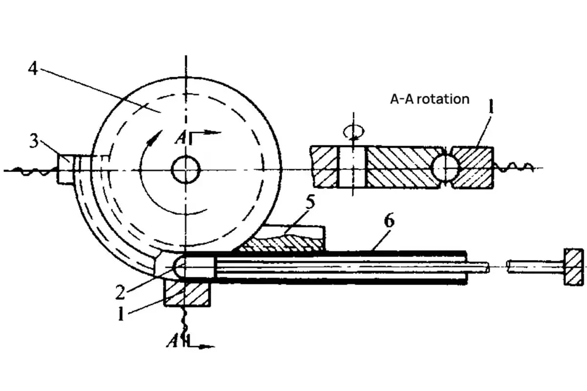
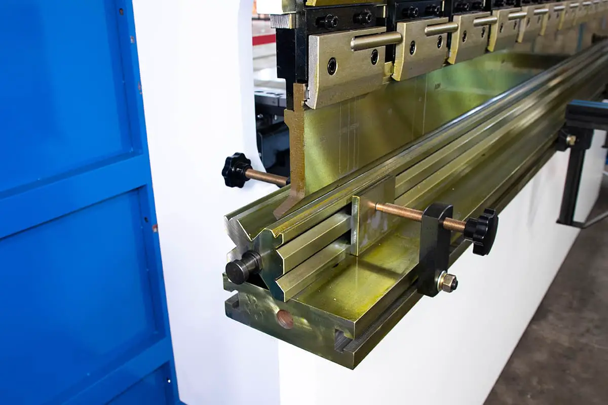
Bending is the process of bending a sheet by using a press brake machine and a bending die.
Bending dies, also known as press brake punches or blades, are divided into top punches and bottom dies.
The top punch is also called a folding blade.
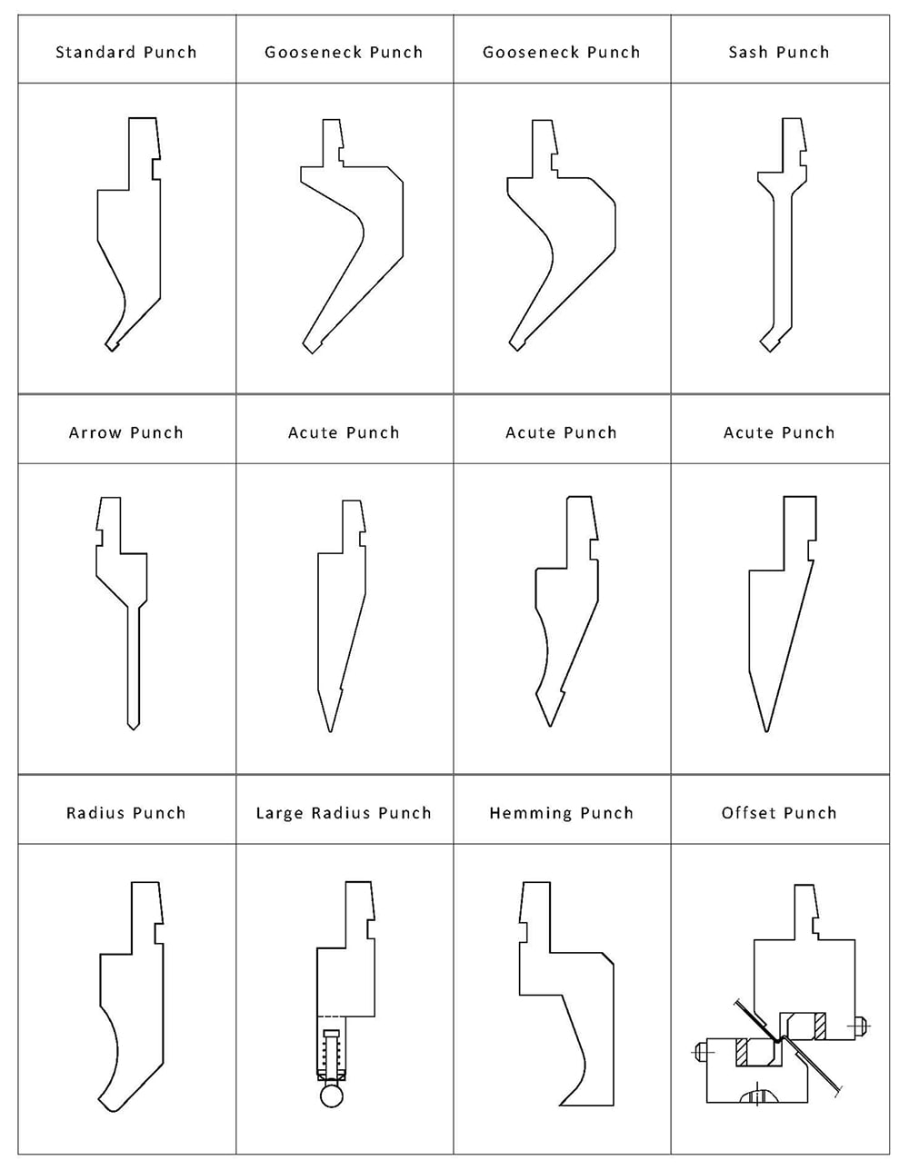
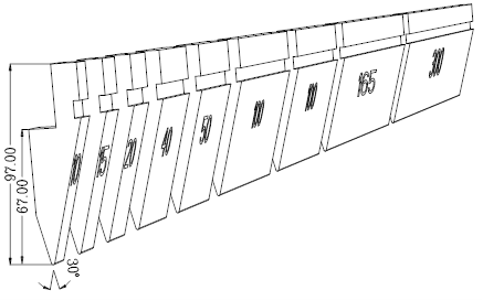
The specific classification of the upper and lower dies is shown in Figure 1.
A split length: 10,15,20,40,50,100 (right horn),100(left horn),200,300;
B split length: 10,15,20,40,50,100(right horn),100(left horn),165,300;
01) Standard Gooseneck Punch
| Pressure-tolerant Value(full length) | 20TON/M | Material | 42CrMo | Heat Treatment | HRC47±2 |
| Pressure-tolerant Value(separated) | 11TON/M | Tip Radius | 0.2R | ||
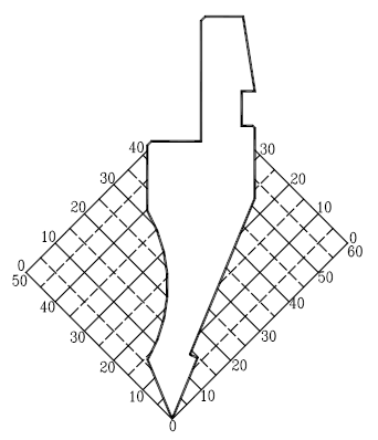
Coordinate graph(1:1):
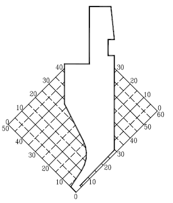
Processing characteristics:
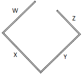
1. The application of the standard punch in the bending is mainly the avoidance of the W direction, and the bending diagram is as follows:

2. X direction: when Xmin>4mm, it can be bent (when the size is required in the W direction)
3. Y direction:when 0<Y<30mm, the Z direction cannot be avoided. When Y≧30mm, Z=Y-300
Split graph: B split

 Horn
Horn
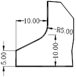
02) Gooseneck Punch
| Pressure-tolerant Value(full length) | 50TON/M | Material | 42CrMo | Heat Treatment | HRC47±2 |
| Pressure-tolerant Value(separated) | 45TON/M | Tip Radius | 0.2R | ||
Coordinate graph(1:2)

Processing characteristics:
1. The application of the gooseneck punch in the bending is mainly the avoidance of the W direction, and the bending diagram is as follows:

2. X direction: when Xmin>9mm, it can be bent (when the size is required in the W direction)
3. Y direction: when 0<Y<85mm, the Z direction cannot be avoided. When Y≧85mm, Z=Y-85
Split graph: A split

 Horn
Horn
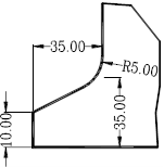
03) Gooseneck Punch
| Pressure-tolerant Value(full length) | 50TON/M | Material | 42CrMo | Heat Treatment | HRC47±2 |
| Pressure-tolerant Value(separated) | 30TON/M | Tip Radius | 0.2R | ||
Coordinate graph (0.8:1)
Processing characteristics:
1. The application of the gooseneck punch in the bending is mainly the avoidance of the W direction, and the bending diagram is as follows:

2. X direction: when Xmin>6mm, it can be bent (when the size is required in the W direction)
3. Y direction: When 0<Y<75mm, the Z direction cannot be avoided. When Y≧75mm, Z=Y-75
Split graph: A split

 Horn
Horn
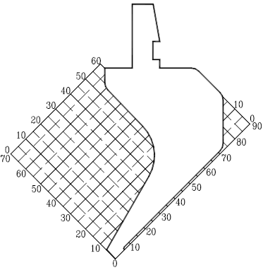
01) Sash Punch
| Pressure-tolerant Value(full length) | 30TON/M | Material | 42CrMo | Heat Treatment | HRC47±2 |
| Pressure-tolerant Value(separated) | 15TON/M | Tip Radius | 0.2R | ||
Coordinate graph(0.8:1)
Processing characteristics:
Suitable for bending symmetrical products. Both front and rear directions can be avoided.
When Xmin>10mm,W and X direction can increase in proportion.
When 0<Y<20mm,Z=0.
When Y>20mm, Y and Z directions can increase in proportion.
The bendable length in the W direction is greater than the bendable length in the Z direction.
Split graph: B split

 Horn
Horn
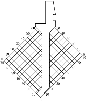
02) Arrow Punch
| Pressure-tolerant Value(full length) | 50TON/M | Material | 42CrMo | Heat Treatment | HRC47±2 |
| Pressure-tolerant Value(separated) | 12TON/M | Tip Radius | 0.2R | ||
Coordinate graph(0.8:1)
Processing characteristics:
1. Suitable for bending symmetrical products, both the front and rear directions can be avoided, and the bending opening can be as small as 6mm.
2. When X<50mm,Y<50mm,W and X direction can increase in proportion.
Split graph: A split
![]()
![]() Horn
Horn
03) Acute Punch
| Pressure-tolerant Value(full length) | 100TON/M | Material | AM87 | Heat Treatment | HRC47±2 |
| Pressure-tolerant Value(separated) | 20TON/M | Tip Radius | 0.65R | ||
Coordinate graph(0.8:1)

Processing characteristics:
1. Applicable range is between 30 ° and 180 °
2. Use a small angle of the tip of the tool to avoid the tapped hole and other workpieces that need to be avoided.

3. It is used for deep bending, and the insertion depth is suitable for bending angle as shown in the following figure:

Split graph: B split

 Horn
Horn
04) Acute Punch
| Pressure-tolerant Value(full length) | 60TON/M | Material | AM87 | Heat Treatment | HRC47±2 | |
| Pressure-tolerant Value(separated) | 30TON/M | Tip Radius | 0.37R | |||
Coordinate graph(1:1)
Processing characteristics:
1. Suitable for angles between 45° and 180°

2. Use a small angle of the tip of the tool to avoid the tapped hole and other workpieces that need to be avoided.

Split graph:A split

 Horn
Horn
05) Acute Punch
| Pressure-tolerant Value(full length) | 100TON/M | Material | AM87 | Heat Treatment | HRC47±2 |
| Pressure-tolerant Value(separated) | 30TON/M | Tip Radius | 0.52R | ||
Coordinate graph(1:1)

Processing characteristics:
1. Applicable range is between 30 ° and 180 °
2. Use a small angle of the tip of the tool to avoid the tapped hole

3. For deep bending, the depth of insertion is applicable to the bending angle as shown below

Split graph: B split
 Horn
Horn
01) Radius Punch
| Pressure-tolerant Value(full length) | 45TON/M | Material | 42CrMo | Heat Treatment | HRC47±2 |
| Pressure-tolerant Value(separated) | 45TON/M | Tip Radius | 1.5R,3.0R | ||
Coordinate graph(1:1)

Processing characteristics:
1. R radius is 1.5,3.0
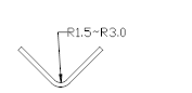
2. Radius punch is often used as bends for the upper cover
3. Sometimes used for shaping the workpiece with a small angle.
Split graph:A split


02) Large Radius Punch
| Pressure-tolerant Value(full length) | 45TON/M | Material | 42CrMo | Heat Treatment | HRC47±2 |
| Pressure-tolerant Value(separated) | 45TON/M | Tip Radius | 3.0R,4.0R5.0R,6.0R,8.0R,10.0R | ||
Graph (1:1)

Processing characteristics:
1. This large radius punch is mainly used for bending the inner arc angle of R, and the radius of the arc angle is R3~R10.
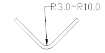
2. The radius punch is matched with the corresponding V groove
Combination graph:
01) Hemming Punch
| Pressure-tolerant Value(full length) | 100TON/M | Material | 42CrMo | Heat Treatment | HRC47±2 |
| Pressure-tolerant Value(separated) | Tip Radius |
Graph (1:1)
Processing characteristics:
1. The figure diagram shows the shape of the product after bending and flattening. All similar shapes can be bent. It should be used with 30° upper and lower molds.

2. Can also be used for pressing, riveting, shaping, etc.
Split graph:

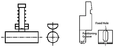
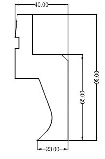
02) Offset Punch
| Pressure-tolerant Value(full length) | / | Material | 42CrMo | Heat Treatment | HRC47±2 |
| Pressure-tolerant Value(separated) | / | Tip Radius | / | ||
Graph (1:1)

Processing characteristics:
1. Used for Z bending which can’t be folded by common press brake dies.
H=1~10mm

2. The shape of the bend product is as shown in the upper right figure, usually called Z bend or offset.

As the founder of MachineMFG, I have dedicated over a decade of my career to the metalworking industry. My extensive experience has allowed me to become an expert in the fields of sheet metal fabrication, machining, mechanical engineering, and machine tools for metals. I am constantly thinking, reading, and writing about these subjects, constantly striving to stay at the forefront of my field. Let my knowledge and expertise be an asset to your business.