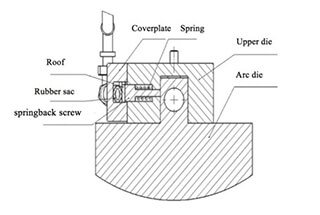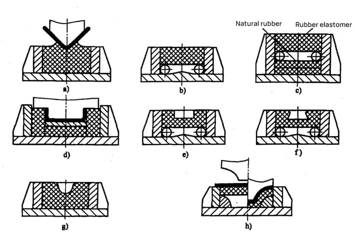
Essential Structural Designs for Common Bending Dies
Have you ever wondered how intricate the designs of bending dies can get? This article dives into the structural designs of common bending dies, from V-shaped to Z-shaped, explaining their…
Have you ever wondered why sheet metal parts crack or deform during bending? This article explores the essential principles of sheet metal design, focusing on bending techniques to ensure precision and durability. By the end, you’ll understand key strategies to prevent common issues in sheet metal fabrication.
Generally, sheet metal refers to metal materials with uniform thickness. Common sheet metal materials include stainless steel, galvanized steel, tinplate, copper, aluminum, and iron. This article primarily analyzes the basic principles of sheet metal product design.
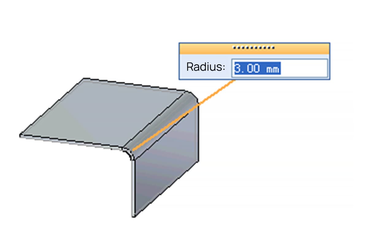
1. Minimum Bending Radius for Sheet Parts
When bending sheet parts, if the corner radius is too small, the outer surface is prone to cracking. If the corner radius is too large, the precision of the bent part is not easily maintained due to springback. Thus, a minimum bending radius is specified, as seen in Table below.
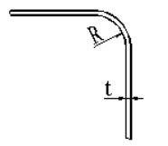
| Material | Minimum bending radius (R) |
| Cold rolled sheet, galvanized sheet, galvanized sheet | R ≥ 2t |
| Brass plate | R ≥ 1t |
| Aluminum alloy plate | R ≥ 1.2t |
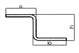
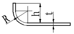
2. The height of the straight edge in bending should not be too small; otherwise, it is difficult to form sufficient bending moment to achieve parts with accurate shapes.
The value of h should be no less than R+2t, as shown in below.
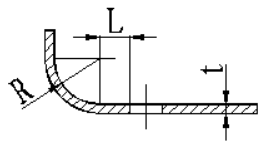
3. When punching near a bent edge, the distance L from the edge of the hole to the center of the bending radius R should not be too small to avoid deformation of the hole after bending.
The value of L should be no less than 2t, as presented in Figure below.
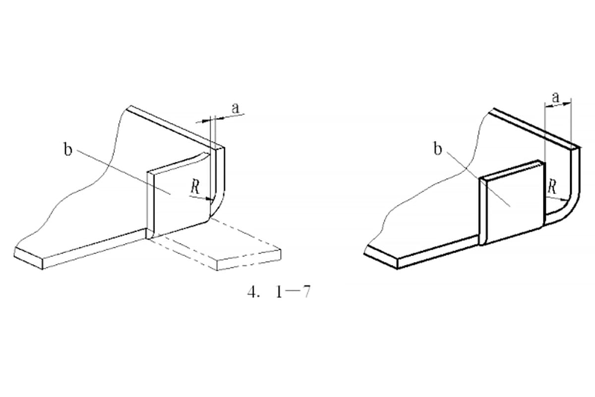
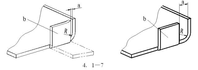
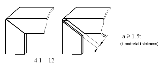
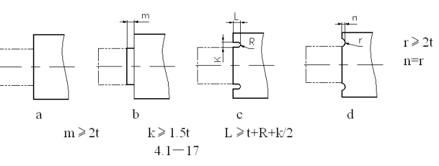
4. When a<R, a residual arc remains on side b near the point a after bending. To avoid this residual arc, ensure a≥R.
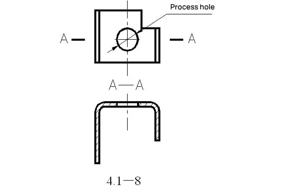
5. On U-shaped bent parts, it is best to have bend edges of equal length to prevent shifting to one side during bending.
Related reading: V & U-shaped Bend Force Calculator
If not permissible, a process locating hole can be set, as illustrated in Figure 4.1-8.
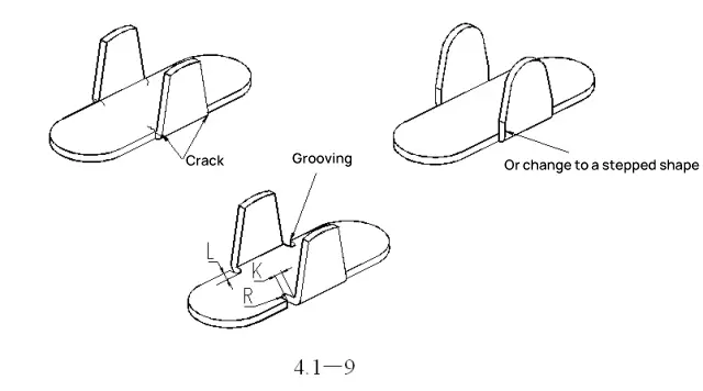
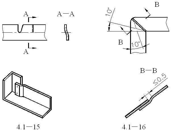
6. To prevent cracking or distortion during side (trapezoidal) bending.
Design a reserved slot or change the base to a step shape. The slot width K should be no less than 2t, and the slot depth L should be at least t+R+K/2.
7. To prevent wrinkling due to material compression at the corners during bending, design a reserved notch.
For example, the notch design at the corner of the outdoor unit side plate (top and bottom).
8. To prevent wrinkling on the flat sides of a right angle after bending, design a reserved notch.
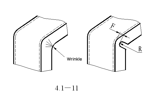
| R | F |
| 3 | 1.6 |
| 6 | 3 |
| 10 | 4.6 |
| 20 | 8 |
| 30 | 11 |
| 40 | 13 |
| 50 | 15 |
9. To prevent springback after bending, design a notch.
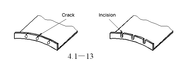
10. To prevent cracking after punching and subsequent bending, design a notch.
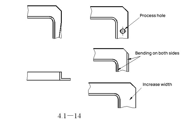
11. To prevent one side from shrinking inward during bending.
This can be resolved by designing a process locating hole, bending both sides simultaneously, or increasing the flange width to address shrinkage issues.
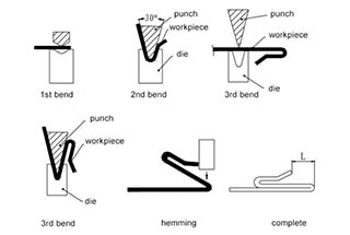
12. Overlapping form when bending into a right angle.
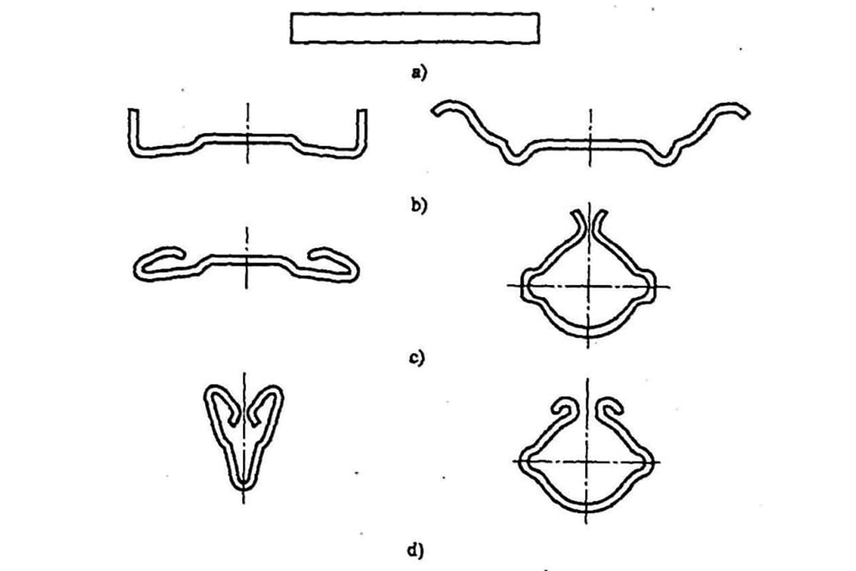
13. Bending of Protrusions
If bent like in Figure a, where the bending line coincides with the step line, cracking and deformation at the root can sometimes occur. Therefore, offset the bending line from the step line as in Figure b, or design a notch as shown in Figures c and d.
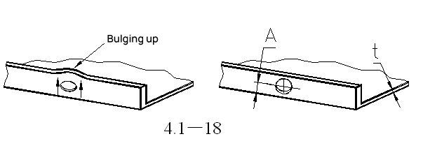
14. To prevent deformation of holes on the bending surface due to stress, the edge distance (to the bottom root) should be no less than A≥4.

As the founder of MachineMFG, I have dedicated over a decade of my career to the metalworking industry. My extensive experience has allowed me to become an expert in the fields of sheet metal fabrication, machining, mechanical engineering, and machine tools for metals. I am constantly thinking, reading, and writing about these subjects, constantly striving to stay at the forefront of my field. Let my knowledge and expertise be an asset to your business.