0° – 180° Bend Allowance Chart for Sheet Metal Bending
Have you ever wondered how sheet metal parts are designed and manufactured with precision? In this blog post, we'll dive into the fascinating world of bend allowance - a crucial…
Ever wondered why your sheet metal projects don’t always fit together perfectly? The key lies in understanding bend allowance. This concept ensures precise bending and reduces material waste. In this article, you’ll learn how to master bend allowance in SOLIDWORKS, making your designs accurate and efficient. Get ready to transform your sheet metal fabrication process!
Bend allowance is a critical parameter in sheet metal fabrication that helps determine the accurate flat length of the sheet material required to achieve the desired dimension after bending. It refers to the arc length of the bend as measured along the neutral axis of the material. The neutral axis is an imaginary line within the bend region where the material neither expands nor compresses during the bending process.
The calculation of bend allowance depends on various factors, such as the thickness of the sheet metal, the bend radius, and the bending angle. In SOLIDWORKS, users can define bend allowance values to gain precise control over the development of sheet metal parts.
Accounting for bend allowance is essential in producing accurately bent sheet metal parts. It ensures that the developed size of the part matches the design intent and guarantees that the bends will be made at the correct angles. This significantly reduces errors, material waste, and rework in the fabrication process.
Understanding and applying bend allowance values allows designers and fabricators to predict the behavior of the material during bending and avoid common sheet metal issues like over-bending or under-bending. Proper use of bend allowance in SOLIDWORKS enhances the efficiency of simulations and designing complex sheet metal parts.
The material properties play a significant role in determining the bend allowance in SolidWorks. Different materials have varying degrees of flexibility and resilience, affecting the bend allowance value. For instance, metals like aluminum, steel, and stainless steel have distinct elastic properties, leading to different bend allowance values for each material.
The bend angle is another crucial factor influencing the bend allowance. As the angle increases, the bend allowance generally increases as well. A larger bend angle requires more material to be deformed in the bending process, thus necessitating a larger bend allowance. In SolidWorks, the bend angle can be adjusted to generate the desired bend allowance value for the design.
The material thickness is directly related to the bend allowance, as thicker materials require more deformation and hence a larger allowance. A correct assessment of material thickness is essential in SolidWorks for accurate calculations and efficient sheet metal design. Thicker materials also demand higher forces for bending operations, resulting in increased requirements for equipment and tooling.
Bend Deduction, or BD, is a terminology used in sheet metal fabrication. It refers to the difference between the bend allowance and twice the outside setback in the material. This value is a key consideration when determining the overall flat length of sheet metal parts during the bending process. It helps fabricators create accurate sheet metal components that adhere to desired dimensions.
When working with SOLIDWORKS, designers have options to choose between using bend allowance and bend deduction values in their sheet metal designs. Both are useful for determining the final flat pattern of the sheet metal part and are essential for accurate manufacturing.
Bend allowance is the arc length of the bend as measured along the neutral axis of the material. It represents the length of the sheet metal being stretched or compressed during the bending process. The neutral axis refers to the region in the material where there is no stress or strain.
| Parameter | Description |
|---|---|
| Bend Allowance | Arc length of the bend along the neutral axis of the material |
| Bend Deduction | Difference between the bend allowance and twice the outside setback |
| BD | Bend Deduction abbreviation |
When using SOLIDWORKS, it is essential to input the correct bend allowance value or bend deduction value, depending on the selected method. This ensures that the final sheet metal part will have the desired dimensions and fit properly in assemblies.
Both methods have their benefits and considerations. Bend allowance calculations give a more accurate representation of the bending process and consider material behavior during bending. Bend deduction simplifies the calculation process and is easier to understand for those new to sheet metal design.
In conclusion, understanding the differences between bend allowance and bend deduction is crucial for accurate sheet metal design within SOLIDWORKS. Accurate input of these values ensures that the final sheet metal component adheres to design specifications and fits seamlessly in the desired assembly.
You can directly use our bend allowance calculator to calculate the bending allowance. Besides, the fabrication calculator can also help you calculate K-factor, Y-factor, bend allowance, bend deduction, etc.
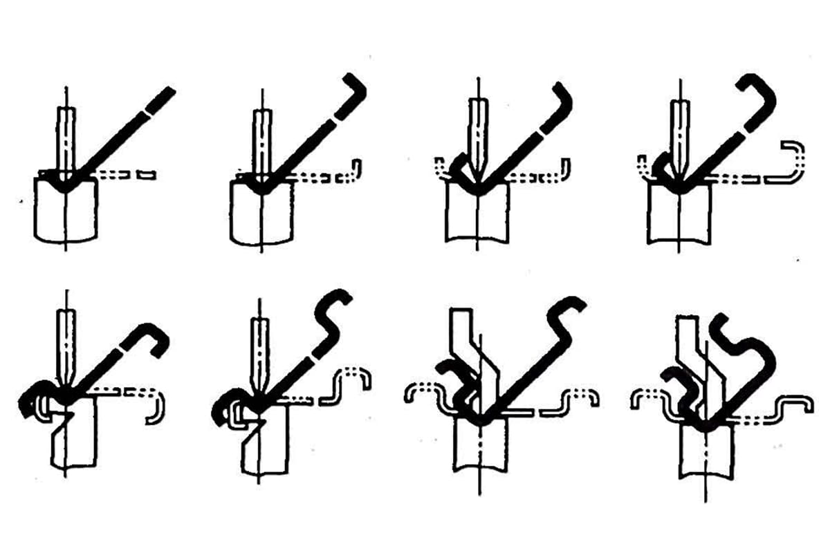
You may be wondering what exactly bend allowance is if you’ve never worked with sheet metal before.
When a sheet is bent in a press brake, the part of the sheet close to and in contact with the punch elongates to compensate for the given bend.
If you compare the length of this part before and after the bending, you’ll find that they’re different.
As an engineer, if you don’t compensate for this variation, the final product won’t have accurate dimensions.
This is more critical for parts where you have to maintain a tighter allowance or precision.
In this post, I cover some of the basic problems and principles you have to deal with regularly when working with sheet metal.
Before we get started, I want to comment on something – there is not really a scientific method or formula for determining the exact calculation of the bend allowance, because there are so many factors at play during the production of your sheet metal part.
For example, actual material thickness, an infinite variety of tooling conditions, forming methods, and so on.
There are many variables here, and in reality, many methods are used to calculate the bend allowance.
Trial and error is probably the most popular method, while bend tables are another commonly used technique.
Bend tables are typically available from metal suppliers, manufacturers, and engineering textbooks. Some companies develop their own bending tables based on their standard formulas.
Now, let’s return to Solidworks. How does Solidworks calculate bend allowance exactly? Solidworks uses two methods: bend allowance and bend deduction.
I’m going to explain what these methods are and show you how they are used in Solidworks.
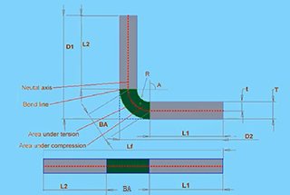
The bend allowance method is based on the formula that appears in my diagram.
The total length of the flattened sheet is equal to the sum of L1 (the first length), L2, and the bend allowance.
The bend allowance region is shown in green on my diagram. This is the region where all deformation occurs during the bending process.
Generally, the bend allowance will be different for each combination of material type, material thickness, bend radius, bend angle, and different machining processes, types, speeds, and so on. The list of potential variables is extensive.
The value of the bend allowance from sheet metal suppliers, manufacturers, and engineering textbooks is provided in bend tables. A bend table looks like the following Excel spreadsheet.
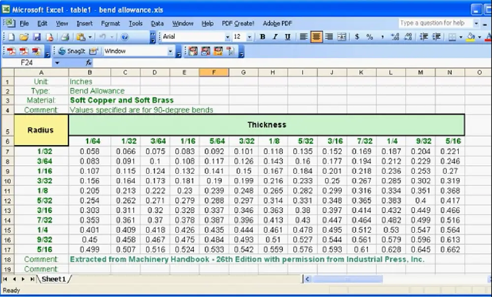
The bend table approach is probably the most accurate method for calculating bend allowance.
You can input your data manually into a matrix of the bend angle and bend radius. If you are not sure of the bend allowance value, you can run some tests.
You need a piece of the exact same sheet metal you will use to manufacture your part, and then you bend it using the same processes you will use during your machining. Simply take some measurements before and after bending, and based on the same information, you can adjust the necessary bend allowance.
Another method that Solidworks uses is the bend deduction method.
The formula is as follows:
The flattened length of the parts, Lf, equals D1 plus D2 minus the bend deduction.
Like bend allowance, bend deduction comes from the same sources: tables and manual testing.
As you can see, it is easy to understand how these values are related to each other based on the information provided by these formulas.
Another method for calculating bend allowance uses the K-factor.
K represents the neutral axis offset.
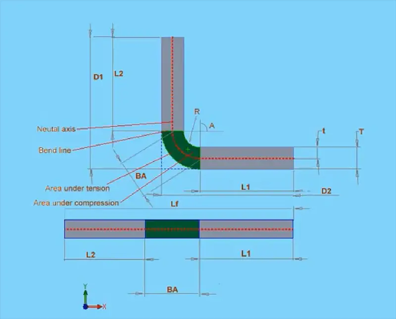
The general principle of this formula is as follows: the neutral axis (shown in red in my diagram) does not change during the bending process. During the bending process, the material inside the neutral axis will compress, and the material outside the neutral axis will stretch. The neutral axis will be closer to the inside bend (indicated in blue in the diagram). The more the part bends, the closer the neutral axis will be to the inside of the part.
The bend allowance calculation formula with the K-factor is shown below:
BA = 2πA(R+KT)/360
The K-factor equals t, which is the offset distance to the neutral axis, divided by big T, which is the thickness of the material.
In this formula, the bend allowance equals 2 times pi multiplied by A (the angle) multiplied by the sum of R (the bend radius) and the K-factor multiplied by T (the thickness of the material). Then, you divide all of this by 360.
In theory, the K-factor can be anywhere between 0 and 1, but for practical purposes, it is typically between 0.25 and 0.5.
For example, hard materials like steel have a higher K-factor, such as 0.5, while soft materials like copper or brass will have a lower K-factor closer to 0.
And don’t worry, this is the last formula we will be walking through in this lesson. It might seem a little confusing now, but with some practice, it will become second nature.
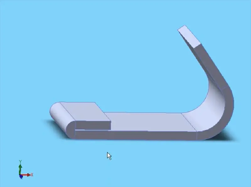
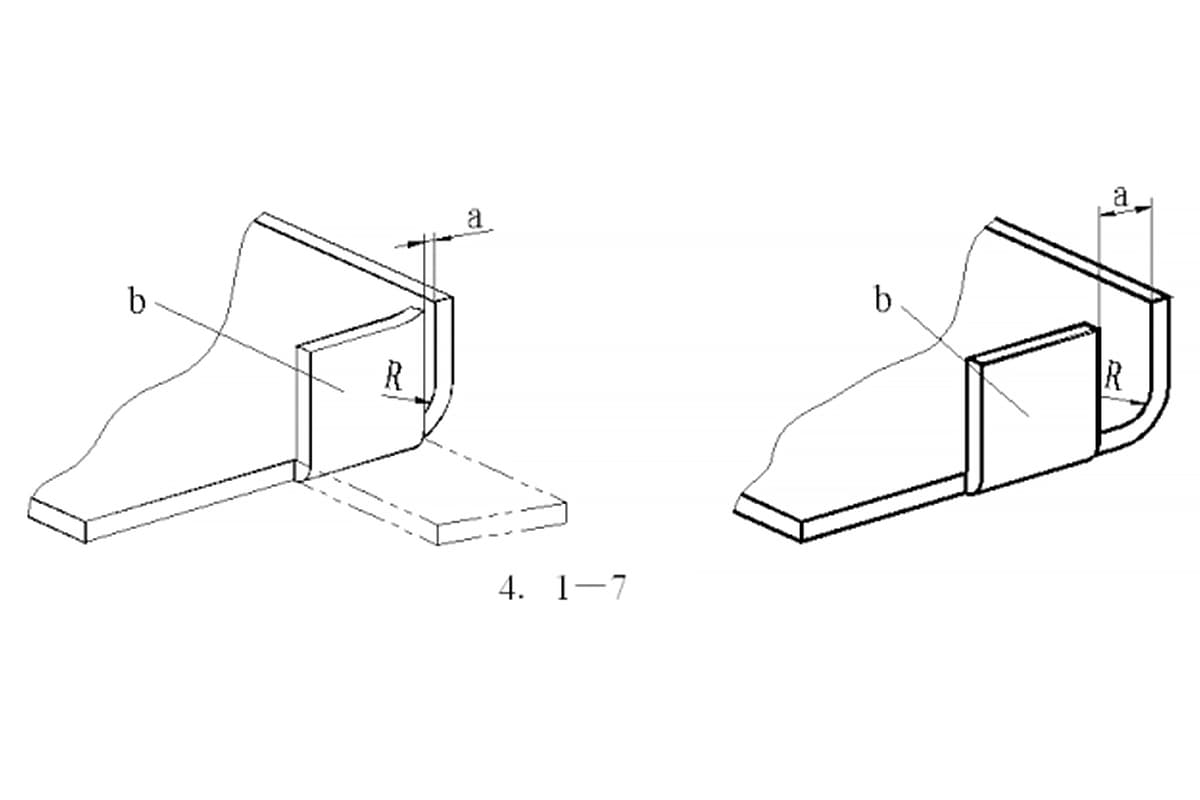
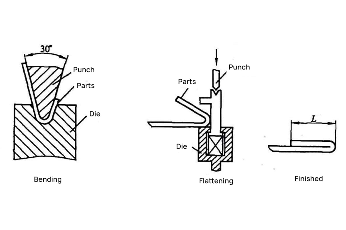
One last point: let’s take a look at the example. There is a hem on this part that has a K-factor of around 0.3. On the other hand, a soft bend, such as the gradual bend on the other side of this part, has a higher K-factor of about 0.5. And this concludes our lesson on bend allowance.
Further reading:

As the founder of MachineMFG, I have dedicated over a decade of my career to the metalworking industry. My extensive experience has allowed me to become an expert in the fields of sheet metal fabrication, machining, mechanical engineering, and machine tools for metals. I am constantly thinking, reading, and writing about these subjects, constantly striving to stay at the forefront of my field. Let my knowledge and expertise be an asset to your business.