Have you ever struggled with sheet metal bending problems that left you scratching your head? In this insightful blog post, an experienced mechanical engineer shares their expertise on tackling common challenges in the metal bending process. From preventing bend cracking to ensuring precise hole positioning, you’ll discover practical solutions and valuable tips to optimize your sheet metal bending techniques and achieve flawless results every time.
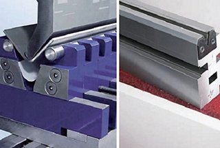
Metal sheets are bent and formed using a plate bending machine, also known as a press brake. The workpiece is placed on the machine, and the lifting lever is used to lift the brake block, allowing the workpiece to be positioned accurately. Once the workpiece is in place, the brake block is lowered onto it, and the bending lever is pressed to bend the metal sheet to the desired angle.
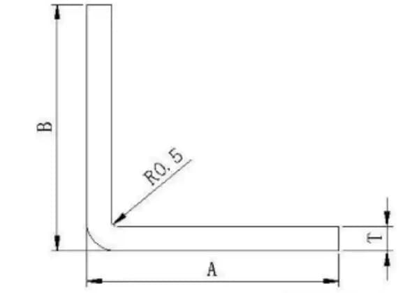
Determining the Minimum Bending Radius
The minimum bending radius is a critical factor in the bending process, determined by the ductility and thickness of the metal being formed. For aluminum sheet metal, the bending radius should be greater than the thickness of the plate. This ensures that the metal does not crack or break during the bending process.
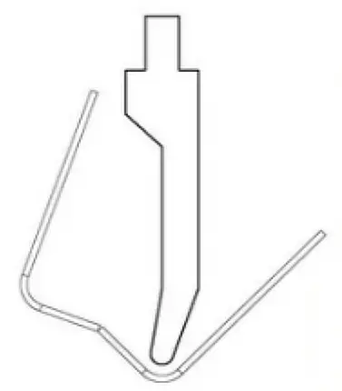
Figure 1 Normal bending
Elasticity and Bending Angle
Due to the material’s elasticity, the bending angle of the metal is often slightly greater than the required angle. This phenomenon, known as springback, must be accounted for during the bending process to achieve the precise angle needed.
Metal Sheet Processing Techniques
Bending is just one of the many techniques used in metal sheet processing, typically carried out in a metal processing workshop. Other techniques include:
Riveting: Joining metal sheets using rivets.
Welding: Fusing metal sheets together using heat.
Common Problems and Solutions in Metal Bending
During the bending process, several common issues may arise, including:
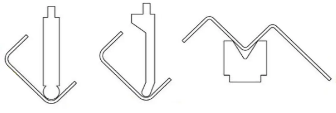
1. Challenges in Bending Groove-Type and Multi-Bend Workpieces
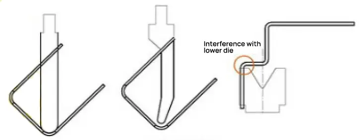
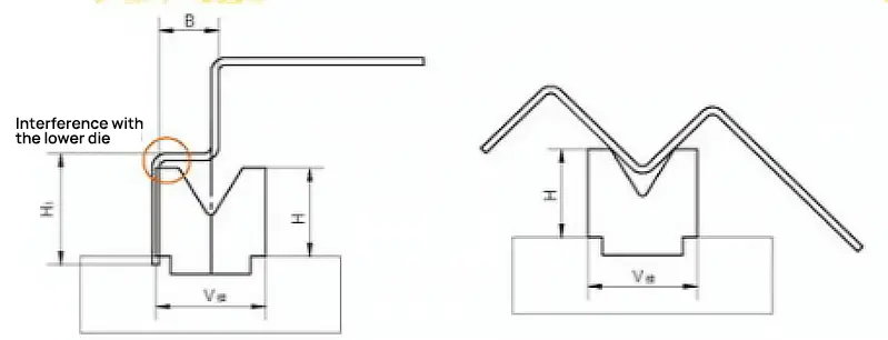
During the bending process of these workpieces, the groove width is larger than the leg height, leading to interference between one end of the workpiece and the upper die or the slider on the press brake. This makes it impossible to guarantee the dimensions of the workpiece, as shown in Figure 2.
Figure 2: Interference Detail Diagram
Predicting Interference in Sheet Metal Bending
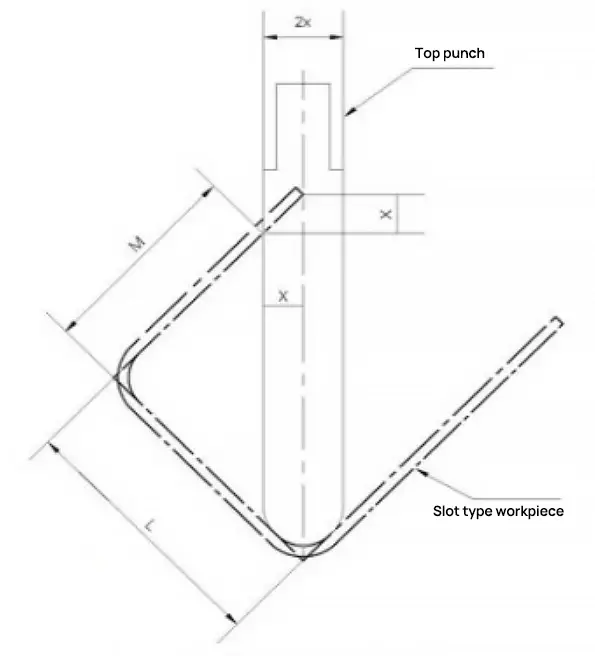
When dealing with high-leg precision sheet metal parts, determining whether bending can be completed requires multiple calculations, with corresponding dimensions indicated in Figure 3.
Figure 3: Relevant Dimensions of Groove-type Workpieces Bending
If L-M<1.5x, the workpiece can be bent without interference. If L-M>1.5x, the workpiece cannot be bent as it would cause interference.
Solutions to Interference Problems
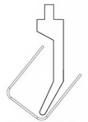
(1) If a groove-type workpiece experiences bending interference, a goose-neck upper die can be selected for bending. This avoids interference between the bending edge of the workpiece and the press brake or upper die, ensuring the bending dimensions of the workpiece, as shown in Figure 4.
Figure 4: Bending Using a Gooseneck Top Die
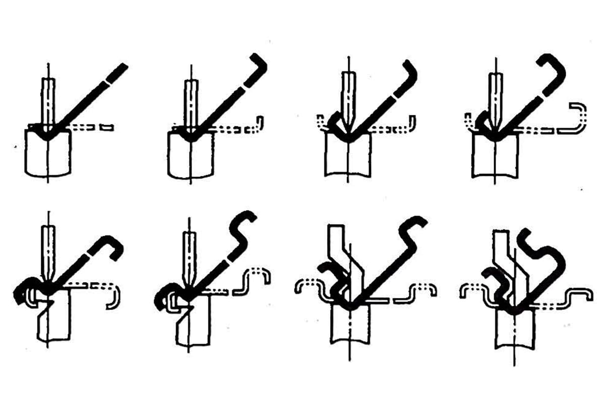
(2) If a groove-type workpiece experiences bending interference and there are no suitable goose-neck upper dies available, a reverse pre-bend can be performed in the middle of the bend without affecting usage requirements, as shown in Figure 5. By artificially increasing the bending angle, the workpiece can be bent normally. Then, a flat tire die can be used to spot press the pre-bend area to ensure product quality requirements are met.
Figure 5: Pre-bending
(3) When bending multi-bend workpieces, if H1>H or B<V/2, interference can occur between the workpiece and the lower die opening and workbench. The choice of lower die and bending sequence becomes very important, and the following methods can be used:
① Select a high-dimension lower die with H>H1 to ensure normal bending of the workpiece; ② Select a lower die opening with B>V/2 to ensure normal bending of the workpiece; ③ If there is no high-dimension lower die, change the bending sequence. Pre-deform the middle bend to a certain angle, then bend at the short side, form the third bend, and finally repress the middle bend to the required size and angle, ensuring the workpiece’s process size, as shown in Figure 6.
Figure 6: Multi-pass Bending
2. Bend Cracking
Analysis of Causes:
Bend cracking is a common issue that occurs on the tensile surface of sheet metal parts during the bending process. This phenomenon can significantly damage the mechanical properties of the workpiece, rendering it unusable and leading to economic losses due to scrapping. The primary causes of bend cracking include:
Crystal Structure and Rolling Grain Direction: Sheet metal has a specific crystal structure and rolling grain direction. Bending parallel to the grain direction increases the likelihood of fractures due to the alignment of the grains, which can create weak points.
Small Bending Radius (R): Selecting a bending radius that is too small can cause excessive stress on the material, leading to cracks.
Lower Die’s V-Groove R Angle: A small R angle in the lower die’s V-shaped groove can concentrate stress on the material, increasing the risk of cracking.
Material Performance: Poor material performance, such as low ductility or toughness, can make the sheet metal more susceptible to cracking during bending.
Preventive Measures:
To prevent bend cracking, several strategies can be implemented:
Cutting Orientation: When cutting the sheet metal, rotate it so that the cutting direction is perpendicular to the bending direction. This means the material’s bending direction should be perpendicular to the grain, reducing the risk of fractures.
Increase Upper Die R Angle: Using an upper die with a larger R angle can distribute the stress more evenly across the material, reducing the likelihood of cracking.
Use a Lower Die with a Large R Angle: Selecting a lower die with a larger R angle for processing can help in minimizing stress concentration on the material, thereby preventing cracks.
Choose High-Performance Materials: Opting for materials with better mechanical properties, such as higher ductility and toughness, can significantly reduce the risk of bend cracking.
3. The Bending Edge is Not Straight and the Size is Unstable
Cause Analysis:
No Line Pressing or Pre-bending
Explanation: Line pressing or pre-bending techniques are essential to ensure that the material is properly aligned and pre-stressed before the final bending operation. Without these techniques, the material may not bend uniformly, leading to an uneven edge and unstable dimensions.
Inadequate Material Pressure
Explanation: Insufficient pressure applied to the material during the bending process can result in incomplete or uneven bending. This can cause the material to spring back or bend inconsistently, leading to a non-straight edge and size instability.
Dissymmetric Convex-Concave Die Fillet and Uneven Bending Pressure
Explanation: If the convex-concave die fillet is not symmetrical or if the bending pressure is unevenly distributed, it can cause irregularities in the bending process. This can lead to variations in the bend angle and radius, resulting in an unstable size and non-straight edge.
Low Height
Explanation: If the height of the bend is too low, it may not provide sufficient leverage for a clean and consistent bend. This can cause the material to deform unevenly, leading to a non-straight edge and size instability.
Solutions:
Design Line Pressing or Pre-bending Techniques
Implementation: Incorporate line pressing or pre-bending steps into the bending process. These techniques help to pre-stress the material and ensure that it is properly aligned before the final bend. This can be achieved through the use of specialized tooling or additional processing steps.
Increase Jacking Force
Implementation: Ensure that the material pressure is adequate by increasing the jacking force. This can be done by adjusting the machine settings to apply more pressure during the bending process. Adequate pressure helps to achieve a more uniform bend and reduces the likelihood of spring-back.
Ensure Even Clearance in the Convex-Concave Die and Polish Fillet
Implementation: Check and adjust the clearance in the convex-concave die to ensure it is even. Additionally, polish the fillet to remove any irregularities. This helps to distribute the bending pressure more evenly and reduces the risk of irregular bends.
Make the Height Larger or Equal to the Minimum Size
Implementation: Ensure that the height of the bend is at least equal to the minimum required size. This provides sufficient leverage for a clean and consistent bend. Adjust the design or tooling as necessary to achieve the appropriate height.
4. Workpiece Scraping After Bending
Cause Analysis:
Unsmooth Material Surface
An uneven or rough surface on the material can lead to scraping during the bending process. This is because the irregularities on the surface can cause friction and resistance, resulting in damage to the workpiece.
Too Small Convex Die Bending Radius
If the bending radius of the convex die is too small, it can lead to excessive stress concentration on the material. This can cause the material to scrape or even crack during the bending process.
Too Small Bending Clearance
Insufficient clearance between the die and the punch can result in excessive pressure on the material. This can cause the material to scrape against the die, leading to surface damage.
Solutions:
Improve the Smoothness of the Concave Die
Ensuring that the concave die has a smooth surface can reduce friction and prevent the material from scraping. This can be achieved through polishing or using a die with a higher surface finish.
Increase Convex Die Bending Radius
Increasing the bending radius of the convex die can distribute the stress more evenly across the material, reducing the likelihood of scraping. This adjustment can help in maintaining the integrity of the workpiece during bending.
Adjust Bending Clearance
Properly adjusting the clearance between the die and the punch is crucial. Ensuring that there is adequate clearance can prevent excessive pressure on the material, thereby reducing the risk of scraping. This can be done by recalibrating the bending machine or using dies with appropriate dimensions.
5. Cracks at Bending Angles
Cause Analysis:
Too Small Bending Radius:
When the bending radius is too small, the material undergoes excessive stress, leading to cracks at the bending angles.
Material Grain Parallel to the Bending Line:
The orientation of the material grain significantly affects its bending properties. If the grain direction is parallel to the bending line, it can cause cracks due to the material’s anisotropic nature.
Burr of Workblank Extending Outward:
Burrs on the edges of the workpiece can act as stress concentrators, leading to cracks during bending.
Poor Remoldability of Metal:
Metals with low ductility or poor remoldability are more prone to cracking during bending operations.
Solutions:
Increase the Bending Radius of the Convex Die:
By increasing the bending radius, the stress concentration at the bending point is reduced, thereby minimizing the risk of cracks.
Change Blanking Layout:
Adjusting the blanking layout to ensure the material grain direction is perpendicular to the bending line can improve the material’s ability to withstand bending stresses.
Making Burrs at the Workpiece’s Inner Fillet:
Ensuring that burrs are directed towards the inner fillet of the workpiece can help in reducing stress concentration on the outer surface, thereby preventing cracks.
Annealing or Using Soft Material:
Annealing the material can improve its ductility and reduce the likelihood of cracking. Alternatively, using a softer material with better remoldability can also mitigate the issue.
6. Bending Causes Hole Deformation
Cause Analysis:
When elastic bending is used for positioning a hole, the outer surface of the bending arm is subjected to friction from both the surface of the concave mold and the outer surface of the workpiece. This frictional force can lead to deformation of the positioning hole. The deformation occurs because the material around the hole is not uniformly supported and is pulled unevenly during the bending process.
Solutions:
To mitigate hole deformation during the bending process, consider the following solutions:
Employ Shape Bending: Shape bending involves using specialized tooling that conforms more closely to the final shape of the workpiece. This method helps distribute the bending forces more evenly, reducing the likelihood of hole deformation.
Increase Coverboard Pressure: By increasing the pressure applied by the coverboard, the workpiece is held more securely in place. This added pressure helps to minimize movement and slippage, thereby reducing the deformation of the hole.
Add Pitting Plaid to Coverboard: Introducing a pitting plaid (a textured surface) to the coverboard increases friction between the workpiece and the coverboard. This increased friction helps prevent the workpiece from sliding during bending, which in turn reduces the chances of hole deformation.
7. Thinner Bending Surface
Cause Analysis:
Too Small Convex-Concave Die Fillet Radius:
When the fillet radius of the convex-concave die is too small, it can lead to excessive thinning of the material at the bending surface. This is because a smaller radius concentrates stress on a smaller area, causing more significant deformation and thinning.
Too Small Convex-Concave Die Clearance:
Insufficient clearance between the convex and concave dies can also contribute to a thinner bending surface. This limited space can cause the material to be excessively compressed and stretched, leading to thinning.
Solutions:
Increase the Radius of Convex-Concave Die Fillet:
By increasing the fillet radius of the convex-concave die, the stress distribution during bending becomes more uniform. This reduces the concentration of stress and minimizes material thinning. A larger radius allows the material to flow more smoothly around the bend, preserving its thickness.
Adjust the Convex-Concave Die Clearance:
Properly adjusting the clearance between the convex and concave dies ensures that the material is not excessively compressed or stretched. Adequate clearance allows the material to bend without significant thinning, maintaining the integrity of the bending surface.
8. Workpiece Surface Bulging or Unevenness
Cause Analysis:
During the bending process, the workpiece surface may become bulging or uneven due to the differential stresses experienced by the material. Specifically, under the tension in the circumferential direction, the outer surface of the material shrinks while the inner surface extends. This differential deformation can lead to bulging in the bending direction.
Solutions:
To address the issue of surface bulging or unevenness, consider the following solutions:
Provide Adequate Pressure to Convex-Concave Die at the Final Stamping Stage
Ensuring that adequate pressure is applied to the convex-concave die during the final stamping stage can help in achieving a more uniform deformation. This pressure helps in minimizing the differential stresses between the inner and outer surfaces of the workpiece.
Make Concave Round Angle Radius Equal to That of the Workpiece’s Excircle
By matching the concave round angle radius to the radius of the workpiece’s excircle, the bending process can be optimized to reduce stress concentration points. This alignment helps in distributing the stresses more evenly across the material, thereby reducing the likelihood of bulging.
Optimize Techniques
Material Selection: Choose materials with better ductility and uniformity to reduce the risk of uneven deformation.
Tooling Design: Ensure that the tooling is designed to accommodate the specific material and bending requirements. Properly designed tooling can help in achieving more consistent results.
Process Parameters: Adjust process parameters such as bending speed, pressure, and temperature to optimize the bending process. Fine-tuning these parameters can help in minimizing differential stresses and achieving a smoother surface.
9. Uneven Concave Part at the Bottom
Cause Analysis:
Uneven Material: The raw material itself may have inconsistencies in thickness or flatness, leading to an uneven bottom in the concave part.
Small Contact Area Between Coverboard and Material or Inadequate Jacking Force: Insufficient contact area or inadequate force applied by the coverboard can result in uneven pressure distribution, causing irregularities.
No Material Support Device in Concave Die: The absence of a material support device can lead to inadequate support during the forming process, resulting in an uneven bottom.
Solutions:
Leveling Materials: Ensure that the raw materials are properly leveled before the forming process. This can be achieved through various leveling techniques to ensure uniform thickness and flatness.
Adjust Material Support Device and Increase Jacking Force:
Adjust Material Support Device: Ensure that the material support device is properly adjusted to provide adequate support throughout the forming process.
Increase Jacking Force: Increase the jacking force to ensure that the material is pressed evenly, thereby reducing the chances of an uneven bottom.
Increase or Correct Material Support Device: If the material support device is inadequate or absent, it should be installed or corrected to provide the necessary support during the forming process.
Increase the Shaping Processes: Implement additional shaping processes if necessary. This could involve multiple stages of forming to gradually achieve the desired shape and ensure evenness at the bottom.
10. Misalignment of Hole Axes After Bending
Cause Analysis:
The misalignment of the axes of holes on two sides after bending is primarily due to material rebound. When a sheet metal is bent, the material tends to spring back slightly after the bending force is removed. This rebound effect can alter the intended bending angle, leading to a misalignment of the central line and consequently, the axes of the holes.
Solutions:
To address the issue of misaligned hole axes after bending, consider the following solutions:
Increase Correction Process
Implementing a post-bending correction process can help in realigning the holes. This may involve secondary operations such as re-bending or using precision fixtures to ensure the holes are properly aligned.
Improve Bending Model Structure to Reduce Material Rebound
Enhancing the bending model structure can significantly reduce material rebound. This can be achieved by:
Adjusting Bending Parameters: Fine-tuning parameters such as bend radius, bend angle, and material thickness can minimize rebound.
Using Appropriate Tooling: Selecting the right tools, such as dies with tighter tolerances, can help in achieving more accurate bends.
Material Selection: Choosing materials with lower elasticity can reduce the extent of rebound. For instance, materials with higher yield strength tend to exhibit less spring-back.
Simulation and Testing: Utilizing advanced simulation software to predict and compensate for material rebound before actual bending can lead to more precise outcomes.
11. Precise Hole Positioning After Bending
Ensuring the precise positioning of holes after the bending process in sheet metal fabrication is critical for maintaining the integrity and functionality of the final product. Various factors can lead to inaccuracies in hole positions, and understanding these causes is essential for implementing effective solutions.
Cause Analysis:
Incorrect Unfolding Sizes
Description: The unfolding size refers to the flat pattern dimensions of the sheet metal before bending. If these dimensions are incorrect, the final bent part will not match the desired specifications, leading to misaligned holes.
Impact: Incorrect unfolding sizes can cause significant deviations in hole positions, making assembly difficult or impossible.
Material Springback
Description: Springback is the tendency of metal to partially return to its original shape after bending. This phenomenon occurs due to the elastic recovery of the material.
Impact: Springback can cause the final bent angle to be different from the intended angle, resulting in misaligned holes.
Unstable Positioning
Description: During the bending process, if the sheet metal is not properly secured or positioned, it can shift, leading to inaccuracies in the final part.
Impact: Unstable positioning can cause variations in hole locations, affecting the overall precision of the part.
Solutions:
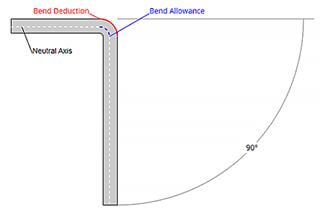
Calculate the Work Blank Size Accurately
Approach: Use precise measurements and calculations to determine the correct unfolding size of the sheet metal. This includes accounting for bend allowances and deductions based on material thickness and bend radius.
Tools: Utilize CAD software and advanced unfolding algorithms to ensure accuracy.
Increase Correction Process or Improve Bending Die Structure
Approach: Implement additional correction processes to compensate for material springback. This can include over-bending techniques or using specialized dies designed to minimize springback.
Tools: Invest in high-quality bending dies and consider using CNC press brakes that offer better control and repeatability.
Change Processing Methods or Improve Positioning
Approach: Evaluate and potentially change the processing methods to more precise techniques. Improve the positioning of the sheet metal during bending by using fixtures, clamps, or automated positioning systems.
Tools: Employ laser cutting for pre-bending hole creation and use automated positioning systems to ensure consistent placement.
12. Bending Line Not Parallel to Two-Hole Center
Cause Analysis:
When the bending height is less than the minimum bending height, the bending part tends to expand. This expansion can lead to misalignment, causing the bending line to not be parallel to the center of the holes.
Solutions:
Increase the Height of the Workpiece to be Bent
Ensure that the bending height meets or exceeds the minimum required bending height. This will help in maintaining the structural integrity of the workpiece and prevent unwanted expansion during the bending process.
Improve Bending Techniques
Tooling Adjustment: Use appropriate tooling that matches the material and thickness of the workpiece. Proper tooling can help in achieving precise bends.
Bend Sequencing: Plan the sequence of bends to minimize internal stresses and distortions. This can help in maintaining the alignment of the bending line with the hole centers.
Material Handling: Ensure that the workpiece is properly supported and aligned during the bending process. This can prevent shifts and misalignments.
Operator Training: Train operators on best practices for bending operations, including the importance of maintaining minimum bending heights and proper alignment techniques.
13. Deformation in Width After Bending
Cause Analysis:
Deformation in terms of width after bending, often manifesting as bow deflection, can significantly impact the quality and precision of the final workpiece. This issue typically arises due to inconsistent depth and shrinkage across the width of the workpiece, leading to torsion and deflection. The primary factors contributing to this problem include:
Inconsistent Material Properties: Variations in material thickness, hardness, and grain structure can cause uneven deformation during bending.
Improper Tooling Setup: Misalignment or wear in the bending tools can result in uneven pressure distribution.
Inaccurate Bending Parameters: Incorrect bending force, speed, or angle can exacerbate deformation issues.
Residual Stresses: Pre-existing stresses within the material can lead to unpredictable deformation when additional forces are applied.
Solutions:
To mitigate deformation in width after bending, several strategies can be implemented:
Increase Bending Pressure:
Rationale: Applying higher bending pressure can help achieve a more uniform deformation by overcoming material inconsistencies.
Implementation: Adjust the press brake settings to increase the force applied during the bending process. Ensure that the machine is capable of handling the increased pressure without causing damage to the tooling or the workpiece.
Increase Correction Process:
Rationale: Performing additional correction steps can help rectify any deformation that occurs during the initial bending.
Implementation: Introduce intermediate correction stages where the workpiece is checked and adjusted for any deviations. This can involve re-bending or using specialized correction tools to straighten the workpiece.
Ensure a Certain Angle Between Materials and Bending Direction:
Rationale: Aligning the material grain direction with the bending direction can reduce the likelihood of uneven deformation.
Implementation: Analyze the material grain structure and adjust the orientation of the workpiece so that the bending force is applied in a direction that minimizes deflection. This often means bending perpendicular to the grain direction.
Additional Recommendations:
Tooling Maintenance: Regularly inspect and maintain bending tools to ensure they are in good condition and properly aligned.
Material Selection: Choose materials with consistent properties and minimal residual stresses for critical applications.
Simulation and Testing: Use computer-aided design (CAD) and finite element analysis (FEA) to simulate the bending process and predict potential deformation issues before actual production.
14. Workpiece with Incision Causing Downward Deflection
Cause Analysis:
When a workpiece with an incision is processed, the material at the incision tends to open up, causing the two straight edges to move outward to the left and right. This movement results in a downward deflection at the bottom of the workpiece. This phenomenon is often observed in sheet metal processing, where the integrity of the material is compromised by cuts or incisions, leading to deformation.
Solutions:
Improve the Workpiece Structure
Reinforcement: Reinforce the areas around the incision to maintain structural integrity during processing. This can be achieved by adding temporary supports or using a more rigid material.
Design Optimization: Redesign the workpiece to minimize the impact of incisions. This can include altering the shape or adding features that distribute stress more evenly.
Increase Processing Allowance at Incisions
Connecting Incisions: Increase the processing allowance at the incisions to connect them temporarily. This means leaving a small bridge of material that keeps the edges together during bending. After the bending process is complete, these bridges can be cut off.
Pre-Bending Cuts: Perform initial cuts that do not fully penetrate the material, followed by the bending process. Once the bending is completed, finish the cuts to separate the parts.
Additional Considerations:
Material Selection: Choose materials with higher ductility and strength to reduce the likelihood of deflection.
Tooling Adjustments: Use specialized tooling that can support the workpiece better during processing, reducing the chances of deflection.
Process Parameters: Adjust the processing parameters, such as cutting speed and force, to minimize the stress on the workpiece.
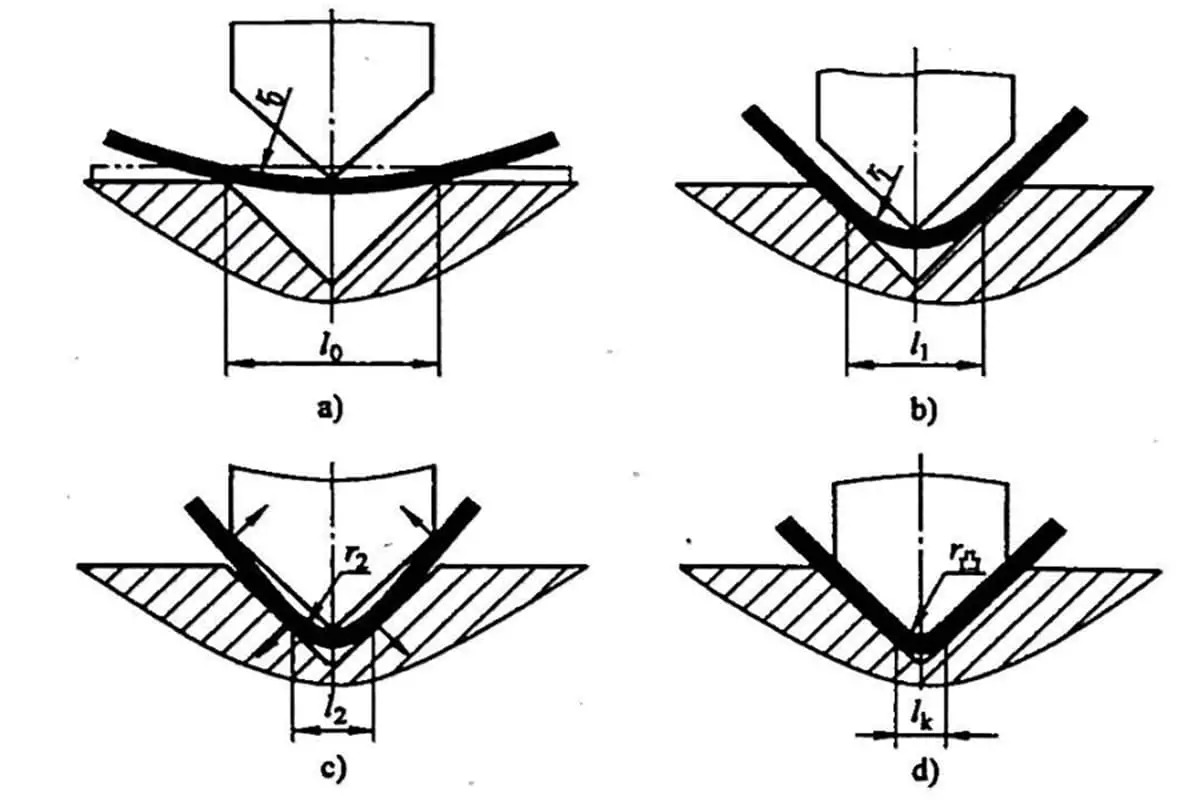
15. Slip Material During Processing
Cause Analysis:
In the process of selecting the bending die, it is common practice to choose a V-groove width that is 4 to 6 times the material thickness (T). However, slippage can occur if the size of the bend is less than half the width of the selected V-groove. This situation arises because the material lacks sufficient support within the oversized V-groove, leading to instability during the bending process.
Problem:
The primary issue here is that the V-groove selected is too large for the material being bent, which causes the material to slip during processing.
When the size of the material to be bent is less than half of 4 to 6 times T, it is essential to compensate for the excess space in the V-groove. This can be achieved through eccentric machining, where the material is positioned off-center to ensure better contact and support within the V-groove.
2. Padding Processing
Another effective solution is to use padding to fill the excess space in the V-groove. This padding provides additional support to the material, preventing slippage during the bending process.
3. Bend with a Small V-groove and Press with a Large V-groove
In situations where a small V-groove is necessary for the initial bend, but a larger V-groove is required for the final press, a combination approach can be used. Start by bending the material with a small V-groove to ensure stability and then press with a larger V-groove to achieve the desired bend radius.
4. Select a Smaller V-groove
The most straightforward solution is to select a smaller V-groove that is more appropriate for the material thickness and bend size. This ensures that the material is adequately supported throughout the bending process, reducing the risk of slippage.
16. Internal Bending Width and Standard Mold Considerations
Cause Analysis:
In the context of bending operations using a press brake, the internal bending width often needs to be narrower than the standard mold width. Here are the key factors and considerations:
Standard Width of the Lower Die: The lower die of a bending machine typically has a minimum standard width, often around 10mm. This is crucial for ensuring the die can accommodate the material being bent without causing damage or inaccuracies.
Material Thickness: For effective bending, the material thickness must be less than the minimum width of the lower die. If the material is too thick, it can lead to improper bending and potential damage to the equipment.
Bend Angle and Length: When bending at a 90-degree angle, the length of the bend must adhere to specific geometric constraints. The formula √2 (L + V / 2) + T helps determine the minimum length required for a proper bend, where:
𝐿L is the length of the bend.
𝑉V is the width of the V-die opening.
𝑇T is the material thickness.
Mold Fixation: To prevent displacement of the mold, which can lead to scrap material or safety hazards, the mold must be securely fixed on the mold base. This fixation should allow for no upward movement, ensuring stability during the bending process.
Solutions:
To address the issue of the internal bending width being narrower than the standard mold width, consider the following solutions:
Increase Bend Size:
Negotiation with Customer: Discuss with the customer the possibility of increasing the size of the bend. This can help in achieving a wider internal bend, making it compatible with the standard mold width.
Design Adjustments: Modify the design specifications to accommodate a wider bend, ensuring it fits within the standard mold parameters.
Special Processing of the Mold:
Custom Mold Fabrication: Create a custom mold specifically designed to handle narrower internal bends. This may involve specialized machining and design adjustments.
Enhanced Mold Features: Incorporate features that allow for precise bending of narrower widths without compromising the integrity of the mold or the material.
Use of Grinding Tools:
Precision Grinding: Employ grinding tools to achieve the desired internal bend width. While this method can increase processing costs, it offers a high degree of precision and can be effective for small-scale or specialized bending operations.
Cost-Benefit Analysis: Evaluate the cost implications of using grinding tools versus other methods. In some cases, the increased processing cost may be justified by the improved accuracy and quality of the bend.
17. Hole Proximity to Bending Line
Cause Analysis:
When a hole is positioned too close to the bending line in a sheet metal part, the bending process can cause the material around the hole to pull and distort. This issue is particularly pronounced when the distance from the hole to the bend line, denoted as 𝐿L, is less than a critical value. This critical value is typically between 4 to 6 times the plate thickness 𝑇T divided by 2. Mathematically, this can be expressed as:
𝐿<4𝑇/2 to 6𝑇/2
During the bending process, tensile forces act on the material, which can lead to pull-through and distortion if 𝐿L is insufficient. This is because the material around the hole is subjected to significant stress, causing it to deform.
Minimum Distance 𝐿L for Different Plate Thicknesses
The minimum distance 𝐿L for various plate thicknesses can be determined based on the standard mold’s groove width. This ensures that the material does not experience excessive stress during bending, preventing pull-through and distortion.
Solutions:
To mitigate the issue of holes being too close to the bending line, several solutions can be implemented:
Increase the Bend Size and Trim the Hem After Forming:
By increasing the bend size, the stress distribution around the hole can be improved, reducing the likelihood of pull-through. After forming, the hem can be trimmed to achieve the desired dimensions.
Expand the Hole to the Bend Line:
If the appearance and function of the part are not compromised, and with customer approval, the hole can be expanded to the bend line. This can help in distributing the stress more evenly.
Use Secant or Crimping Processing:
Secant or crimping techniques can be employed to modify the stress distribution around the hole, thereby reducing the risk of pull-through.
Eccentrically Process the Mold:
By eccentrically processing the mold, the stress concentration around the hole can be minimized, preventing distortion during bending.
Modify the Hole Size:
Adjusting the size of the hole can also help in reducing the stress concentration. This may involve making the hole larger or changing its shape to better distribute the forces during bending.
18. Analysis of Deformation in Bending Process
In the context of sheet metal processing, particularly during bending operations, the distance 𝐿L between the drawn edge and the bending line plays a crucial role in determining the quality of the bend. When this distance is too small, it can lead to undesirable deformations. Let’s delve deeper into the cause and potential solutions for this issue.
Cause Analysis:
When the distance 𝐿L between the drawn edge and the bending line is less than 4𝑇/2 to 6𝑇/2 (where 𝑇T is the plate thickness), the material is prone to deformation. This deformation occurs because the material comes into contact with the lower mold during the bending process. The insufficient distance does not allow the material to bend freely, leading to stress concentrations and subsequent deformation.
Solutions:
To mitigate this issue, several strategies can be employed:
1. Use Secant or Crimping Processing
Secant or crimping processing can help manage the material flow and reduce the stress concentrations that cause deformation. These methods involve creating a controlled deformation pattern that distributes the stresses more evenly across the material.
2. Modify the Material Size
Adjusting the dimensions of the material can help ensure that the distance 𝐿L is within the acceptable range. This might involve increasing the size of the blank or altering the design to provide more space between the drawn edge and the bending line.
3. Employ Special Mold Processing
Specialized molds can be designed to accommodate the specific requirements of the bending process. These molds can help control the material flow and reduce the likelihood of deformation by providing better support and reducing contact points that cause stress concentrations.
4. Eccentrically Process the Mold
Eccentric processing of the mold involves designing the mold in such a way that it compensates for the small distance 𝐿L. This might include off-center features or adjustments that allow the material to bend without coming into direct contact with the lower mold, thereby reducing the risk of deformation.
19. Long Flattening Side Rises After Flattening
Cause Analysis:
The long flattening edge may not adhere tightly during the flattening process, causing it to rise at the ends. This issue is largely dependent on the flattening position, so it is crucial to pay close attention to the positioning during the flattening process.
Solutions:
Pre-Bend the Upward Angle: Before bending the dead edge, first bend the upward angle as shown in the diagram. This pre-bending step helps in aligning the material properly, reducing the tendency of the edge to rise.
Flatten in Multiple Steps: Instead of attempting to flatten the edge in a single step, perform the flattening in multiple stages. This gradual approach allows for better control and reduces the risk of the edge rising.
Press the End First: Start by pressing the end of the material to bend the dead side down. This initial pressing helps in securing the material and prevents the edge from rising during subsequent flattening steps.
Flatten the Root Part: Focus on flattening the root part of the material first. Ensuring that the root is properly flattened provides a stable base, reducing the likelihood of the edge rising.
Precautions:
Attention to Detail: Pay close attention to the positioning and alignment of the material throughout the flattening process.
Quality Control: Regularly inspect the quality of the flattening process to ensure that the edges are adhering properly and not rising.
Tool Maintenance: Ensure that the tools and equipment used for flattening are in good condition and properly calibrated.
20. Large-Height Draw Bridge Fractures
Cause Analysis:
The primary cause of fractures in large-height draw bridges is the severe stretching and fracturing of the material. This can occur due to several factors:
Material Stretching and Fracturing: The high height of the draw bridge can cause the material to be excessively stretched, leading to fractures.
Insufficient Sharpening or Dull Mold Corners: If the special mold corners are not adequately sharpened, they can contribute to stress concentrations, leading to material failure.
Poor Material Toughness: Materials with low toughness are more prone to fracturing under stress.
Narrow Draw Bridge: A narrow draw bridge can concentrate stress in a smaller area, increasing the likelihood of fractures.
Solutions:
To address these issues and prevent fractures in large-height draw bridges, the following solutions can be implemented:
Lengthen the Process Hole: By lengthening the process hole on one side of the fracture, the stress distribution can be improved, reducing the likelihood of fractures.
Increase the Width of the Draw Bridge: A wider draw bridge can distribute the stress over a larger area, decreasing the risk of material failure.
Repair and Optimize Mold Corners: Repairing the special mold R angle and increasing the arc transition can help to reduce stress concentrations and improve the material’s ability to withstand stretching.
Add Lubricant: Applying lubricant to the draw bridge can reduce friction and the associated stress. However, this method has limitations:
It can make the surface of the workpiece dirty.
It is not suitable for aluminum (AL) parts and other materials where surface cleanliness is critical.
21. Size Changes During Special Mold Processing
Cause Analysis:
During special mold processing, the processing size can change due to several factors. One primary cause is the displacement of the workpiece. This displacement is often the result of a forward pressing force exerted during the processing. As a consequence, the small angle 𝐿L of the front portion of the workpiece increases. This change can lead to inaccuracies in the final dimensions of the processed workpiece.
Solutions:
To mitigate the issue of size changes during special mold processing, the following solutions can be implemented:
Remove Shadows in the Picture:
Ensure that the workpiece and the mold are clearly visible during processing. Shadows can obscure important details and lead to errors in positioning and alignment. Use adequate lighting and adjust the position of light sources to eliminate shadows.
Replace Worn Self-Positioning Parts:
Over time, the self-positioning parts of the mold can wear out, leading to inaccuracies in positioning. Regularly inspect these parts and replace them as needed. Using back-initiating structures can provide better positioning and reduce the likelihood of displacement.
Implement External System Analysis:
Although no search is needed, conducting an external system analysis can help identify other potential causes of size changes. This analysis can include examining the entire processing setup, including the machinery, tools, and environmental conditions.
22. Inconsistent Overall Size of Blanking
Cause Analysis:
Project Deployment Error: Mistakes during the initial setup and planning stages can lead to inaccuracies in the final dimensions of the blanking.
Incorrect Feeding Size: Errors in the material feeding process can result in deviations from the intended dimensions, affecting the overall size of the blanking.
Solutions:
Deviation Calculation and Distribution:
Calculate Deviation: Determine the total deviation from the intended size and calculate the deviation assigned to each bend.
Distribution Tolerance: Assess whether the calculated distribution tolerance falls within the acceptable range. If it does, the workpiece can be considered acceptable.
Adjusting V-Groove Size:
Size Too Large: If the overall size of the blanking is too large, use a smaller V-groove. This adjustment can help achieve the desired dimensions by reducing the material stretch during bending.
Size Too Small: If the overall size is too small, use a larger V-groove. This can help increase the material stretch, compensating for the smaller size and bringing it within the acceptable range.
23. Spalling or Loosening of the Draw-Hole After Riveting and Resulting Deformation
Cause Analysis:
Spalling:
Small R Angle of the Draw-Hole: A small radius (R) angle at the draw-hole can lead to stress concentration, causing the material to spall or chip away.
Excessive Burr on the Flange: Burrs, which are rough edges or protrusions left on the material after cutting or machining, can also contribute to spalling by creating additional stress points.
Loose Riveting:
Improper Alignment of Draw Holes: When the draw holes are not properly aligned, the rivet cannot secure the materials effectively, leading to a loose fit.
Deformation:
Misaligned Holes: Misalignment of holes during the riveting process can cause uneven stress distribution, resulting in deformation of the material.
Incorrect Riveting Method: Using an inappropriate riveting technique can also lead to deformation by not applying the necessary force uniformly.
Solutions:
Preventing Spalling:
Use a Center Punch with a Larger R Angle: A larger radius on the center punch can help distribute stress more evenly around the draw-hole, reducing the likelihood of spalling.
Attention to Burrs: Ensure that burrs around the draw-hole are minimized or removed during the flanging process to prevent stress concentration.
Ensuring Proper Riveting:
Increase Pressure and Deepen Broaching: Applying higher pressure and deepening the broaching process can help create a more secure fit for the rivet.
Use a Center Punch with a Larger R Angle: This can also help in achieving a better alignment and fit for the rivet.
Addressing Misalignment and Riveting Method:
Correct Hole Alignment: Ensure that all holes are properly aligned before riveting. This can be achieved by using precise measurement tools and alignment techniques.
Use Correct Riveting Method: Adopt the appropriate riveting method for the specific material and application. This might include using the correct type of rivet, applying the right amount of force, and ensuring uniform pressure distribution.
24. Skewed Riveting of the Stud or Deformed Workpiece After Riveting
Cause Analysis:
Workpiece Not Flattened During Processing
If the workpiece is not properly flattened before the riveting process, it can lead to misalignment and deformation.
Uneven Force or Excessive Pressure Applied to the Lower Surface
Applying uneven force or excessive pressure during riveting can cause the workpiece to skew or deform.
Solutions:
Flatten the Workpiece When Pressing the Stud
Ensure that the workpiece is thoroughly flattened before initiating the riveting process. This can be achieved by using appropriate flattening tools or techniques.
Use a Support Frame
Implementing a support frame can help maintain the alignment and stability of the workpiece during the riveting process. This reduces the risk of skewing and deformation.
Readjust the Pressure
Carefully adjust the pressure applied during the riveting process. Ensure that the pressure is evenly distributed to prevent any skewing or deformation.
Increase the Stress Range on the Lower Surface and Reduce the Force Range on the Upper Surface
By increasing the stress range on the lower surface and reducing the force range on the upper surface, you can achieve a more balanced force distribution. This helps in maintaining the integrity of the workpiece and prevents deformation.
Additional Recommendations:
Regular Maintenance and Calibration of Riveting Equipment
Ensure that the riveting equipment is regularly maintained and calibrated to provide consistent performance. This helps in applying the correct amount of force and pressure during the process.
Training for Operators
Provide adequate training for operators to ensure they understand the importance of proper alignment, pressure adjustment, and the use of support frames during the riveting process.
Quality Control Checks
Implement quality control checks at various stages of the riveting process to identify and rectify any issues early on. This helps in maintaining the overall quality of the workpiece.
25. Non-Parallel Sides After Offset Bending
Cause Analysis:
Incorrect Mold Calibration
If the mold is not calibrated correctly, it can lead to inaccuracies in the bending process, resulting in non-parallel sides.
Improper Adjustment of Upper and Lower Die Gaskets
The gaskets between the upper and lower dies play a crucial role in maintaining the alignment. If these gaskets are not adjusted properly, it can cause misalignment.
Non-Identical Upper and Lower Die Faces
The surfaces of the upper and lower dies must be identical to ensure uniform bending. Any discrepancies can lead to uneven bending and non-parallel sides.
Solutions:
Recalibrate the Mold
Ensure that the mold is correctly calibrated. This involves checking and adjusting the mold settings to ensure precision in the bending process.
Adjust the Gaskets
Increase or decrease the thickness of the gaskets between the upper and lower dies to achieve proper alignment. This adjustment helps in maintaining the parallelism of the sides.
Use Eccentric Processing for the Mold
Implement eccentric processing techniques to correct any misalignment issues. This involves adjusting the mold to compensate for any eccentricities in the bending process.
Ensure Identical Upper and Lower Mold Surfaces
Verify that the surfaces of the upper and lower molds are identical. This may involve machining or polishing the die faces to ensure they are uniform and free from any discrepancies.
Additional Tips:
Regular Maintenance and Inspection
Regularly inspect and maintain the molds and dies to ensure they remain in optimal condition. This includes checking for wear and tear and making necessary adjustments or replacements.
Use Precision Measuring Tools
Utilize precision measuring tools to check the alignment and parallelism of the sides after bending. This helps in identifying and correcting any issues promptly.
26. Deep Creases on Product Surface
Cause Analysis:
Small V-Groove in the Lower Die
Explanation: A smaller V-groove in the lower die can concentrate the bending force on a smaller area, leading to deeper creases on the product surface.
Small R Angle of the V-Groove in the Lower Die
Explanation: A smaller radius (R) angle in the V-groove can cause sharper bends, which increases the likelihood of deep creases forming on the material surface.
Material is Too Soft
Explanation: Softer materials are more susceptible to deformation and can easily develop deep creases under bending forces.
Solutions:
Use a Large V-Groove for Processing
Implementation: Switching to a larger V-groove in the lower die distributes the bending force over a wider area, reducing the depth of creases on the product surface.
Use a Mold with a Large R Angle
Implementation: Utilizing a mold with a larger radius angle in the V-groove creates smoother bends, minimizing the formation of deep creases.
Use Padding Bending (with Metal or Casting Polyurethane)
Implementation: Introducing padding materials such as metal or casting polyurethane during the bending process can help distribute the force more evenly, thereby reducing the depth of creases. Padding acts as a buffer, absorbing some of the bending stress and protecting the material surface.
27. Deformation Near the Bend After Bending
Cause Analysis:
The deformation near the bend after the bending process can be attributed to the machine operating at an excessively high speed. When the machine’s upward bending speed exceeds the speed at which the operator can manually hold and support the workpiece, it results in uneven force distribution and subsequent deformation. This discrepancy in speeds can lead to the workpiece not being properly aligned or supported during the bending process, causing unwanted deformation near the bend area.
Solutions:
To address this issue, the following solutions can be implemented:
Reduce the Machine’s Running Speed: By lowering the machine’s operating speed, the bending process can be more controlled and gradual. This allows the operator to better manage the workpiece, ensuring it remains properly aligned and supported throughout the bending process. A slower speed reduces the risk of sudden movements that can cause deformation.
Increase the Operator’s Hand-Holding Speed: Training the operator to increase their hand-holding speed can help in synchronizing their movements with the machine’s operation. This synchronization ensures that the workpiece is consistently supported, reducing the likelihood of deformation. However, this solution may be less practical as it relies heavily on the operator’s manual dexterity and reaction time.
Additional Recommendations:
Use of Support Tools: Implementing support tools such as back gauges, side supports, or automated handling systems can help in maintaining the workpiece’s position and alignment during the bending process. These tools can provide additional stability, reducing the reliance on the operator’s manual handling.
Regular Maintenance and Calibration: Ensuring that the bending machine is regularly maintained and calibrated can help in achieving consistent performance. Proper maintenance can prevent issues such as uneven force application or mechanical wear that could contribute to deformation.
Operator Training: Providing comprehensive training for operators on the correct handling techniques and the importance of synchronization with the machine’s speed can enhance their ability to manage the workpiece effectively. Training programs can also include best practices for using support tools and handling different types of materials.
28. Cracking of AL Parts During Bending
Aluminum (AL) parts are prone to cracking when bent due to the material’s unique crystal structure. This structure makes aluminum susceptible to breaking along parallel lines during the bending process.
Solutions to Prevent Cracking:
Adjust Material Orientation During Blanking:
Rotate the AL Material: When preparing the aluminum sheet for bending, it is crucial to rotate the material so that the bending direction is perpendicular to the grain (texture) of the aluminum. This adjustment helps to distribute the stress more evenly across the material, reducing the likelihood of cracks forming along the grain lines.
Increase the Radius of the Upper Die:
Enhance the R Angle: Increasing the radius (R angle) of the upper die used in the bending process can significantly reduce the stress concentration on the aluminum part. A larger radius allows for a more gradual bend, which minimizes the risk of cracking by reducing the strain on the material.
Additional Considerations:
Material Selection: Choosing an aluminum alloy with better ductility can also help in reducing the tendency to crack during bending. Alloys such as 5052 or 6061 are known for their good bending properties.
Preheating: Preheating the aluminum sheet before bending can improve its malleability, making it less prone to cracking.
Proper Tooling: Ensuring that the tooling is in good condition and free from defects can also contribute to a smoother bending process and reduce the risk of cracks.
As the founder of MachineMFG, I have dedicated over a decade of my career to the metalworking industry. My extensive experience has allowed me to become an expert in the fields of sheet metal fabrication, machining, mechanical engineering, and machine tools for metals. I am constantly thinking, reading, and writing about these subjects, constantly striving to stay at the forefront of my field. Let my knowledge and expertise be an asset to your business.
Have you ever wondered how sheet metal parts are designed and manufactured with precision? In this blog post, we'll dive into the fascinating world of bend allowance - a crucial…
Are you struggling to design accurate sheet metal parts? Unlock the secrets of the K-factor, a crucial concept in sheet metal fabrication. In this article, our expert mechanical engineer demystifies…
Have you ever struggled with accurately unfolding sheet metal parts? This article explores the art and science behind sheet metal unfolding calculations. Discover the key concepts, formulas, and techniques used…
Have you ever wondered how different materials affect sheet metal bending? In this insightful article, a seasoned mechanical engineer shares their expertise on the impact of material types, thickness, and…
What makes a flat sheet of metal transform into complex shapes with precision and accuracy? The answer lies in the intricate deformation process of sheet metal bending. This article dives…
How do you achieve precise bends in sheet metal? Understanding the molds and techniques behind this process is crucial. This article delves into various bending methods, from free bending to…
Attention all sheet metal fabricators and designers! Are you struggling to determine the optimal bending radius for your projects? Look no further! In this blog post, we'll dive into the…
Imagine bending sheet metal without leaving a single mark or scratch. In this article, we explore innovative techniques for mark-free sheet metal bending, addressing challenges like friction, material hardness, and…
Have you ever wondered how sheet metal designers ensure the accuracy of their designs? In this blog post, we'll dive into the fascinating world of sheet metal design and explore…