226 Solidworks Tips and Tricks
Have you ever struggled to navigate SolidWorks efficiently? This article unveils essential tips and tricks to streamline your workflow and enhance your design process. From mastering keyboard shortcuts to optimizing…
Why does one machine tool hum with precision while another jolts unpredictably? The answer lies in their hydraulic control systems. This article explores the critical differences between open-loop and closed-loop hydraulic control systems, demonstrating their distinct roles in machine tool performance. From basic directional control to sophisticated feedback mechanisms, you’ll learn how each system impacts precision, stability, and responsiveness. Dive into the mechanics and discover which system suits your needs for optimal control and efficiency.
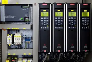
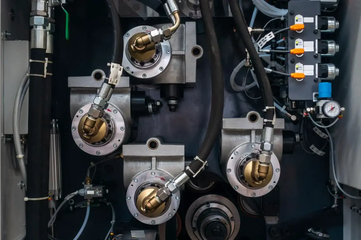
The hydraulic control system is composed of hydraulic control components and transducers. These components typically include hydraulic control valves, pumps, etc.
Hydraulic control technology is a crucial aspect of automatic control technology and is known for its unique characteristics, prominent benefits, and indispensable role.
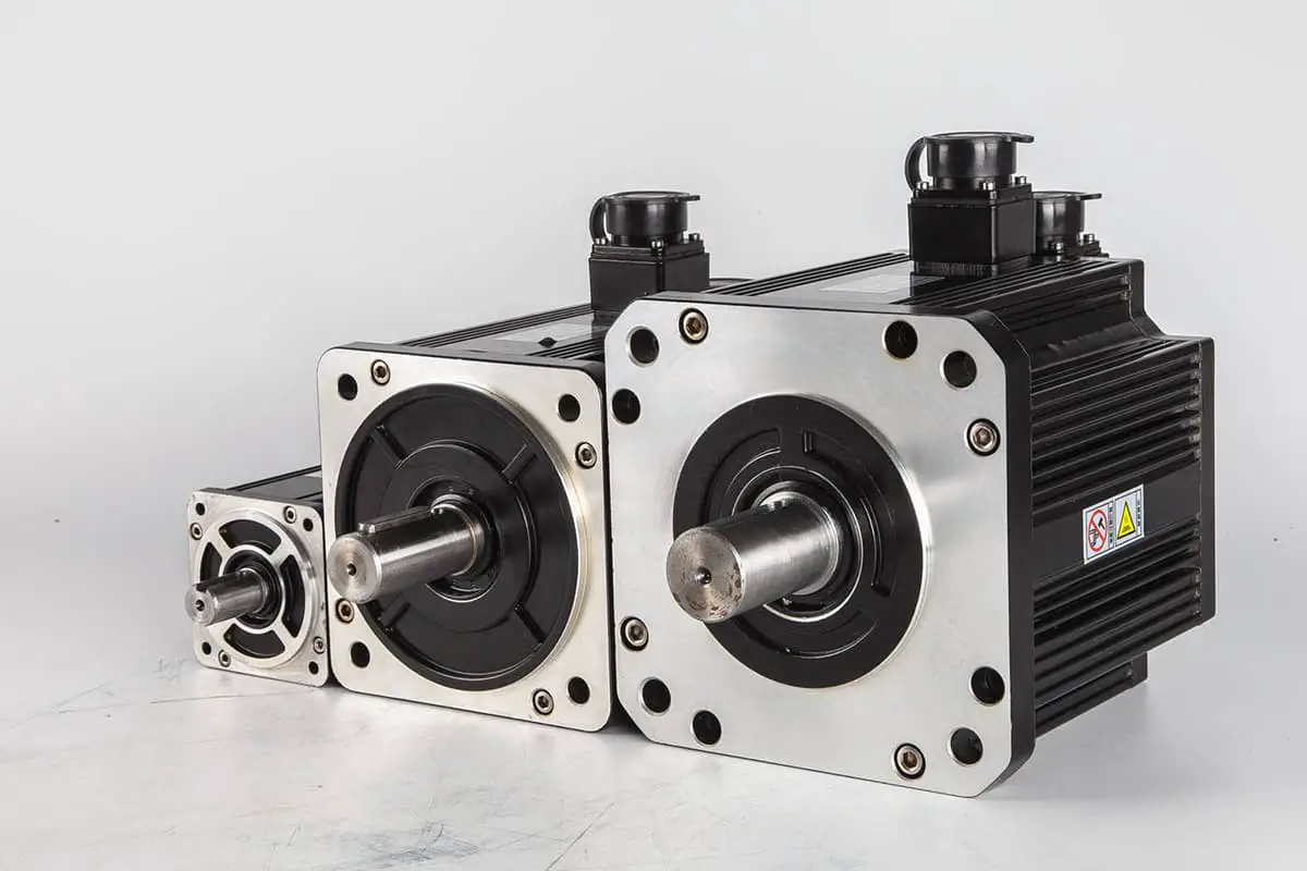
This technology represents the integration of electromechanical fluid and is demonstrated in the electrical hydraulic control system, which uses dynamic and negative feedback systems. The hydraulic control system is a dynamic system that integrates the mechanical, electrical, and hydraulic systems.
Hydraulic control technology has been widely adopted in various industries, including equipment manufacturing, automobile, aerospace, weapons, metallurgy, shipping, medical engineering, and more.
Just like the electromechanical control system, the hydraulic control system can be divided into open-loop and closed-loop control.
To illustrate the difference between the two, we will use the control of the machine tool movement beam as an example.
The machine tool movement beam is a common control object and serves as the workbench body of the machine tool. It is mounted on the slide guide of the machine tool body.
Different machine tools have varying performance requirements for the movement beam. For instance, the surface grinder’s motion beam only requires a steady horizontal reciprocating motion and does not require precise control of its displacement.
On the other hand, the NC machining center or CNC milling machine’s motion beam is used for precision feed motion, and its movement displacement must be precisely controlled to ensure proper machining quality.
In the case of the electro-hydraulic press brake, the ram’s movement distance also requires high accuracy to maintain consistent bending angles and avoid reduced bending effects.
To better understand the difference between open-loop and closed-loop hydraulic control, we will use the machine tool movement beam as a controlled object and build three common hydraulic control systems using electromagnetic directional valves, electromagnetic proportional directional valves, and electro-hydraulic servo valves as the main control components.
The hydraulic control scheme can be used for the horizontal reciprocating worktable of a typical surface grinding machine, as shown in Figure 1.1.
This hydraulic control system uses an electromagnetic directional valve.
A three-position four-way electromagnetic directional valve serves as the control unit, and a travel switch or proximity switch provides instructions. An electric relay forms a logical computing network.
This setup enables the control signal logic operation and power amplification, generating enough electromagnet to control the electromagnetic directional valve.
The valve core of the electromagnetic directional valve has three positions: left, middle, and right, and it can control the oil circuit breaker and switch.
Each valve port has only two states, fully open and fully closed, which classifies the electromagnetic directional valve as an electromagnetic hydraulic switch valve.
The electromagnetic directional valve can only start and stop the oil circuit operation to control the movement beam, but it cannot adjust the speed of the moving beam.
To regulate the speed of the moving beam, a throttle valve is installed in the hydraulic control system to perform throttle control.
By adjusting the valve opening, the throttle pressure difference can be regulated, which changes the oil flow back to the tank and indirectly adjusts the hydraulic oil inflow and outflow to the hydraulic cylinder, ultimately changing the beam’s speed.
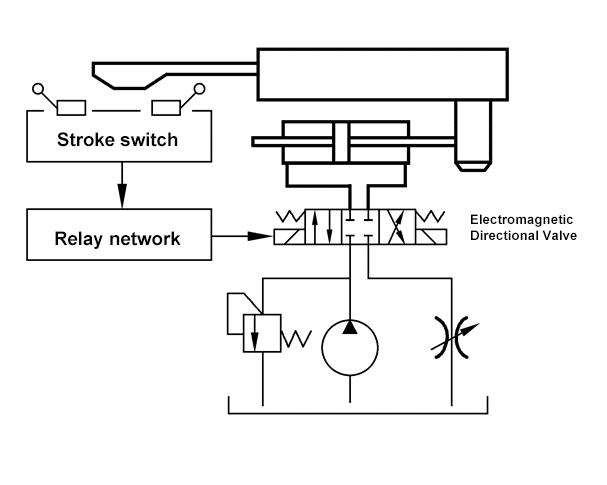
Fig. 1.1 Diagram for adopting electromagnetic directional valve to control system
The speed of the movement beam can only be controlled by the throttle valve and cannot be controlled by electric control. This results in sudden changes in speed and significant vibration of the beam.
The principle of the hydraulic control system using the electromagnetic directional valve is shown in Figure 1.2.
The control signal is generated by the travel switch and is a logic control unit (0 or 1).
The relay network performs a logic operation on the control signal and amplifies the power supply to the corresponding electromagnet, causing the corresponding valve core to move.
This results in the three positions of the valve core changing from left to right and outputs the hydraulic control flow, which drives the hydraulic cylinder and moves the machine tool movement beam.

Fig.1.2 Diagram for adopting an electromagnetic directional valve control system
The hydraulic control system consisting of an electromagnetic directional valve and relays can only generate simple control instructions.
The control signal is unidirectional and flows only in the forward direction of the controlled object.
This control system is an open-loop control system.
The response time of the control instruction to the controlled object is dependent on the response time of each component in the signal transmission path.
However, since the control instruction signal is simple, there is no issue with the control system not tracking the output instruction signal.
If a component is disturbed and produces a false movement, the system cannot automatically correct or compensate for the error.
The proportional electromagnetic directional valve is a high-performance, high-priced type of electromagnetic hydraulic valve.
For movement beam control that requires higher performance, such as numerical control surface grinding machines (where precise control of worktable displacement is not necessary), a proportional solenoid valve can be used as the control unit to form a low-impact, low-vibration hydraulic control system, as shown in Figure 1.3.

Fig.1.3 Diagram for adopting proportional electromagnetic directional valve to control system.
The proportional hydraulic valve uses an electric signal to control the valve core for gradual movement.
Therefore, to control the gradual change in valve opening, the pressure drop and flow rate of the proportional hydraulic valve can be adjusted, changing the ratio between flow and control signals.
The program controller generates electrical signals to control the moving beam, enabling the gradual change in electric signals to control and adjust the movement speed of the beam. This results in a smooth change in speed and direction of the beam’s movement with minimal impact.
The principle of the hydraulic control system using the proportional electromagnetic directional valve is shown in Figure 1.4.
The control signal is generated by the program controller and is an analog control signal (continuous electrical signal) that is amplified by a proportional amplifier to control the corresponding proportional electromagnet of the proportional solenoid valve.
This produces continuously adjustable displacement and continuously changing hydraulic pressure to control oil flow and drive the oil cylinder, thus realizing the movement of the machine tool beam.
In the hydraulic control system using the proportional electromagnetic directional valve, although a degree controller can be used to issue a continuous gradient control command signal, the control signal is unidirectional and flows only in the forward direction of the controlled object. This is an open-loop control system.
The command system can send a continuous gradient signal, and the system output can track the command signal, but the tracking accuracy is low, and the response speed is slow and dependent on the response time of the signal transmission components.
Errors caused by interference cannot be automatically compensated.

Fig.1.4 Diagram for adopting proportional electromagnetic directional valve to control system.
The movement of the NC machining center’s worktable is a critical part of the machining process, requiring high precision and fast response speed.
In this case, an electro-hydraulic servo control system can be used, with an electro-hydraulic servo valve serving as the control unit.
The electro-hydraulic servo valve is a high-performance hydraulic control unit with precise control and quick response speed, but it is expensive.
The electro-hydraulic servo valve is often used in electro-hydraulic closed-loop control systems, where the controlled object can temporarily be driven by open-loop control mode.
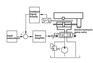
The hydraulic control system for the machine tool movement beam using an electro-hydraulic servo valve is shown in Figure 1.5.
The machine tool is equipped with a displacement sensor, which detects the position of the moving beam, generates a position voltage signal, and inputs the signal into the electronic control device after amplification.
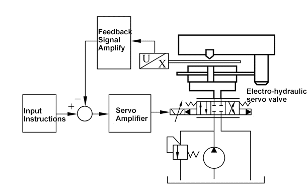
Fig.1.5 Diagram for adopting electro-hydraulic servo valve to control system.
The control device compares the current machine tool beam’s position voltage signal with the control instruction voltage signal to generate the deviation voltage signal.
The deviation signal is a continuous analog voltage that accurately and in real-time reflects the difference between the position of the machine tool beam and the control instruction (the desired position of the beam).
The deviation signal is amplified by the proportional amplifier, controlling the displacement of the torque motor in the electro-hydraulic servo valve and the high-precision, high-dynamic control valve core.
This generates the required hydraulic flow and pressure to drive the hydraulic cylinder movement and move the machine tool beam.
The movement of the beam is detected by the displacement sensor and sent to the electronic control device, forming a closed-loop control signal. This control system is referred to as closed-loop control.
The control process described above is shown in Figure 1.6.
The system is a closed-loop control structure.
In a closed-loop hydraulic control system, there is not only the forward control effect of the controller on the controlled object, but also a feedback effect from the controlled object to the controller.
The closed-loop control system has high precision, fast dynamic response, and automatic compensation for external interference.
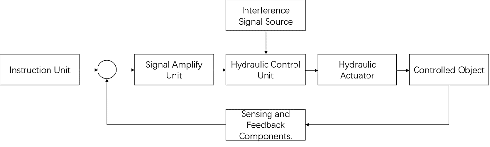
Fig.1.6 Diagram for adopting electro-hydraulic servo valve to control system.
Open loop hydraulic control and closed-loop hydraulic control are two kinds of basic control methods of hydraulic control.
1. Open loop hydraulic control.
The open-loop control system, which uses both common hydraulic valves and proportional hydraulic valves, has significant technical overlap with the hydraulic transmission system, as they often utilize similar types of hydraulic components and circuits.
The performance of the open-loop hydraulic control system is largely dependent on the performance of the hydraulic components.
Accuracy in the open-loop system is influenced by the accuracy of each component, and the response of the system is directly tied to the response of each component.
The open-loop hydraulic control system cannot control or compensate for changes in system output resulting from external disturbances or internal parameter variations.
In terms of design, the open-loop hydraulic control system is simple in structure and requires stability, making system analysis, design, and installation relatively straightforward. It can also benefit from the experience and knowledge gained from hydraulic transmission system design.
The main difference between the open-loop hydraulic control system and the hydraulic transmission system lies in their focus. The open-loop hydraulic system is typically used in conditions that require low accuracy control, minimal external disturbance, small changes in internal parameters, and allow for a slow response time.
In conclusion, the open-loop hydraulic control system is a basic, non-feedback control method. The controller only has control over the single direction of the controlled object and there is no inverse effect from the controlled object to the controller. Any errors caused by interference cannot be compensated automatically.
Due to the low accuracy and slow response of the open-loop control system, it is generally not recommended to use a servo valve, which has high requirements for working conditions and is high-priced and high-performing, in the construction of an open-loop control system.
2. Closed-loop hydraulic control.
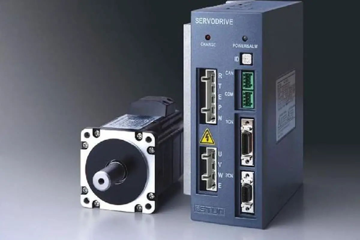
The closed-loop hydraulic control system often employs an electro-hydraulic servo valve or a direct drive valve (DDV) as its control unit.
Electro-hydraulic servo valves and direct drive valves are high-performance hydraulic control components that have closed-loop feedback control systems, leading to high precision and fast response speeds.
The closed-loop hydraulic control system is also referred to as a hydraulic feedback control system, which operates based on the principle of feedback.
The basic concept of feedback control is to eliminate or reduce deviations through the use of deviation.
The feedback control system functions by comparing information about the controlled object detected by the feedback unit with the control instructions from the system instruction unit, producing a deviation signal.
This deviation signal is amplified and used to drive a high-power hydraulic control valve, which in turn controls the hydraulic actuator and the controlled object.
The closed-loop hydraulic control system forms a closed loop, making it more complicated to analyze, design, and commission than open-loop systems. However, its high control accuracy and strong anti-interference ability make it a worthwhile investment.
Closed-loop control (feedback control method) allows for the construction of a control system with high precision and anti-interference abilities, even if the hydraulic components used have lower precision and weaker anti-interference abilities.
Additionally, existing hydraulic components can be utilized to achieve better control system performance and control effects through closed-loop control.
Feedback control offers advantages that cannot be achieved through open-loop control.

As the founder of MachineMFG, I have dedicated over a decade of my career to the metalworking industry. My extensive experience has allowed me to become an expert in the fields of sheet metal fabrication, machining, mechanical engineering, and machine tools for metals. I am constantly thinking, reading, and writing about these subjects, constantly striving to stay at the forefront of my field. Let my knowledge and expertise be an asset to your business.