1. General provisions
1.1 In order to reduce energy consumption and extend the service life of the nozzle and electrode, “low-grade” cutting should be used as much as possible when cutting thin workpieces.
1.2 When the “thickness selection” switch is set to “high grade”, non-contact cutting should be used for cutting (except in special circumstances) and water cutting torch should be prioritized.
1.3 When it is necessary to switch the “thickness selection” switch position, the main power switch must be turned off first to prevent damage to the machine parts.
1.4 When installing, disassembling or moving the host machine, the power supply must be turned off first before proceeding to avoid danger.
1.5 After turning off the main power switch, the attachments and components on the host machine (such as cutting torches, cutting ground wire, electrodes, nozzles, distributors, pressure caps, protective covers, etc.) can be installed or removed. Avoid repeatedly and quickly turning on the cutting torch switch to prevent damage to the arc ignition system or related components.
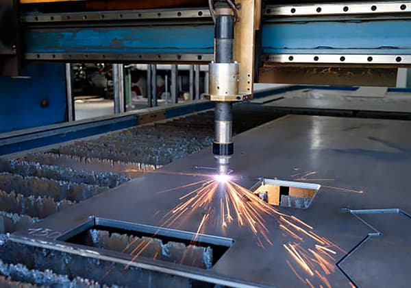
1.6 When it is necessary to start arc cutting from the middle of the workpiece, and the stainless steel is ≤20mm thick, direct perforation cutting can be used. The method is: place the cutting torch on the starting point of the cut, and make the axis of the cutting torch nozzle at an angle of about 75° with the surface of the workpiece.
Then, turn on the cutting torch switch to ignite the arc for perforation; at the same time, slowly adjust the angle between the nozzle axis and the workpiece surface until it reaches 90° when cutting through the workpiece.
After cutting through the workpiece, normal cutting can be performed along the direction of the cut. However, if it is necessary to use perforation cutting beyond the thickness mentioned above, a small hole (diameter not limited) must be drilled at the starting point of the cut, and the arc must be ignited for cutting from the small hole.
Otherwise, it is easy to damage the cutting torch nozzle.
1.7 The continuous working rate of the host machine is 70% (“thickness selection” switch set to low grade, continuous working can be close to 100%). If the continuous working time is too long and the temperature of the host machine is too high, the temperature protection system will automatically shut down, and it must be cooled for about 20 minutes before continuing to work.
1.8 When the compressed air pressure is lower than 0.22MPa, the equipment should immediately enter the protection shutdown state. At this time, the gas supply system should be inspected and the fault should be eliminated before the pressure can be restored to 0.45MPa before continuing to work.
1.9 If there is a phase loss in the three-phase input power supply, the host machine cannot work properly. For some models, the “phase loss indication” red light is on. The fault must be eliminated before normal cutting can be performed.
1.10 For water-cooled models, the water tank must be filled with tap water and the power plug of the water pump should be plugged in.
1.11 Rotate the power switch to the “on” position. If the “low air pressure” indicator light is on, adjust it to 0.45MPa as required. Then the “low air pressure” indicator light will go off. The direction of the fan should follow the indication. The rotation direction of the water pump of the water-cooled machine should meet the requirements. Otherwise, the “low water pressure” indicator light will turn on and the input power phase should be adjusted.
1.12 According to the thickness of the workpiece, turn the “thickness selection” switch to the corresponding position, and choose the appropriate cutting torch. There are many specifications for the cutting torch from small to large according to the usage range. It is forbidden to exceed the rated current range, otherwise damage will occur. Place the cutting torch at the starting point of the workpiece and press the cutting torch switch. If it does not ignite, press the cutting torch switch again. After successful arc ignition, start cutting.
1.13 Every four to eight hours of work (the interval time depends on the dryness of the compressed air), loosen the drain screw of the “air filter pressure reducer” as required to release the accumulated water to prevent too much water from entering the machine or cutting torch and causing malfunctions.
1.14 When the water cooling system is circulating poorly, the host machine will enter the protection shutdown state. At this time, follow the methods described in the relevant sections of this text for inspection and troubleshooting. Only when the water pressure returns to normal and the water return port of the water tank flows smoothly can the water-cooled cutting torch continue to be used.
1.15 When working in cold environments, attention must be paid: when the ambient temperature is below freezing point, water cooling should not be used for cutting. Otherwise, the water cooling system will not work properly and the water-cooled cutting torch may be damaged.
2. Preparation before operation
2.1 After connecting the equipment (please pay special attention to connecting the safety grounding wire), carefully inspect it. If everything is normal, the next step can be taken.
2.2 Close the power switch and supply power to the host machine.
Note: the input AC current is about 65A, which cannot be too small, otherwise the host machine will not work properly. At the same time, check that the fan inside the host machine meets the requirements. Otherwise, adjust the input power phase until it matches the rotation direction.
2.3 Put the “power switch” of the host machine in the “on” position. At this time, the “power indicator” light is on. However, the “phase loss indicator” light should not be on, otherwise there may be a phase loss in the three-phase power supply, and it should be checked and resolved.
Note: If the host machine shell is not properly grounded, the phase loss indicator light may display an incorrect result.
2.4 Supply air to the host machine and place the “test air” and “cutting” switches in the “test air” position. At this time, compressed air should be sprayed from the cutting torch nozzle. Test for three minutes during which the “low air pressure” red light should not turn on. Check that the pressure gauge on the “air filter pressure reducer” should not indicate less than 0.42MPa. Otherwise, it indicates that the gas source pressure is less than 0.45MPa, or the flow rate is less than 300L/min. It may also be due to the gas supply pipeline being too small, and the gas pressure drop being too large.
If there are the above problems, they should be checked and resolved. Also, please note whether the “air filter pressure reducer” is misaligned. If it is, it should be readjusted. The adjustment method is to rotate the handle clockwise to increase pressure, and counterclockwise to decrease pressure. Adjust the indicator value on the pressure gauge to 0.42MPa. If the gas supply is normal, the “low air pressure” indicator light will go off. At this point, please place the “cutting” and “test air” switches in the “cutting” position.
2.5 Safety Checks Before Use
- The cutting machine should operate in a dry, normal temperature environment, avoiding strong sunlight, rain, dust, corrosive gases, and areas with high air flow.
- The host machine should be placed at least 0.3 meters away from surrounding objects, with the cooling fan operating normally to maintain good ventilation.
- Check that the external power supply is accurate and correct.
- Confirm that the workpiece grounding cable is clamped to the workpiece.
- Connect the air source and discharge any accumulated water.
- Check that the power switch is in the off position.
- Close the main power switch of the power grid, the cooling fan starts to rotate, and the correct direction of the fan should blow into the host machine.
- Switch the power switch on the back to the “ON” position, the power indicator light will be on.
- Open the air control valve, adjust the pressure and air flow rate to the 0.4 MPa (Megapascal) position, and let the gas circulate for a few minutes to remove any condensate in the cutting torch.
- Set the appropriate cutting current according to the material, thickness, and process requirements of the workpiece.
- Upon pressing the switch on the cutting torch, the solenoid valve will activate. You will hear the sound of high-frequency spark discharge inside the host machine, at the same time, the plasma arc will spray out from the nozzle of the cutting torch.
3. Operation procedures
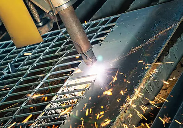
3.1 Manual non-contact cutting
3.1.1 Roll the cutting torch wheel into contact with the workpiece and adjust the distance between the nozzle and the workpiece plane to 3-5mm. (When the host machine is cutting, turn the “thickness selection” switch to the high gear).
3.1.2 Turn on the cutting torch switch to ignite the plasma arc. After cutting through the workpiece, move at a uniform speed in the cutting direction. The cutting speed should be fast but not too slow. Too slow will affect the quality of the cut and may even cause arc termination.
3.1.3 After cutting, turn off the cutting torch switch, and the plasma arc will extinguish. At this time, compressed air will spray out after a delay to cool the cutting torch. After a few seconds, the air spraying will automatically stop. Move the cutting torch away to complete the entire cutting process.
3.2 Manual contact cutting
3.2.1 Turn the “thickness selection” switch to the low gear for single thin plate cutting.
3.2.2 Place the cutting torch nozzle at the starting point of the workpiece to be cut, turn on the cutting torch switch to ignite the plasma arc, and cut through the workpiece. Then move uniformly along the cutting seam direction.
3.2.3 After cutting, open and close the cutting torch switch. At this time, compressed air is still spraying out. After a few seconds, the air spraying will automatically stop. Move the cutting torch away to complete the entire cutting process.
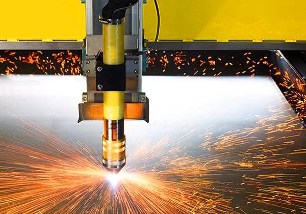
3.3 Automatic cutting
3.3.1 Automatic cutting is mainly suitable for cutting thicker workpieces. Select the position of the “thickness selection” switch.
3.3.2 After removing the cutting torch wheel, connect the cutting torch to the semi-automatic cutting machine firmly. The connecting parts are included in the random accessories.
3.3.3 Connect the power supply of the semi-automatic cutting machine and install the guide rail or radius rod according to the shape of the workpiece (use a guide rail for straight line cutting, and choose a radius rod for cutting circles or arcs).
3.3.4 If the cutting torch switch plug is removed, replace it with a remote control switch plug (included in the random accessories).
3.3.5 Adjust the appropriate walking speed according to the thickness of the workpiece. Set the “reverse” or “forward” switch on the semi-automatic cutting machine to the cutting direction.
3.3.6 Adjust the distance between the nozzle and the workpiece to 3-8mm, and adjust the center position of the nozzle to the starting strip of the workpiece cutting seam.
3.3.7 Turn on the remote control switch, cut through the workpiece, turn on the power switch of the semi-automatic cutting machine, and start cutting. At the initial stage of cutting, pay attention to the cutting seam and adjust to the appropriate cutting speed. Pay attention to whether both machines are working properly at all times.
3.3.8 After cutting, turn off the remote control switch and the power switch of the semi-automatic cutting machine. At this point, the entire cutting process is complete.
3.4 Manual circle cutting
According to the material and thickness of the workpiece, choose the single machine or combined machine cutting method, and select the corresponding cutting method. Tighten the crossbar from the random accessories on the cutting torch holder screw hole.
If one length is not enough, connect them one by one until the required radius length is reached and tighten them. Then, adjust the top to the distance between the cutting torch nozzle according to the radius length of the workpiece (taking into account the width of the cutting seam).
After adjustment, tighten the top fastening screws to prevent loosening and loosen the holding bracket fastening screws.
At this point, you can start cutting circles on the workpiece.
3.5 Operating steps
1. The flow rate of the air compressor used should be no less than 0.3m3/min, with a working range of 0.4~0.8MPa.
2. When initiating arc cutting, start from the edge of the workpiece. For workpieces that must be cut from the middle, first drill a small hole, then start the arc from the edge of the hole.
Turn on the power switch, allow the gas to flow for several minutes to remove condensation from the cutting torch, then begin cutting.
The nozzle of the cutting torch should touch the workpiece (if it’s a non-contact torch, the nozzle should be 3~5mm away from the workpiece). Press the cutting torch switch, wait for the plasma arc to automatically ignite, and the cutting officially begins.
During the cutting process, ensure the cutting speed is sufficient to cut through the workpiece. Cutting too quickly can result in incomplete cuts and might cause backslag to damage the nozzle, while cutting too slowly can lead to the nozzle overheating and reduce its lifespan, widen the cut, increase slag, and potentially cause arc interruption.
When stopping the cut, first release the cutting torch switch, then move the torch away from the workpiece.
3. Regularly check the motor and nozzle. If there is serious wear, replace them promptly to avoid affecting the cutting thickness and width. If the alloy wire in the electrode is consumed by more than 2.0mm or cannot initiate an arc, the electrode can be installed in reverse or replaced.
The output voltage of the cutting machine is very high.
When assembling or replacing the electrode or nozzle, you must turn off the power and wear protective gloves. Screw the electrode and nozzle vertically upward and tighten again after two or three minutes of use.
IV. Safety Precautions
1. Operators must pass relevant theoretical and practical training and examinations before operating this equipment.
2. Cutting work should be done in a well-ventilated environment. If ventilation is poor or the work is being done in a container, effective measures to enhance ventilation should be taken.
3. After the cutting machine is powered on, do not disassemble the casing or touch electrified parts (including the nozzle).
4. Before replacing parts of the cutting torch, the main power supply must be cut off.
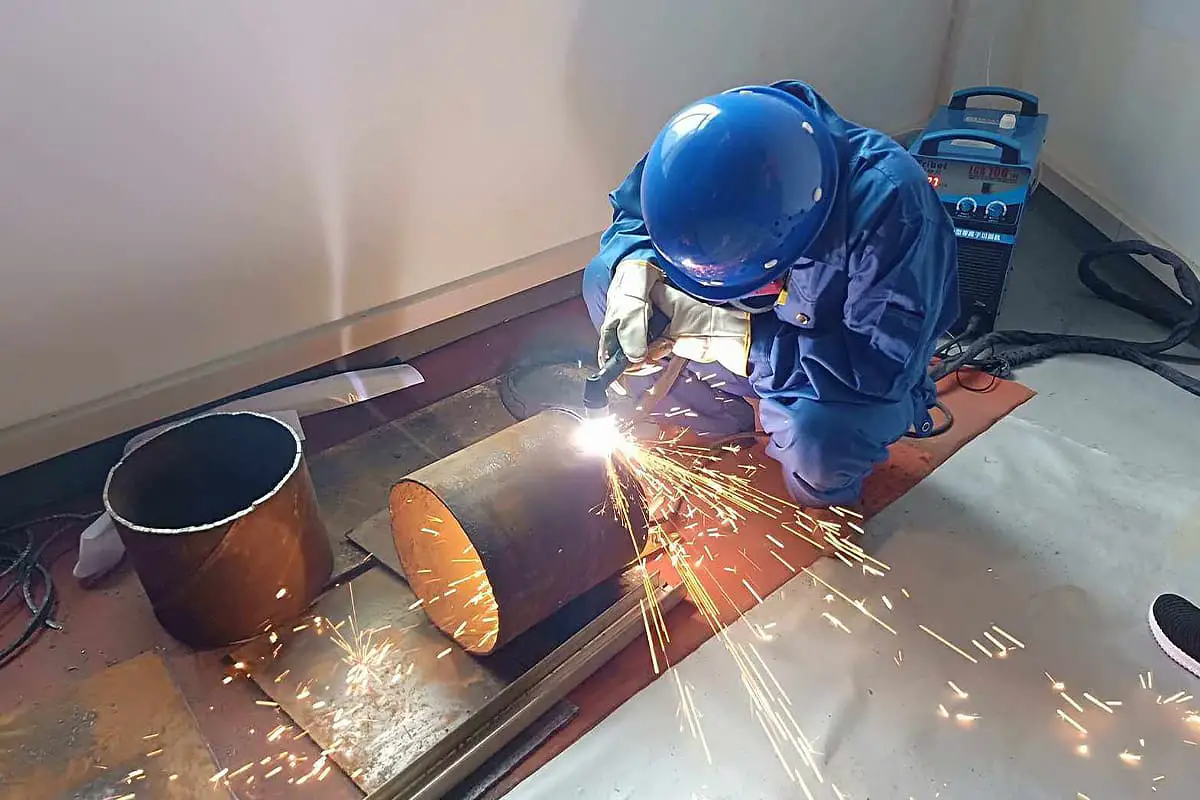
5. Before work, operators should wear protective clothing, gloves, shoes, hats, and light-colored face shields or UV-protective glasses.
6. The cutting site should not contain any flammable or explosive items.
7. During operation, ensure the cutting torch’s hose and cable are not damaged, and prevent sparks from damaging the main body of the cutting machine, accessories, or other items.
8. When the cutting machine is not in use, turn off the power first, then the gas supply.
9. Regular checks should be made to maintain the machine’s good condition and ensure a good ground connection.
V. Maintenance and Overhaul
1. Maintenance
1. All maintenance and repairs must be carried out with the power supply fully disconnected. Ensure that the power plug has been removed before opening the machine case.
2. Perform regular maintenance on the main machine once a month by blowing away dust with dry, clean compressed air.
3. Inspect and tag once every quarter.
4. The pressure of the compressed air should be around 0.4 MPa (megapascal). Too low or too high can potentially damage the small components within the cutting machine.
5. Carry out a check on the internal circuit connections of the cutting machine once a month to ensure that the connections are correct and the connectors are secure (especially insert connectors or components). If any rust or looseness is found, use sandpaper finer than P120# to grind away the rust layer or oxide film, re-connect, and secure them.
6. Avoid liquids or steam from entering the main machine. If such situations occur, dry the inside of the main machine promptly. Then use a megohmmeter to measure the insulation condition of the cutting machine (mainly between the external connection points). If there are no abnormalities, you may continue to operate the machine.
7. If the main machine is not used for over a month, clean it, package it, and store it in a dry location.
2. Overhaul
(1) Confirm that the air switch is closed
1. The display screen does not show anything, and the fan does not rotate.
2. Confirm the power in the input cable connection.
3. Confirm there is no phase loss in the power supply.
(2) Check if there are any poor contacts in various internal connections
1. The display screen and fan rotation are normal.
2. The control wire on the cutting torch is broken or the micro-switch is damaged; the button on the cutting torch does not function.
3. The control circuit is damaged (contact the supplier or manufacturer).
(3) Check if the high voltage package has been punctured
1. The IGBT is damaged; the abnormal indicator light is on, but the display screen is normal.
2. The fast recovery rectifier tube is damaged; the fan rotation is normal.
3. The control board is faulty.
4. The feedback circuit is faulty (the abnormal indicator light is on).
(4) There are issues in the arc initiation part
1. The discharge nozzle is too far away or there is adhesion; the fan rotation and display screen are normal.
2. The high voltage package is damaged; the solenoid valve operates, but there is no arc maintenance output, indicating an anomaly.
3. The arc initiation relay is damaged; the indicator light is not on.
4. The control circuit is faulty.
5. The feedback circuit is faulty, and the indicator light is damaged.
(5) Issues with the Quality of the Air Switch
1. The air switch cannot be closed.
2. The silicon bridge is damaged and needs to be replaced.
3. Check if there is a short circuit inside the machine.