Achieving Flawless CNC Flame Cutting for Thick Plates
How can manufacturers ensure flawless cuts in ultra-thick steel plates? This article delves into the critical process of CNC flame cutting, highlighting the challenges, such as potential cutting defects and material loss, and providing solutions to optimize gas supply, support frames, and cutting programs. By understanding these intricacies, readers will gain valuable insights into achieving precise and efficient cuts, ensuring high-quality results in large-scale manufacturing.
With the advent of large-scale equipment and the increasing utilization of steel over cast materials, ultra-thick plates have become increasingly prevalent in equipment manufacturing.
Flame cutting is the initial stage in the manufacture and processing of structural components.
Given the irreversible nature of flame cutting, the CNC flame-cutting process for ultra-thick plates has become a crucial technology for large equipment manufacturers.
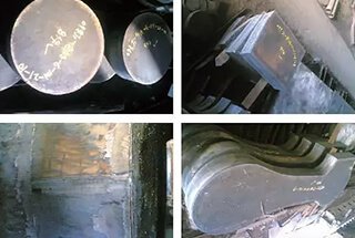
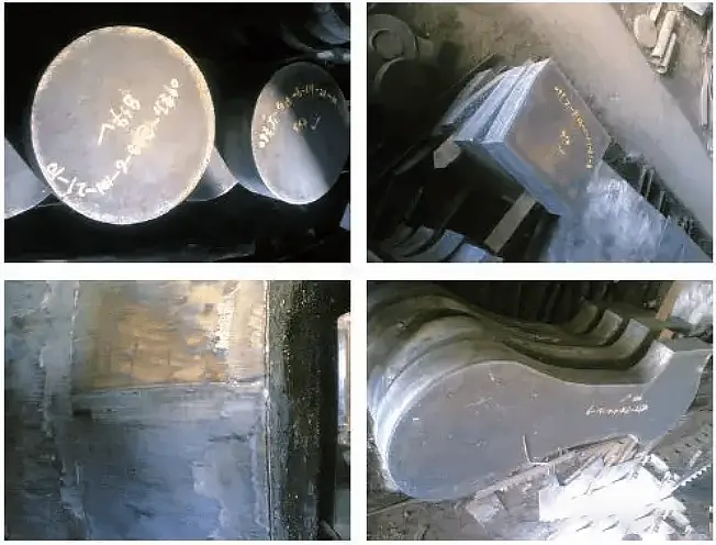
Figure 1
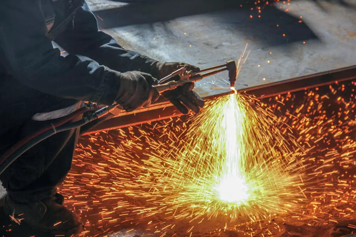
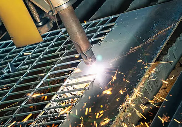
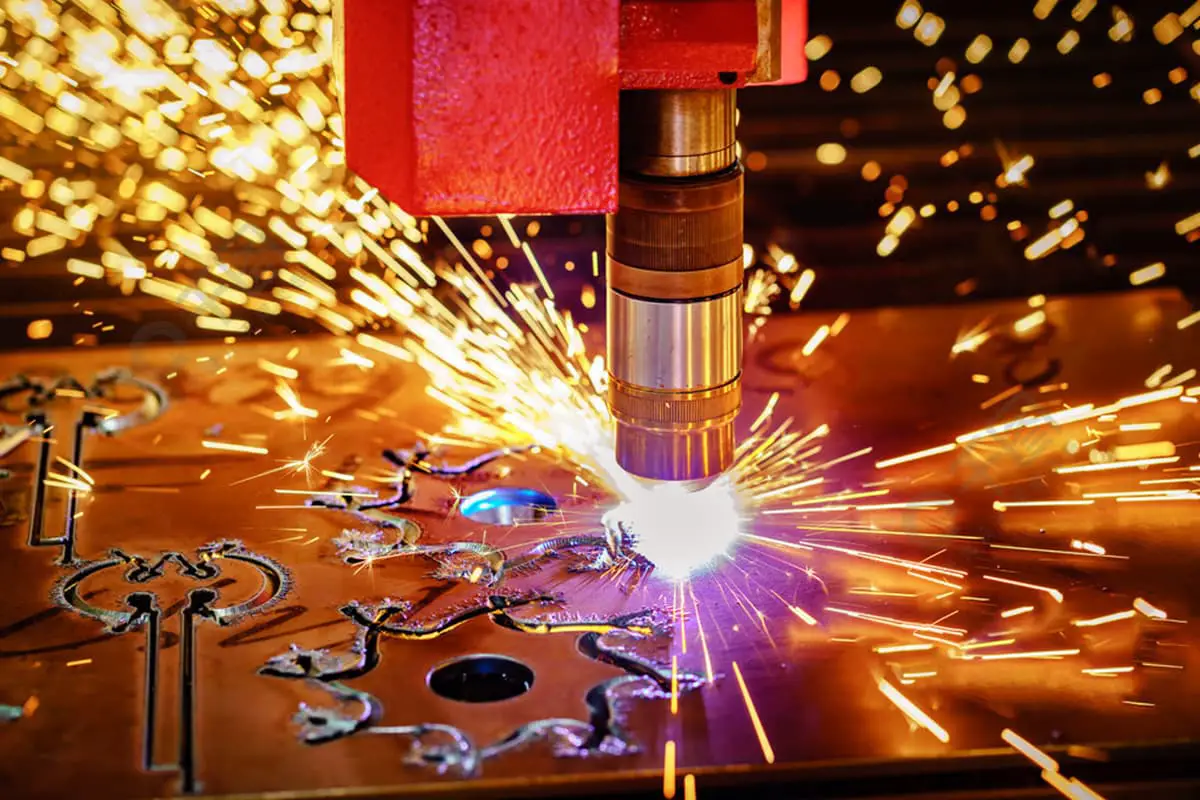
1. Characteristics of flame cutting of ultra-thick plate
Oxygen and Acetylene for Ultra-Thick Plate Cutting
The cutting of ultra-thick plate parts requires a large amount of oxygen and acetylene, as these parts are usually larger in size. To ensure a smooth and efficient cutting process, it is crucial to have a continuous and stable supply of these gases.
Large Size and Weight of Ultra-Thick Plates
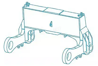
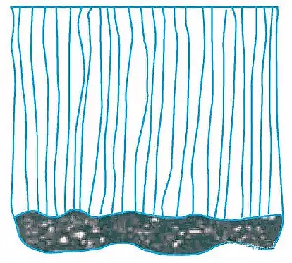
As an example, a 220mm x 2200mm x 8000mm thick plate weighs approximately 30 tons. Additionally, the weight of individual parts can be quite substantial, with the upper connecting rod number 9 steel plate, for instance, weighing more than 4 tons (refer to Figure 1).
Risk of Cutting Defects
Ultra-thick plates are more prone to cutting defects, such as impervious cutting, compared to regular plates.
Large Material Scrap Loss
The significant material loss during the edging process of ultra-thick plates makes it difficult to reuse the cut-off edges.
Cutting Distortion
The heat generated during the cutting process can cause deformation in the steel plate and result in deviation from the desired dimensions. Furthermore, sudden bouncing of the plate under high stress can lead to safety hazards. To prevent these quality and safety issues, it is essential to consider the cutting distortion when formulating the cutting process.
2. Ultra-thick plate cutting section is prone to quality defects
(1) Upper Edge Cutting Defects
The upper edge of the cut collapses or drops in the form of molten strings, resulting in rounded corners collapsing due to the upper edge of the slit melting too quickly.
Possible causes:
Thick refractory scale on the steel surface;
Slow cutting speed and excessive preheating flame;
Incorrect height between the cutting nozzle and the workpiece, large size of the cutting nozzle, and excess oxygen in the flame.
As illustrated in Picture 2.
Figure 2
(2) Poor Flatness of the Cutting Surface
① There is a concave defect under the edge of the cut section (refer to Figure 3). Additionally, the upper edge exhibits varying degrees of melting collapse.
This can be attributed to high cutting oxygen pressure or excessive height between the cutting nozzle and the workpiece, as well as a clogged cutting nozzle that causes wind interference.
② The cutting section has excessive roughness.
This may be due to excessive cutting speed or impurities in the steel plate that impact its formation.
As shown in Figure 3.
Figure 3
(3) Poor Verticality
① The width of the cutting seam varies, being narrow at the top and wide at the bottom or vice versa, due to a fast or slow cutting speed, a clogged cutting nozzle that interferes with the wind line, and inadequate or excessive cutting oxygen that leads to insufficient or excessive metal burning.
② The cutting torch creates an oblique angle that is not perpendicular to the workpiece surface or the wind line is incorrect.
(4) Lower-Edge Cutting Defects
① There is depression near the lower edge and the lower edge melts into rounded corners because of a fast cutting speed, a clogged or damaged cutting nozzle, and blocked or deteriorated air line.
② The removal of slag on the cut surface or lower edge is difficult due to factors such as a fast or slow cutting speed, a small cutting nozzle, low cutting oxygen pressure, excess gas in the preheating flame, a corroded or dirty steel plate surface, excessive height between the cutting nozzle and the workpiece, and a strong preheating flame. Additionally, a high content of alloy can result in slag formation on the cross section and bottom edge (refer to Figure 4).
Figure 4
(5) Cracks
Microcracks appear in the cutting section or heat-affected zone due to high carbon equivalent in the steel plate that results in high crack sensitivity, coupled with the lack of proper preheating and slow cooling measures.
(6) Deformation
Local heating of the steel plate during cutting causes material shifting deformation, leading to dimensional deviation of the cut parts and affecting their quality.
As illustrated in Figure 5.
Figure 5
3. Cutting process
(1) Cutting Gas Supply System
To maintain a consistent and reliable supply of oxygen and acetylene gas, multiple gas bottles can be utilized in parallel. This will ensure a stable and uninterrupted flow of acetylene gas.
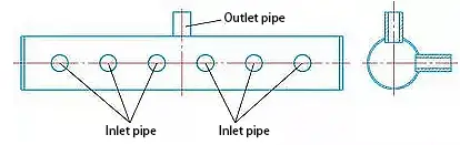
A parallel gas supply package can be created as shown in Figure 6. A φ100mm steel pipe is utilized as the air bag, and both ends are securely welded with steel plates.
Six intake pipes and one air outlet pipe are drilled into the steel pipe, taking care to ensure proper welding quality and avoiding any air bag leaks.
A gas-tight ball valve and a connecting device should be added to each air inlet and outlet.
Figure 6
(2) Cutting Support Frame
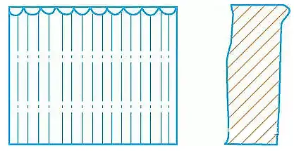
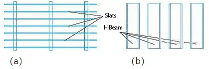
Due to the large size and weight of the thick plate, which has a maximum weight of 30 tons, and the substantial size and weight of individual parts, with a maximum weight of 4 tons, the original CNC cutting machine support frame cannot meet the cutting requirements as it provides insufficient support for the slats (as shown in Figure 7a).
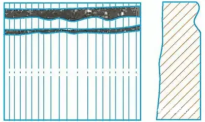
To ensure stable support of the frame, modifications to the support frame are necessary. After careful analysis, research, and discussion, it was decided to utilize waste H-shaped steel as the thick plate support frame.
(A) Support Frame Before Transformation
(B) Support Frame After Transformation
Figure 7
(3) Cutting Program Optimization
Initially, lead-out point processing is introduced.
The biggest challenge in cutting ultra-thick boards (up to 220mm) is ensuring a quality cut, especially the positioning of the lead-in and lead-out points of the parts, which often leads to cutting defects.
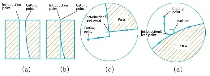
As illustrated in Figures 8a and 8b, thick plate cutting points are often not vertical.
When the cutting point coincides with the lead-in point, if the cutting line turns at this moment, the root will not be cut, causing defects due to fractures from the weight of the parts.
To prevent such defects from occurring, optimizing the lead-in and lead-out in the cutting process can be an effective solution.
Figure 8
Secondly, if proper care is not taken regarding the direction during the cutting process, it can cause deformation of the parts. This is because the expansion force will push the part away, leading to inconsistencies in the size of the part and the program size.
To address this problem, our analysis suggests that when cutting steel plates, the light weight results in low pressure and minimal friction with the support frame, causing the part to be pushed away by the expansion force. On the other hand, the heavy weight produces high pressure and significant friction with the support frame, preventing it from being pushed away by the expansion force.
It is important to take this into consideration when writing the program. During the cutting process, the part should be connected to a heavy piece as much as possible.
Based on this principle, the discharge, cutting sequence, and cutting direction of the upper connecting rod are depicted in Figure 9.
Figure 9
Finally, optimizing the layout can save greater costs by optimizing the size.
When designing the program, more time can be allocated towards optimizing the layout. It is best to utilize any remaining leftover material, and multiple people can collaborate to verify the size of the part and generate the program after confirming its accuracy.
For thicker parts to be cut, the torch model, cutting nozzle number, and oxygen pressure should be increased.
The oxygen pressure and cutting piece thickness, cutting torch model, and ultra-thick plate cutting parameters should be selected based on field equipment, cutting experience, and the attached table.
Parameters for Ultra-Thick Plate Oxyacetylene Flame Cutting
Thickness
Cutting nozzle diameter
Oxygen pressure
Acetylene pressure
Preheat time
Cutting speed
Gas flow
mm
mm
Mpa
Mpa
s
mm/min
L/min
180
5
1.0-1.4
0.09-0.11
30-35
145-165
17-20
200
5
1.0-1.4
0.09-0.11
30-35
140-165
20-23
220
5
1.0-1.4
0.09-0.11
30-35
135-155
22-25
(4) Cutting Performance
When the steel plate is cut, it must be done correctly on the first attempt.
Begin by cutting the discarded corners of the steel plate, adjusting the cutting air line, and ensuring that the cut section does not have any of the mentioned defects.
It is important to closely monitor the cutting process and quickly address any issues that arise.
4. Conclusions
With proper preparation and a well-defined cutting process, ultra-thick board cutting has consistently achieved success in a single attempt. The quality and appearance of the cut products meet the process requirements, resulting in the production of qualified parts (as shown in Figure 10).
Figure 10
The production process for flame-cutting ultra-thick steel plates using the current equipment has been established, providing a technical foundation for the manufacture of similar products.
As the founder of MachineMFG, I have dedicated over a decade of my career to the metalworking industry. My extensive experience has allowed me to become an expert in the fields of sheet metal fabrication, machining, mechanical engineering, and machine tools for metals. I am constantly thinking, reading, and writing about these subjects, constantly striving to stay at the forefront of my field. Let my knowledge and expertise be an asset to your business.
Have you ever wondered how to achieve flawless cuts with CNC plasma machines? Mastering cutting parameters is the key. This article dives into the essential aspects like cutting current, speed,…
Have you ever struggled with a plasma cutter that just won't strike an arc? As an experienced mechanical engineer, I'll share insider tips to troubleshoot this frustrating issue. From voltage…
Have you ever wondered how manufacturers achieve precision and efficiency when cutting stainless steel? This article dives into six advanced techniques for stainless steel cutting, highlighting their benefits and applications.…
What ensures a perfect cut in oxy-fuel cutting? From the choice of cutting gas to the exact height of the nozzle, every factor plays a critical role. This article dives…
Imagine doubling your cutting efficiency while reducing costs—sounds great, right? This article explores optimizing CNC plasma cutting processes for higher accuracy and productivity. From choosing the right starting point to…
What’s the secret behind flawless welds and precise cuts in gas welding and cutting? It all comes down to the flame. This article explores the different types of flames used…
How does a machine cut through tough metal with ease? Plasma cutting machines harness the power of ionized gas at incredibly high temperatures to slice through metals. This article explains…
Are you considering purchasing a cutting machine because of the need for frequent maintenance and repair work? Or are you involved in a project that requires a high-performance cutting device?…
Maintaining a CNC plasma cutting machine ensures optimal performance and longevity. In a dusty environment, regular cleaning, lubrication, and inspections are crucial. This article covers daily, weekly, monthly, and quarterly…