How does a machine cut through tough metal with ease? Plasma cutting machines harness the power of ionized gas at incredibly high temperatures to slice through metals. This article explains the science behind plasma states and how these machines use electric arcs and high-speed gases to achieve precise cuts. Readers will learn about the history, principles, and applications of plasma cutting technology, as well as troubleshooting common issues. Dive into this fascinating topic and discover how plasma cutting shapes the world around us.
Modern industry requires the processing of heavy metals and alloys, and the manufacture of tools and transportation vehicles necessary for daily activities cannot be separated from metals.
For example, cranes, cars, skyscrapers, robots, and suspension bridges are all made up of precisely machined metal components.
The reason is simple: metal materials are very strong and durable. For most manufacturing processes, especially those involving large and/or robust items, metal materials are a natural choice.
Interestingly, the strength of metal materials is also their drawback: because metals are not easily damaged, it is very difficult to process them into specific shapes. When people need to process a component that is the same size and strength as an airplane wing, how can they achieve precise cutting and shaping?
In the vast majority of cases, this requires the use of a plasma cutting machine. Although this may sound like something out of science fiction, in fact, since World War II, plasma cutting machines have been widely used.
In theory, the principle of a plasma cutting machine is very simple. It is processed by manipulating one of the most common forms of matter in the known universe.
In this article, we will unveil the mysterious veil of plasma cutting machines and see how this most magical tool shapes our world.
During World War II, American factories produced armor, weapons, and planes five times faster than Axis powers, thanks to the great innovations made by private industry in mass production.
How to cut and connect aircraft components more effectively has triggered some technological innovations.
Many factories that produce military aircraft have adopted a new method of welding, which involves the use of inert gas shielded welding.
The breakthrough discovery lies in the fact that the gas electrolyzed by current can form a barrier near the weld to prevent oxidation. This new method makes the welds neater and the connection structure stronger.
History of Plasma Cutting
In the early 1960s, engineers made another discovery. They found that increasing the airflow rate and reducing the pore size can help improve the welding temperature. The new system can achieve higher temperatures than any commercial welding machine.
In fact, at such high temperatures, this tool no longer serves as a welding device. Instead, it is more like a saw that cuts tough metal like a hot knife through butter.
Plasma Arc
The introduction of plasma arc revolutionized the speed, accuracy, and variety of cutting tools, and can be applied to various metals. In the next section, we will introduce the scientific principles behind this system.
The ease with which a plasma cutting machine can penetrate metal is due to the unique properties of the plasma state. So what is a plasma state?
There are four states of matter in the world. Most of the substances we come into contact with in our daily lives are solids, liquids, or gases. The state of matter is determined by the interaction between molecules. Take water as an example:
Solid water is ice. Ice is a solid composed of electrically neutral atoms arranged in a hexagonal lattice. Because the interaction between molecules is stable, it remains in a fixed shape.
Liquid water is drinking water.The molecules still exert forces on each other, but they move slowly. Liquids have a fixed volume but not a fixed shape. The shape of the liquid changes according to the shape of the container.
Gaseous water is water vapor. In water vapor, the molecules move rapidly and there is no connection between them. Since there is no force between molecules, gases do not have a fixed shape or volume.
The amount of heat (converted into energy) absorbed by water molecules determines their properties and state. Simply put, more heat (more energy) causes water molecules to reach a critical state where chemical bonds between them break apart.
At low temperatures, the molecules are tightly bound together and the substance is in a solid state. Absorbing more heat weakens the interactions between molecules and the substance becomes liquid.
Absorbing even more heat makes the interactions between molecules almost disappear, and the substance becomes a gas. So, what happens if we continue to heat the gas? This will cause it to enter the fourth state, the plasma state.
When a gas reaches extremely high temperatures, it enters a plasma state. Energy begins to completely separate molecules from each other and atoms begin to split.
Typically, atoms consist of protons and neutrons in the atomic nucleus (see atomic theory), as well as electrons surrounding the atomic nucleus.
In the plasma state, electrons are separated from atoms. Once the heat energy causes electrons to leave the atoms, they begin to move at high speeds. Electrons carry a negative charge, while the remaining atomic nuclei carry a positive charge. These positively charged atomic nuclei are called ions.
When high-speed electrons collide with other electrons or ions, they release enormous amounts of energy. It is precisely these energies that give plasma its special properties and incredible cutting abilities.
Common knowledge about the plasma state:
Nearly 99% of matter in the universe is in a plasma state. Due to its extremely high temperature, it is not commonly found on Earth; however, it is very common in celestial bodies like the Sun. On Earth, this state can be seen in lightning.
Image courtesy of the National Oceanic and Atmospheric Administration (NOAA).
Plasma cutting machine
Plasma cutting machines are not the only devices that manipulate plasma energy. Devices such as neon lights, fluorescent lights, and plasma displays all work based on the plasma state. These devices use the “cold” plasma state. Although cold plasma cannot be used for cutting metal, it still has considerable applications.
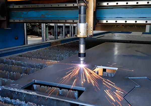
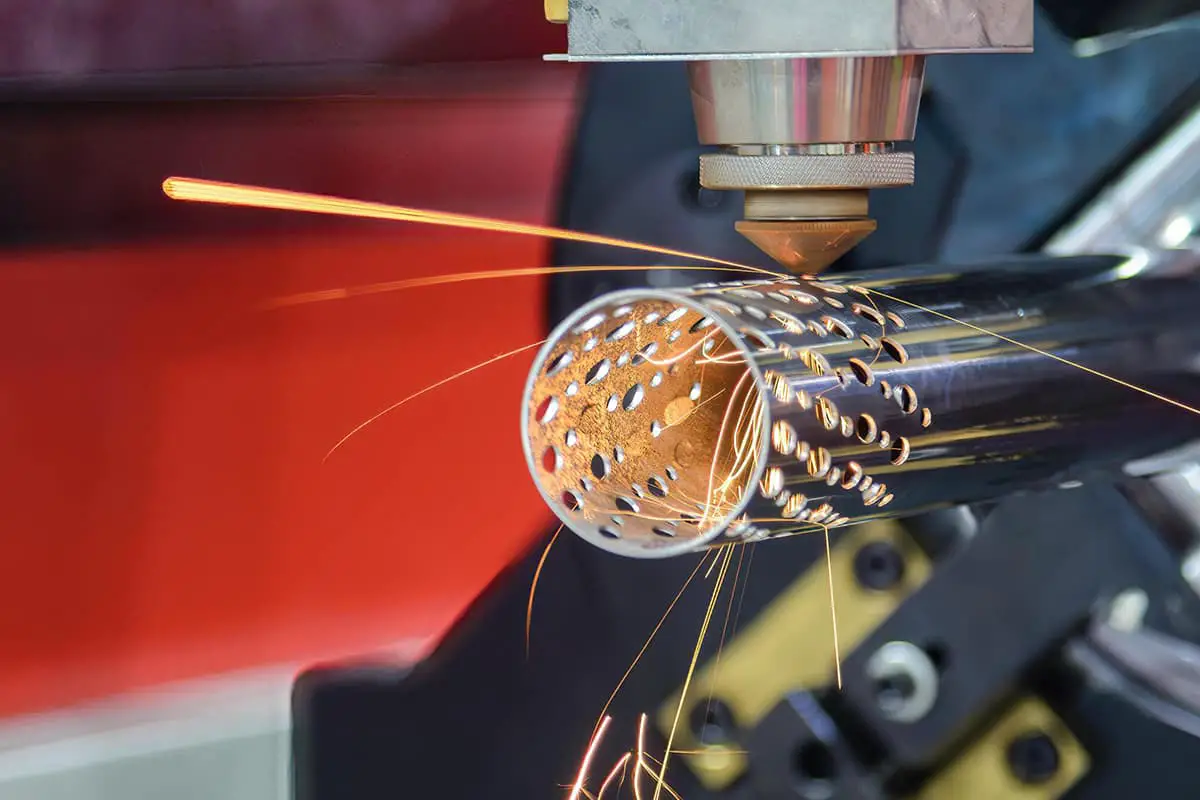
Plasma cutting machines come in various shapes and sizes. There are giant plasma cutting machines controlled by robot arms for precise cutting, as well as simplified handheld plasma cutting machines used in workshops.
Regardless of their size, all plasma cutting machines are based on the same principles and have similar structural designs.
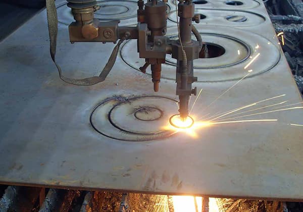
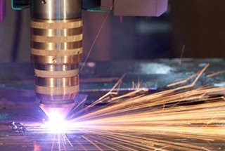
When a plasma cutting machine is in operation, compressed gases such as nitrogen, argon, or oxygen are delivered through a narrow channel. A negative electrode is placed in the middle of the channel. When power is supplied to the negative electrode and the nozzle is in contact with the metal, an electrically conductive circuit is formed, generating high-energy sparks between the electrode and the metal.
As the inert gas flows through the channel, the sparks heat up the gas until it reaches the fourth state of matter. This reaction produces a plasma stream with a temperature of up to about 16,649 degrees Celsius and a flow rate of up to 6,096 meters per second, quickly turning the metal into slag.
The plasma itself has a current flowing through it. As long as the electrode is continuously powered and the plasma is in contact with the metal, the arc cycle will be continuous.
To prevent oxidation and damage caused by unknown properties of the plasma, the plasma cutter nozzle is equipped with another set of channels that continuously release protective gas to protect the cutting area. The gas pressure of the protective gas can effectively control the radius of the columnar plasma.
Plasma Cutting
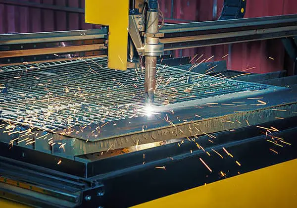
Plasma cutting machines have become a common tool in modern industry. They have been widely used in customized car workshops, as well as in the manufacturing of custom chassis and car bodies by car manufacturers.
Construction companies use plasma cutting machines in large-scale projects to cut and manufacture large beams and metal plates. Locksmiths can use plasma cutting machines to drill holes in secure areas when customers are locked out.
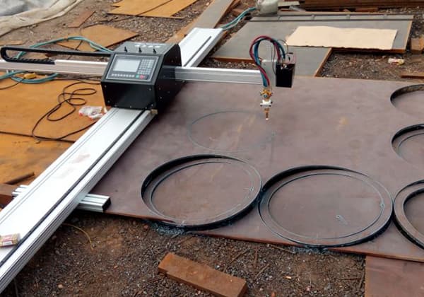
In a CNC (Computer Numerical Control) cutting system, you don’t need to touch the material. All you have to do is draw the shape you want to cut on the computer and the cutting process will be automated.
1. Working Principle
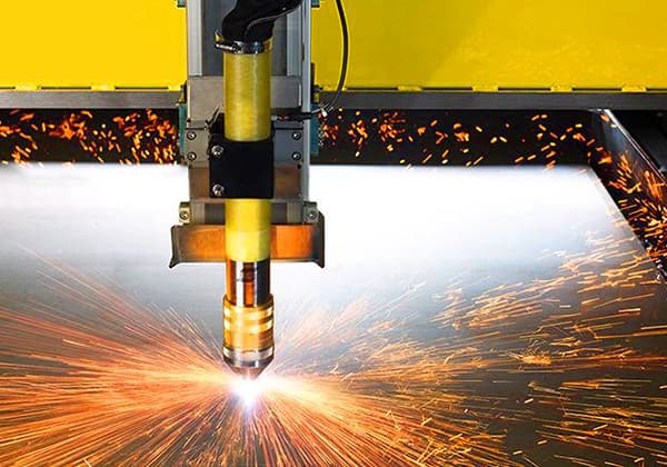
Plasma is a gas heated to extremely high temperatures and highly ionized. The arc power is transferred to the workpiece, which melts and is blown away, creating a working state of plasma arc cutting.
Compressed air enters the cutting torch and is distributed into two streams by the gas chamber, forming plasma gas and auxiliary gas. Plasma gas arc melts the metal, while the auxiliary gas cools the various parts of the cutting torch and blows away the melted metal.
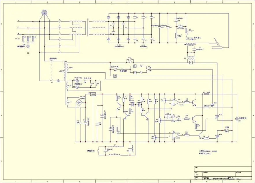
The cutting power supply includes a main circuit and a control circuit. The electrical principle block diagram is shown in the figure:
The main circuit consists of a contactor, a high-leakage resistance three-phase power transformer, a three-phase bridge rectifier, a high-frequency arc ignition coil, and protection elements. It features a steep external characteristic caused by the high-leakage resistance. The control circuit completes the entire cutting process through the button switch on the cutting torch:
Pre-gas supply – Main circuit power supply – High-frequency arc ignition – Cutting process – Arc stop – Stop.
The power supply of the main circuit is controlled by the contactor; the gas flow is controlled by the solenoid valve; and the high-frequency oscillator ignites the arc and stops working after the arc is established.
In addition, the control circuit also has the following internal lock functions:
Thermal control switch action, stop working.
2. Cutting Malfunctions
(1) Cut not through:
a: The thickness of the plate exceeds the equipment’s applicable range.
b: The cutting speed is too fast.
c: The inclination of the cutting torch is too large.
d: Compressed air pressure is too high or too low.
e: The mains voltage is too low.
(2) Plasma arc instability:
a: The cutting torch moves too slowly.
b: The power supply is supplied by two phases, and the operating voltage decreases.
c: Compressed air pressure is too high.
3. Installation, maintenance, and replacement of cutting torch parts
When installing or replacing cutting torch parts, disassemble them in the order of the protective cover-conductive nozzle-gas distributor-electrode-cutting torch body with the cutting torch head facing up, and assemble them in the reverse order.
When installing the nozzle, ensure that it is concentric with the electrode. The protective cover should be tightened, and the nozzle should be pressed tightly. If there is looseness, cutting cannot be performed.
Use the cutting torch reasonably. Contact the nozzle with the workpiece before arc ignition. When cutting is finished, release the handle button to stop the arc, and then move the cutting torch away from the workpiece surface to extend the service life of the parts. When the central hollow of the nozzle affects the cutting quality, it should be replaced in time.
When the center of the electrode is recessed more than 2 millimeters or cannot ignite the arc, the electrode can be installed in reverse or updated.
When the protective cover or gas distributor is cracked or severely damaged, it should be replaced in time.
When the insulation of the cutting torch body, synthetic leather jacket, insulation of the cable, or damage to the gas pipe is found, it should be repaired or replaced in time.
To remove the cutting torch, retract the synthetic leather jacket, disassemble the switch connection wires, retract the handle backward, and then disassemble the connection joints of the cutting torch body.
When replacing a new ceramic protective cover, apply a little Vaseline oil to the O-ring seal on the cutting torch body before screwing it in to extend the service life of the seal.
4. Common Faults and Troubleshooting Methods
No.
Faults
Causes
Solutions
1
Turn on the power switch, the power indicator light does not light up
1. The fuse in the power supply switch is broken
replace
2. The fuse behind the power box is broken
Check and replace
3. The control transformer is faulty
replace
4. The power switch is broken
replace
5. The indicator light is broken
replace
2
Unable to preset cutting gas pressure
1. The air source is not connected or there is no air in the air source
Connect the air source
2. The power switch is not in the “on” position
Trigger
3. The pressure reducing valve is damaged
Repair or replace
4. Poor wiring of the solenoid valve
Check wiring
5. The solenoid valve is faulty
replace
3
Pressing the cutting torch button during operation results in no airflow
1. Pipeline leakage
Fix the leaked part
2. The solenoid valve is faulty
replace
4
After the conductive nozzle contacts the workpiece, press the cutting torch button and the work indicator light will light up, but the arc cutting has not been triggered
1. KT1 is broken
replace
2. The high-frequency transformer is faulty
Check or replace
3. Spark rod surface oxidation or improper gap distance
Polishing or adjusting it
4. Short circuit of high-frequency capacitor C7
replace
5. The air pressure is too high
Lowering
6. The loss of the conductive nozzle is too short
replace
7. Rectifier bridge rectifier element open circuit or short circuit
Check and replace it
8. Poor contact or open circuit of the cutting torch cable
Repair or replace
9. The ground wire of the workpiece is not connected to the workpiece
Connected to workpiece
10. There is a thick paint layer or dirt on the surface of the workpiece
Clear and make conductive
5
The cutting indicator light does not light up when the conductive nozzle contacts the workpiece and the cutting torch button is pressed
1. Thermal control switch action
Wait for cooling or working again
2. The cutting torch button switch is damaged
replace
6
Control the fuse to break after high-frequency startup
1. High frequency transformer damaged
Check and replace
2. Control transformer damaged
Check and replace
3. Short circuit of contactor coil
replace
7
The fuse of the main power switch is broken
1. Rectifier element short circuit
Check and replace
2 Main transformer failure
Check and replace
3. Short circuit of contactor coil
Check and replace
8
High frequency occurrence but no arcing
1. The rectifier component is faulty (there is an abnormal sound inside the machine)
Check and replace
2. The main transformer is damaged
Check and replace
3. C1-C7 Down
Check and replace
9
Long term work interruption and arc failure
1. The temperature of the main transformer is too high, and the thermal control switch acts
Wait for cooling before working, pay attention to lowering
As the founder of MachineMFG, I have dedicated over a decade of my career to the metalworking industry. My extensive experience has allowed me to become an expert in the fields of sheet metal fabrication, machining, mechanical engineering, and machine tools for metals. I am constantly thinking, reading, and writing about these subjects, constantly striving to stay at the forefront of my field. Let my knowledge and expertise be an asset to your business.
Have you ever wondered how to achieve flawless cuts with CNC plasma machines? Mastering cutting parameters is the key. This article dives into the essential aspects like cutting current, speed,…
Have you ever wondered about the cutting-edge technology revolutionizing metal fabrication? Plasma cutting is a game-changer in the industry, offering unparalleled speed, precision, and versatility. In this article, we'll dive…
This article explores the fascinating world of metal heat cutting, from flame cutting to plasma and laser methods. Learn about their unique advantages, limitations, and the impact on modern manufacturing.…
Imagine being surrounded by a cloud of invisible, harmful particles every time you work. Plasma cutting, though efficient, produces hazardous dust and gases that can severely affect health and the…
Imagine slicing through metal like a knife through butter, but on-the-go. Portable plasma cutters are revolutionizing industries from automotive to aerospace by offering precise, high-speed cutting capabilities at a fraction…
Imagine effortlessly slicing through thick sheets of metal with precision and speed. This article delves into the operational intricacies of a CNC plasma cutting machine, guiding you through everything from…
Have you ever wondered how manufacturers achieve precision and efficiency when cutting stainless steel? This article dives into six advanced techniques for stainless steel cutting, highlighting their benefits and applications.…