There are many established basic rules in mechanical drafting, and specifically, the ASME Y14.5-2009 sets forth sixteen essential rules.
These rules must be thoroughly understood and applied in drafting, interpreting, or reviewing technical drawings. Let’s delve into each of these sixteen rules one by one.
Rule 1: All dimensions, with the exception of reference dimensions, maximum and minimum dimensions, or raw materials, must have tolerances.
Reference dimensions typically don’t have tolerances. Why is this? It’s because reference dimensions are usually repetitive dimensions or closed dimensions on drawings, which are used purely for reference information. Reference dimensions neither guide production nor inspection, so when you see a reference dimension on a drawing, you can disregard it.
On drawings, we often see the notation of MAX (maximum) or MIN (minimum). Do these dimensions have tolerances? The answer is yes. For MAX dimensions, the lower limit of its tolerance is zero, and for MIN dimensions, its upper limit of tolerance is infinite.
Therefore, when specifying MAX or MIN dimensions, we must fully consider whether there is an impact on function at the limit deviation. For example, if we mark a fillet as R1 MAX, then we must consider whether the absence of a fillet (i.e., when it’s zero) will affect the function. If so, an appropriate lower limit tolerance must be specified.
There are also many theoretical dimensions (i.e., basic dimensions) on drawings. Do they have tolerances? Theoretical dimensions are defined as numerically correct sizes, shapes, profiles, directions, or positions used to define a body or a target datum.
When this theoretical dimension is used to define the size, shape, profile, direction, or position of a body, its tolerance is defined by the corresponding form and position tolerance of the body. When this theoretical dimension is used to define the size, shape, or position of a target datum, its tolerance should be determined according to ASME Y14.43 gauge and fixture tolerance guidelines. Therefore, theoretical dimensions also have tolerances.
The methods of indicating dimensional tolerances on drawings are as follows:
· Directly annotating dimension limits or tolerance values on the dimension itself.
· Indicating in the form of geometric dimensional tolerances.
· Defining tolerances for specified dimensions in notes or tables.
· Defining tolerances for specific forms or processes in other referenced documents in the drawing.
· Defining tolerances for all dimensions without specified tolerances in the general tolerance column.
Rule 2: Dimensions and tolerances must be fully defined to fully understand all characteristics of each form.
A form’s characteristics include size, shape, direction, and position. It’s necessary to define the size and tolerance of all characteristics of each form on the drawing. Sizes and tolerance values can be expressed through engineering drawings or defined by CAD product definition databases. Guessing or determining dimensions by measuring the drawing is not permitted.
Rule 3: Only indicate all necessary dimensions used to describe the product.
The meaning of all necessary dimensions is that the dimensions on the drawing should be just right, not too many or too few, to fully express all the characteristics of all forms. There should be no superfluous dimensions on the drawing, such as closed dimensions.
As previously discussed, we can ignore any reference dimension, so the drawing should minimize the use of reference dimensions. Reference dimensions, besides adding a sense of disorder to the drawing, serve no purpose at all.
Rule 4: Dimensions should be chosen based on the product’s function and fit, and should not be open to multiple interpretations.
This emphasizes that the dimensions and tolerances we define during design should be based on meeting the functional and fit requirements of the product. The design process should consider manufacturability and inspectability, but not at the expense of functional requirements.
Rule 5: Product designs should not specify manufacturing methods
Product designs should only indicate dimensions and performance requirements necessary for the functionality of the product. How it is manufactured falls under the purview of the manufacturing engineers.
As designers, we should provide ample freedom to the manufacturing team. Our consideration should be to provide the widest possible tolerance range that meets the product’s functionality, enabling sufficient manufacturing capability, rather than specifying the method of manufacturing. For instance, for a hole, we should only mark the diameter, without specifying whether it is drilled, punched, milled, turned, ground, or made through other processes.
As long as the final product satisfies the diameter tolerance, the manufacturing process doesn’t matter. However, when the manufacturing process is an inseparable part of the product’s features, it should be specified in the design or reference documents. For example, if the functionality requires the hole to be free of spiral machining marks while meeting diameter tolerance, the design can specify that the hole needs to be ground.
Rule 6: While providing final product dimensions, it’s acceptable to mark non-mandatory process parameters like machining allowances
Usually, process parameters aren’t required to be marked on designs, but if they are, it must be clearly stated that they are non-mandatory. As previously mentioned, this falls within the realm of manufacturing engineers, and they should be given ample freedom.
Rule 7: Dimensions should be arranged logically for optimal readability. They should be placed on the actual outline and marked on visible contour lines
This is a basic requirement for drafting, which we won’t expand on here.
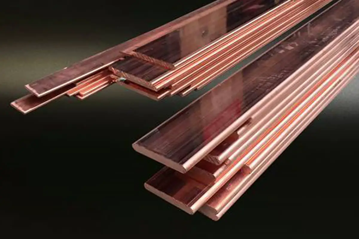
Rule 8: Raw materials, such as wire, pipe, sheet, rod, or other materials produced by measurement or brand number, should be marked with linear dimensions like diameter or thickness.
The measurement or product brand number should be marked in parentheses following the dimension
This rule is specific to raw materials, each of which has its own standard for notation.
Rule 9: Centerlines and contours shown as right angles on the design without markings are assumed to be 90 degrees
There are many relationships in designs that are assumed to be 90 degrees. These assumed 90-degree tolerances should be controlled as unmarked angle tolerances.
Rule 10: The centerlines or surfaces of arrayed bodies defined or positioned by basic dimensions, if shown as right angles on the design without markings, are assumed to be basic 90-degree dimensions
Arrayed bodies refer to a group (two or more) of bodies with the same shape and size distributed in a regular pattern. When the centers of these bodies are defined or positioned by basic dimensions, the assumed 90-degree basic angle tolerance is controlled by the corresponding form and position tolerance.
Rule 11: When the center axis line, center plane, or surface is consistently displayed in the diagram, it’s assumed to be a basic dimension with a value of zero, and their relationship is defined by the form and position tolerances.
This is common knowledge. The tolerances of these basic dimensions, which are assumed to be zero, should be controlled by the corresponding form and position tolerances. If the form and position tolerances aren’t specified, they should be controlled by the unspecified form and position tolerances in the general technical requirements column.
Rule 12: Unless otherwise specified, all dimensions refer to room temperature of 20°C (68°F). If measurements are taken at other temperatures, compensation for the dimensions should be considered.
Note that the room temperature here is 20 degrees, not 23 or 25 degrees. Therefore, we require all measuring rooms to control the temperature at 20 degrees to ensure that the testing results accurately reflect whether the product requirements are met.
If it’s impossible to measure at room temperature of 20 degrees, we should consider compensating for the temperature effects on the measurement results, especially for parts with high temperature sensitivity.
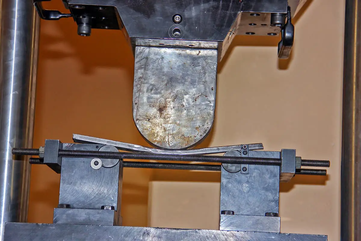
Rule 13: Unless otherwise specified, all dimensions and tolerances apply to the free state condition.
All dimensions marked on the drawing refer to the dimensions of the parts in a stress-free state. For some non-rigid parts, we can mark the dimensions after the parts are constrained according to regulations, and the method of constraining the parts must be marked on the drawing.
If we want to mark some dimensions of the parts in their free state, we must mark them with the free state symbol F.
Rule 14: Unless otherwise specified, all geometric dimensional tolerances apply to the entire length, width, or depth of the form.
I believe everyone is familiar with this. What I want to remind you is that due to the application of the inclusive principle, the length, width, or depth of the form greatly affects the control of the form’s shape.
For a 3mm long round bar and a 30mm long round bar, the maximum straightness allowed under the same diameter tolerance is the same, but the actual bending situation is vastly different.
Rule 15: All dimensions and tolerances only apply to the product level described in the drawing. The dimensional tolerance of a form described at one drawing level (such as a part diagram) does not necessarily apply to the dimensional tolerance of that form at other drawing levels (such as assembly diagrams).
That is to say, the size on a part diagram may not necessarily apply to the assembly diagram. For example, if we weld a bracket with an opening of 10 +/- 0.5 to a platform, due to the deformation of welding, the holding of the welding fixture, and other factors, it’s difficult to meet the size requirement of 10 +/- 0.5 on the welded piece.
That is, this size is no longer applicable to the welded piece drawing. Therefore, we cannot require the size of the same form on the assembly drawing based on the size on a part drawing. If it’s necessary to control this form on the assembly drawing, the size must be marked on the assembly drawing.
Rule 16: Unless otherwise specified, when a coordinate system appears on the drawing, it must be right-handed. Each coordinate axis must be marked and the positive direction indicated.
This point is rarely used, so no further detailed explanation is necessary, just follow it.
Above is an introduction to the 16 basic drawing guidelines stipulated by the ASME standard.