1. Dimensioning of part drawings
1. Rationality of part dimensions
2. Methods and steps for dimensioning parts
3. Precautions for dimensioning
Basic requirements for dimensioning in part drawings
The dimensions in the part drawing shall be marked in accordance with the standard, complete, clear and reasonable.
Requirements for reasonable dimensioning:
(1) Meet the design requirements to ensure the quality of the machine,
(2) Meet the process requirements to facilitate structural manufacturing and inspection.
To meet these requirements, we must master certain practical production knowledge and relevant professional knowledge.
1. Rationality of part dimensions
The dimensions in the part drawing shall not only meet the requirements of correctness, integrity and clarity, but also make the dimensions reasonable.
Definition of rationality of dimensions on part drawing:
- Meet the design requirements and ensure the service performance of components;
- Meet the requirements of processing technology and make processing and measurement convenient;
- Low cost.
Whether the dimensions are reasonable or not, the key points are as follows:
- Distinguish the primary and secondary dimensions of parts;
- Select appropriate dimensional tolerance;
- Select the dimension datum correctly.
1. Main and non main dimensions
Main dimensions:
Dimensions that affect the specification and performance of components or machines, such as mating dimensions, dimensions to determine the exact position of parts in components, connection dimensions, installation dimensions, and dimensions that affect the interchangeability and working accuracy of parts.
Non main dimensions:
Such as external outline dimension, non fit dimension, dimension used to meet the mechanical properties, structural shape and process requirements of parts, etc.
Main dimensions shall be directly indicated:
2. Dimension datum of parts
Datum: select a group of geometric elements on the part as the basis for determining the mutual position relationship of other geometric elements.
According to different purposes, the benchmark is divided into design benchmark and process benchmark.
Design datum: the datum used to determine the exact position of the part in the assembly. Usually, one of them is selected as the main dimension datum.
Process benchmark: the benchmark for processing and measurement, which is often used as the auxiliary dimension benchmark.
Elements often used as datum: important bottom surface, end face, symmetrical plane, assembly joint surface, axis of main hole or shaft, etc.
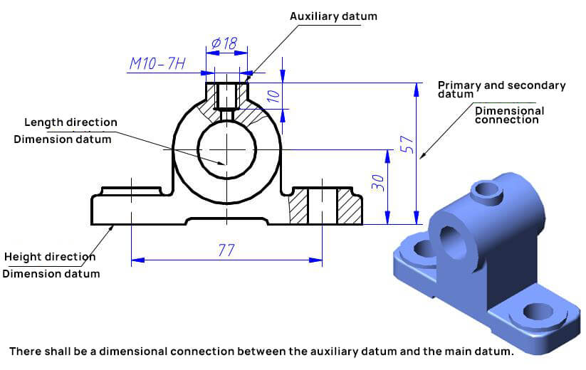
Dimension datum selection:
There shall be a dimensional connection between the auxiliary datum and the main datum.
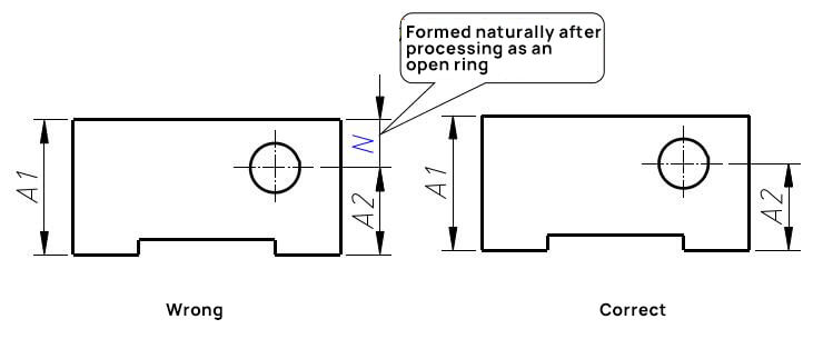
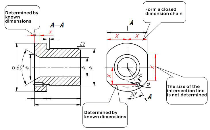
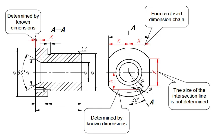
3. Closed dimension chain
The dimensions of parts in the same direction can be connected end to end and listed in the form of dimension chain.
However, it should be avoided to form a closed dimension chain.
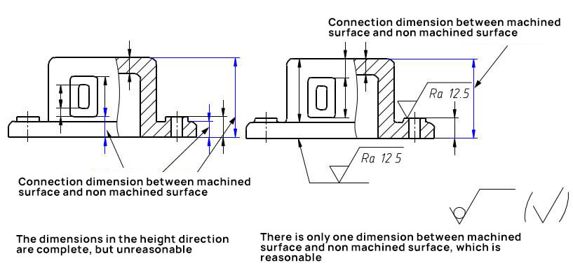
4. Only one non machined surface can be connected with the machined surface in the same direction.
The blank size and processing size shall be marked separately as far as possible to facilitate drawing reading.
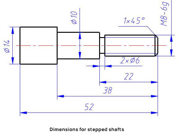
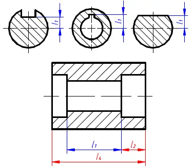
5. Mark the dimensions according to the processing sequence
Dimensions for stepped shafts
Processing sequence
- 1. Blanking;
- 2. Turning φ 10 long 38 shaft section;
- 3. Turning φ 8 long 22 shaft section, turning and retracting the cutter slot;
- 4. Thread turning and chamfering.
2. Methods and steps for dimensioning parts
General methods and steps:
(1) Analyze the function of part structure shape and understand the combination relationship with adjacent parts;
(2) Distinguish the primary and secondary dimensions, determine the design basis and mark the main dimensions;
(3) Select the process benchmark and note all non main dimensions with shape analysis method.
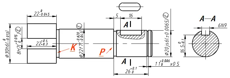
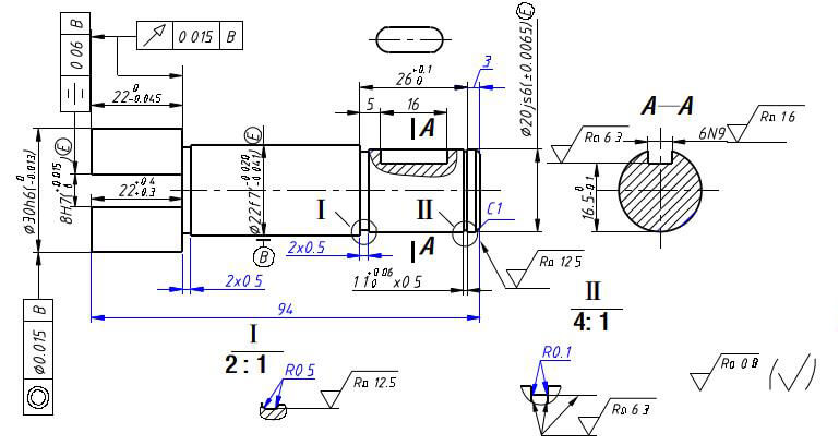
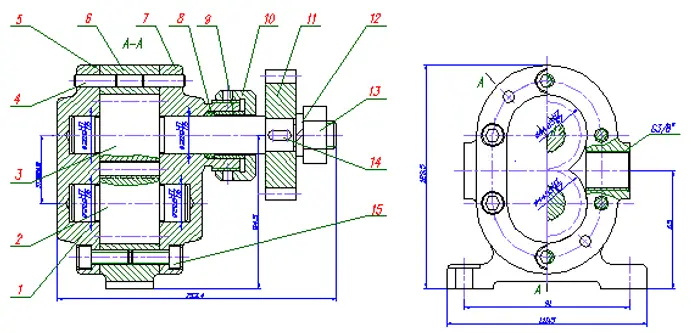
Example: vane pump shaft
(2) Mark the main dimensions and their deviations from the design basis.
- Radial dimension;
- Axial dimension;
- Keyway size
(3) Considering the processing and manufacturing requirements, select the appropriate process benchmark, note all other dimensions, select the left and right end faces of the shaft as the process benchmark, and mark other dimensions.
Mark the surface structure requirements, geometric tolerance and other technical requirements.
(4) Check
Whether the main dimensions and design basis are appropriate, whether there are omissions, whether the dimension value and its deviation meet the design requirements, and whether they are coordinated with the relevant dimensions on the part drawing of relevant parts.
Check whether the dimensions are complete.
Check whether the setting size and positioning size are complete according to the structural shape of the parts.
Check whether it meets the national standard.
3. Precautions for dimensioning
1. Earnestly implement national standards.
There are standard values for length, diameter, angle, taper and its deviation, which should be selected generally;
Standard structural elements (gear teeth, threads, etc.) shall be marked with dimensions and deviations according to regulations.
2. The dimensions shall be complete, but there shall be no redundant dimensions.
3. In order to facilitate the reading of drawings, the dimensions required for the same type of work shall be marked centrally, such as the dimensions of keyway on shaft.
4. The size of the contact shall be consistent.
Each part in the component has the relationship of fit, connection, transmission, position, etc. When marking the size of their connection, the dimension datum, marking content and marking form shall be coordinated as far as possible.
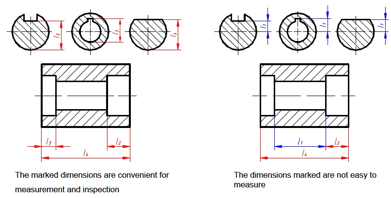
5. Consider the requirements of convenient measurement and inspection.
The marked dimensions are convenient for measurement and inspection
The dimensions marked are not easy to measure
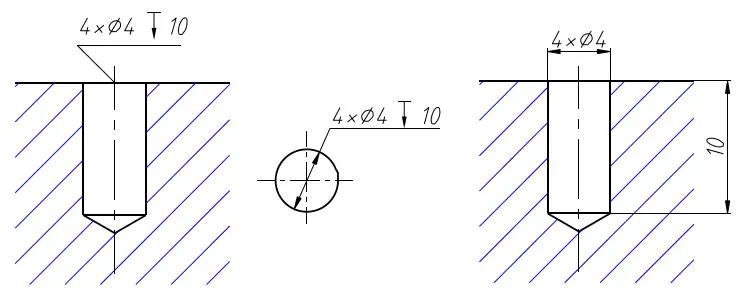
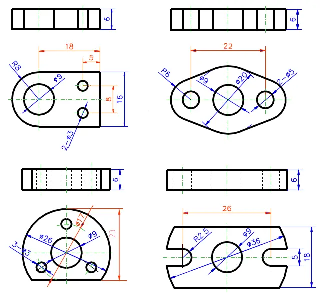
4. Dimension annotation of various small holes on parts
(1) Light hole
Simplified injection method Ordinary note method
Simplified injection method Ordinary note method
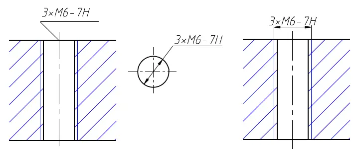
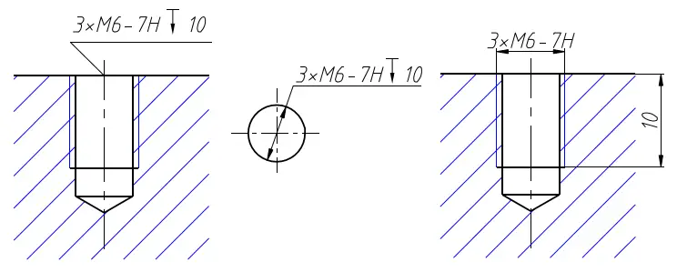
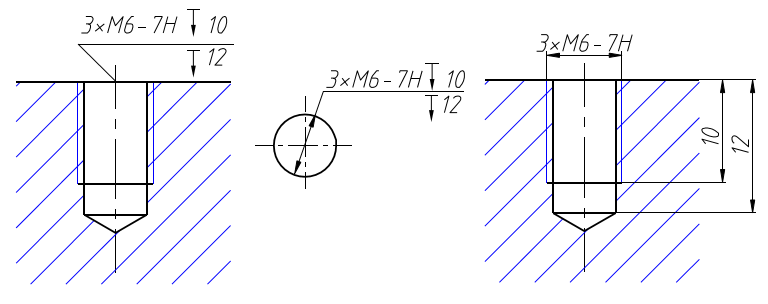
(2) Screw hole
Simplified injection method Ordinary note method
Simplified injection method Ordinary note method
Simplified injection method Ordinary note method
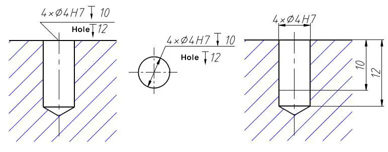
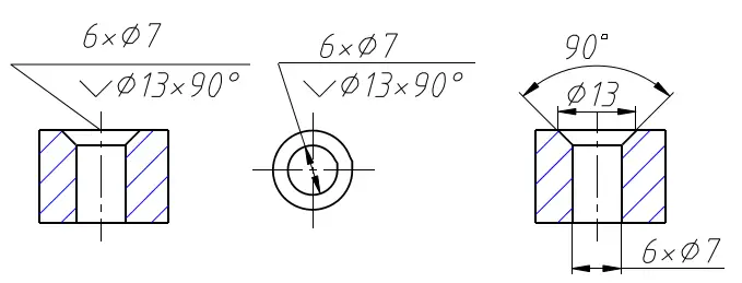
(3) Counterbore
Simplified injection method Ordinary note method
Simplified injection method Ordinary note method
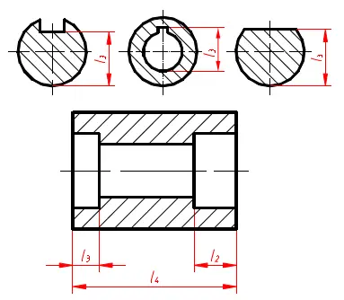
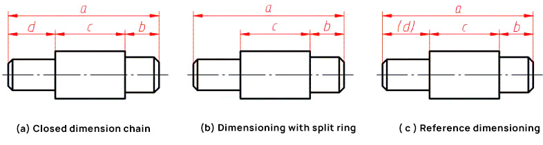
Generally, the size should be marked as an opening, that is, there should be no redundant size.
At this time, the ring with the lowest accuracy requirement is not marked with size, which is called an opening ring.
In some cases, in order to avoid addition and subtraction during processing, the dimension of the split ring is marked with brackets, which is called “reference dimension“.
Generally, the reference dimension is not inspected in production.
2. Dimension annotation method of assembly
1. Basic requirements for dimensioning of assembly
2. Dimension classification and dimension datum
3. Basic shape dimension annotation method
4. Overall dimension annotation
5. Dimension marking of cutting body and intersecting body
6. Problems needing attention in dimensioning
7. Examples of dimensioning
1. Basic requirements for dimensioning of assembly
1. The dimensions shall be complete, and the shape and size of the object shall be completely determined without omission or repetition.
2. The dimensions shall comply with the provisions of national standards, that is, strictly abide by national standards
3. The dimensions shall be reasonable and the arrangement shall be clear.
2. Dimension classification and dimension datum
1. Dimension datum
The starting point of dimensioning is the dimension datum.
2. Setting size
Determine the size of the shape and size of each component of the assembly.
3. Positioning dimension
Determine the relative position and size between the basic shapes.
4. Overall dimensions
Total length, total width and total height of each body.
1). Dimension datum
2). Setting size
3). Positioning dimension
4). Overall dimensions
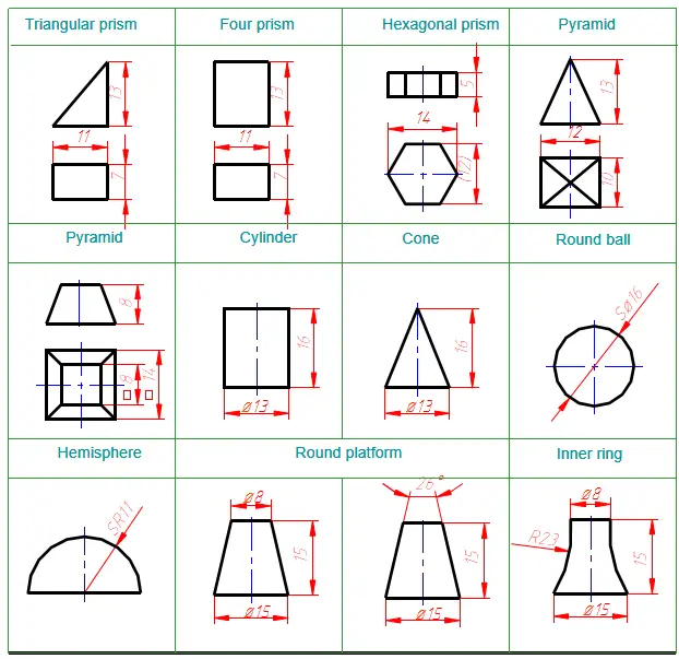
3. Basic shape dimension annotation method
4. Overall dimensions
Legend to dimension the overall dimension
Legend without direct overall dimension
5. Dimension marking of cutting body and intersecting body
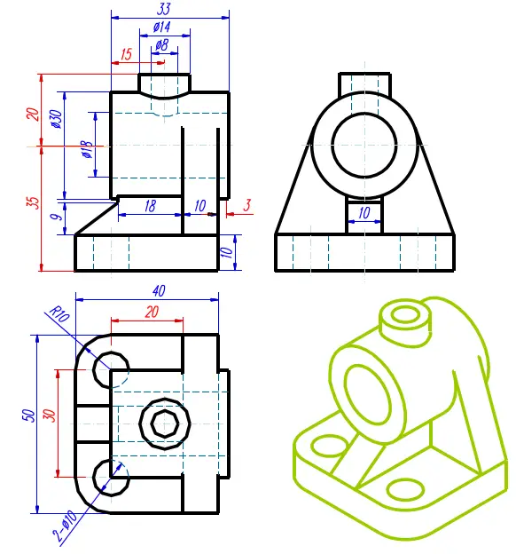
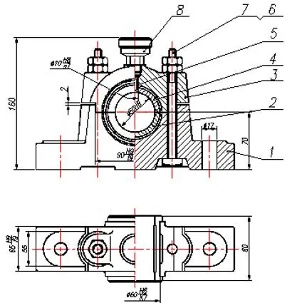
6. Examples of dimensioning
Steps to dimensioning:
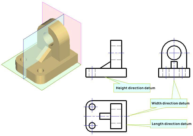
1. Conduct shape analysis. The assembly can be divided into five basic parts: bottom plate, cylinder, support plate, rib plate and small cylinder.
2. Mark the fixed size of the shape one by one.
3. Select the dimension datum, select the bottom surface of the bottom plate as the datum in the height direction, select the symmetrical plane passing through the cylinder axis as the dimension datum in the length direction, and select the rear end face of the cylinder as the dimension datum in the width direction.
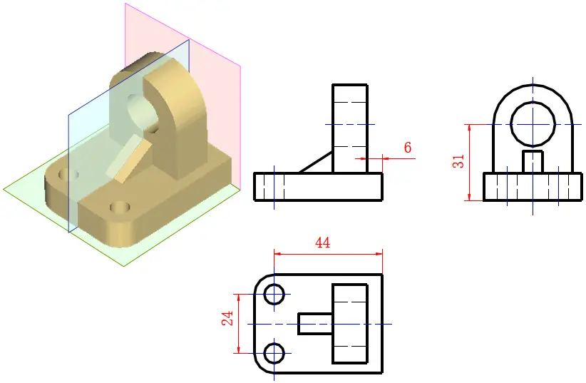
4. Mark the positioning dimension.
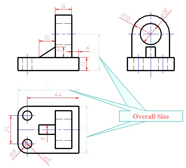
5. Adjust and mark the overall dimension.
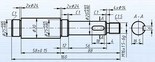
Shaft parts shall conform to the processing sequence and inspection method
Machining sequence of shaft:
- Blanking, turning Φ30, length 160
- Turning Φ25, length 88
- Turning Φ20, length 12
- Turning Φ16, leave length 56
- Turning undercut and chamfer
- Turning thread
- Turn around, turning Φ25, leave 58
- Turning undercut and chamfer
- Machining keyway
3. Precautions for dimensioning
The dimensions shall be complete, but there shall be no redundant dimensions.
Consider the requirements of convenient measurement and inspection.
The marked dimensions are convenient for measurement and inspection.
It is not necessary to note all dimensions of parts on the assembly drawing.
It is only necessary to further describe the performance, working principle, assembly relationship and required dimensions of the machine.
1. Specifications and dimensions
Also known as performance dimension, it reflects the specifications and working performance of components or machines.
This dimension should be determined first in the design. It is the basis for designing, understanding and selecting machines.
2. Assembly dimensions
The dimensions indicating the assembly relationship and working accuracy between parts generally include the following:
1. Fitting dimensions refer to some important dimensions with fitting requirements between parts.
2. Relative position dimension indicates the important distance and clearance between parts to be ensured during assembly.
3. Machining dimensions during assembly. Some parts can be machined only after they are assembled together. The machining dimensions during assembly shall be marked on the assembly drawing.
3. Installation dimension
The dimensions that need to be determined to install the components on the machine or the machine on the foundation.
4. Overall dimension
Indicates the total length, width and height of the machine or part.
It enables the required dimensions for packaging, transportation, installation and plant design.
5. Other important dimensions
It does not belong to the above dimensions, but the dimension should be guaranteed during design or assembly.