Sheet Metal Joining Process: The Ultimate Guide
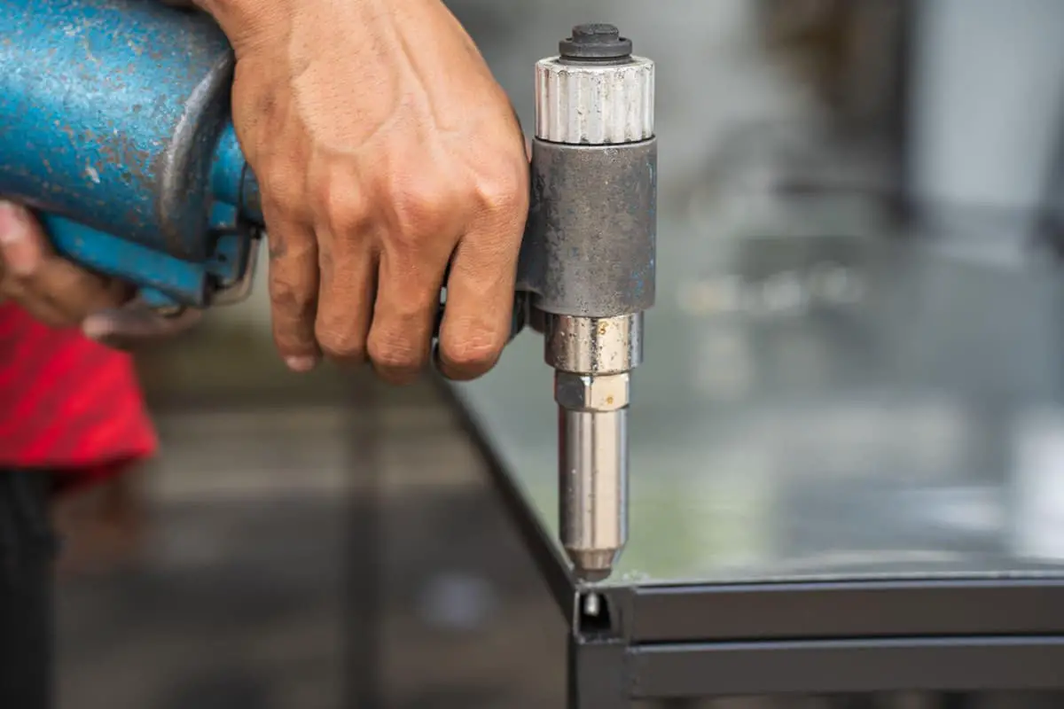
Have you ever wondered how sheet metal parts are joined together to create complex structures? In this blog post, we'll explore the fascinating world of sheet metal joining techniques. As…
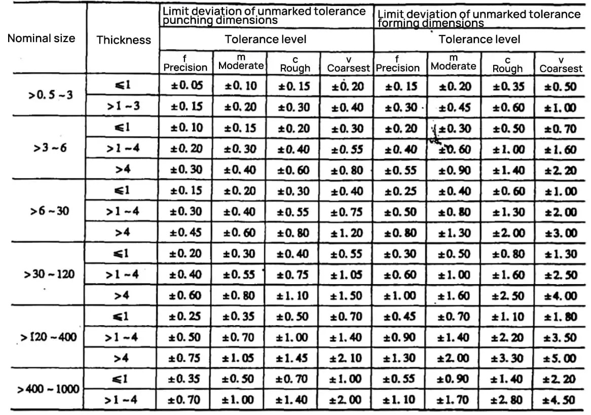
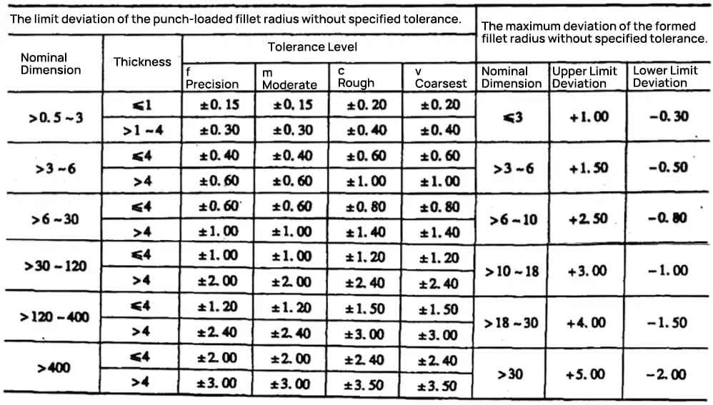
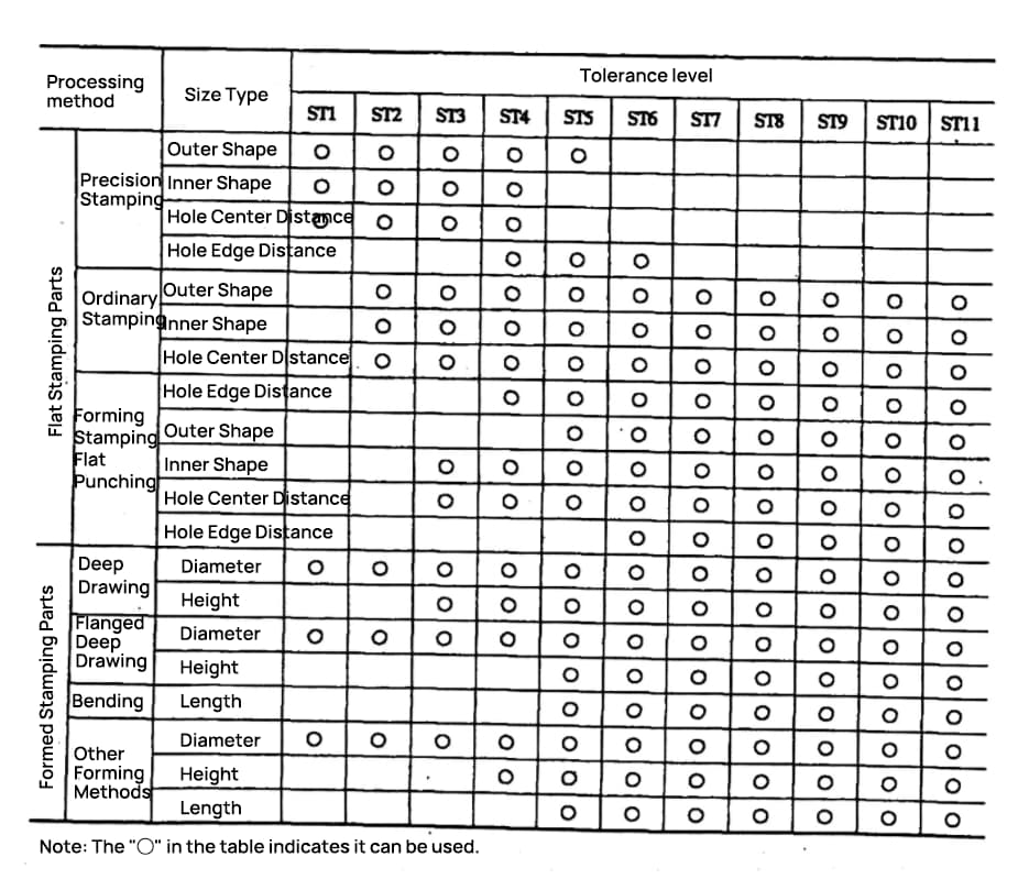
Have you ever wondered how precise engineering in sheet metal fabrication is achieved? Understanding sheet metal tolerances is crucial for ensuring that parts fit together perfectly in any mechanical project. This article will explore the different types of tolerances used in flat and formed stamping parts, from dimensional deviations to angular tolerances. By the end, you’ll grasp the importance of these tolerances and how they impact the quality and functionality of your metalworking projects. Dive in to learn the key factors that contribute to achieving precision in sheet metal fabrication.
Unit: mm
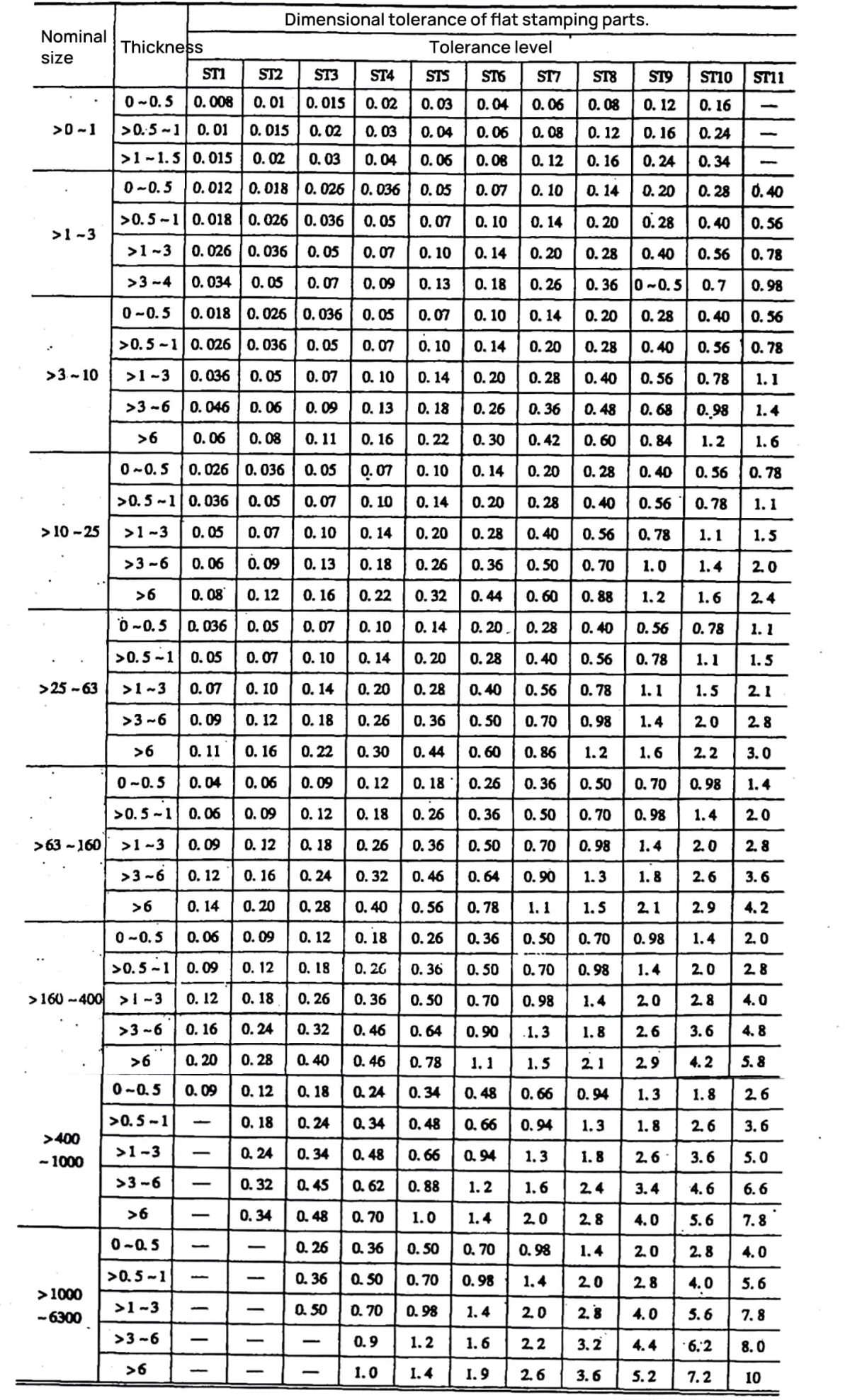
Unit: mm
Note:
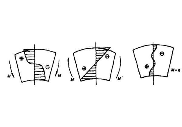
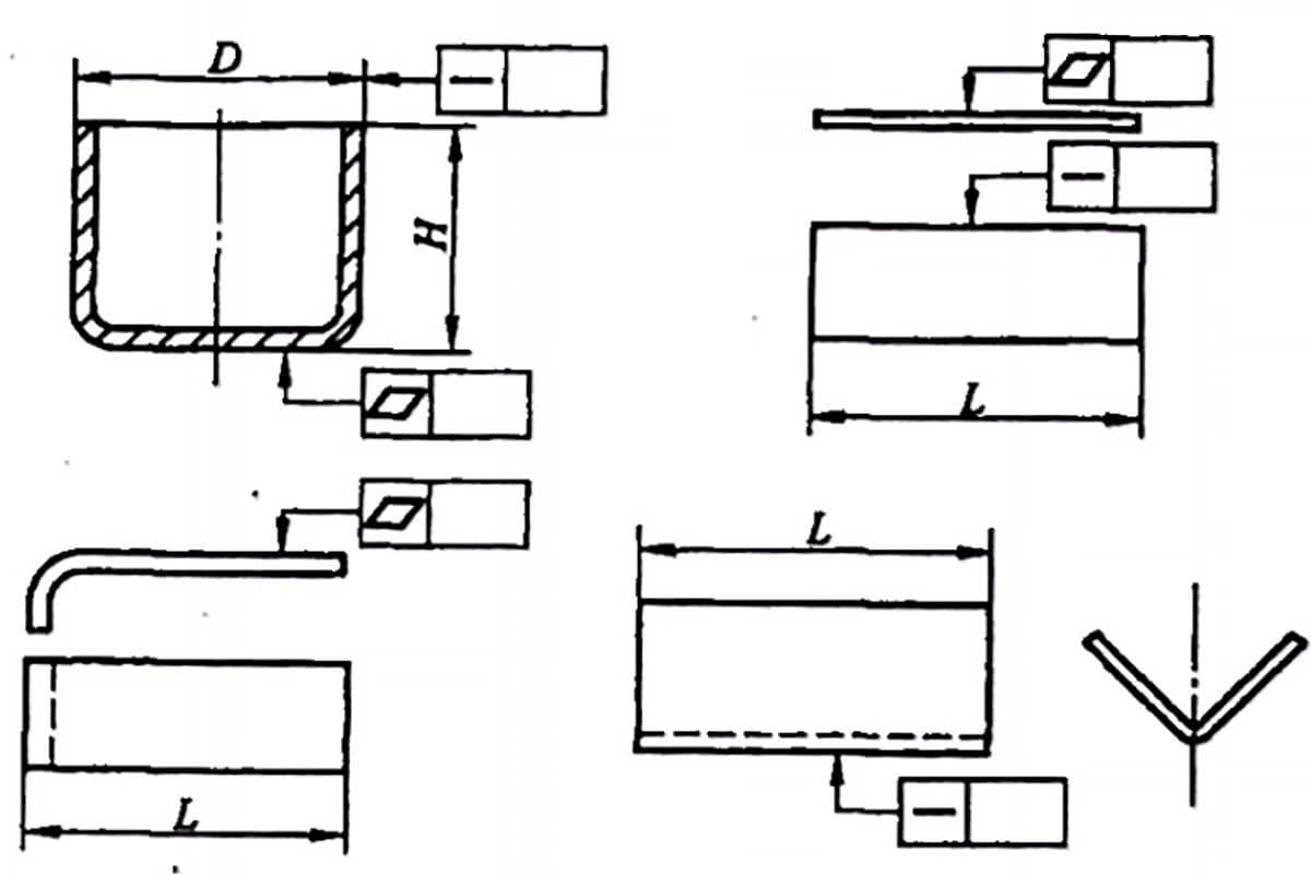
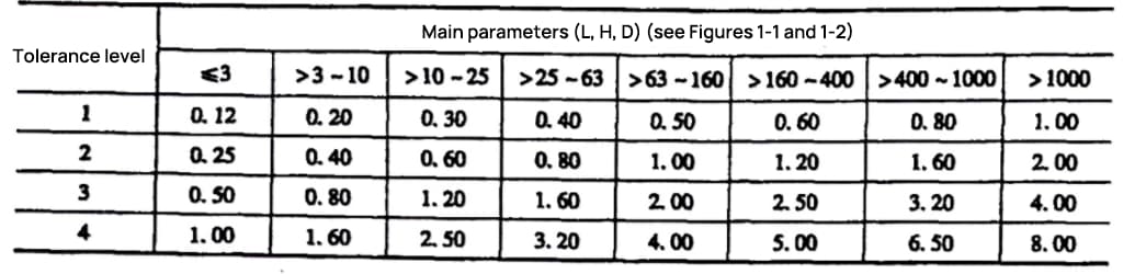
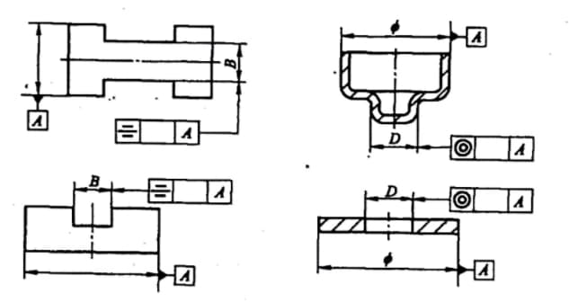
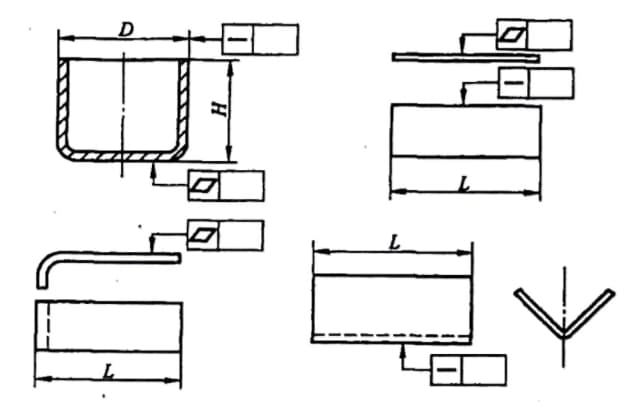
Coaxiality, symmetry, and primary parameters (L, H, D) are indicated in firgure below.
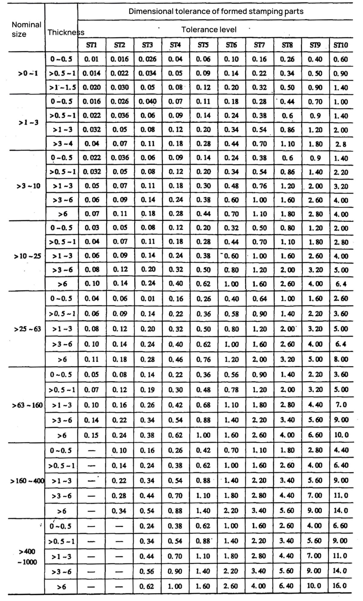
Unit: mm
Unit: mm
Note:
Unit: mm
Unit: mm
Note:
Unit: mm
Unit: mm
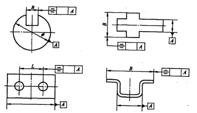
The primary parameters (L, H, D) for flatness and straightness are indicated as shown in Figures 1-3.
Unit: mm


As the founder of MachineMFG, I have dedicated over a decade of my career to the metalworking industry. My extensive experience has allowed me to become an expert in the fields of sheet metal fabrication, machining, mechanical engineering, and machine tools for metals. I am constantly thinking, reading, and writing about these subjects, constantly striving to stay at the forefront of my field. Let my knowledge and expertise be an asset to your business.