Imagine transforming the design and manufacturing of sheet metal parts from a cumbersome, error-prone process into a seamless, efficient operation. This article delves into the powerful role of CAD/CAM technology in revolutionizing sheet metal fabrication. By integrating computer-aided design and manufacturing, companies can ensure precise designs, streamline production, and significantly reduce costs. Discover how leveraging CAD/CAM can enhance product quality, optimize manufacturing processes, and maintain a competitive edge in today’s fast-paced industrial landscape.
The traditional product manufacturing process typically follows a design-first, manufacture-later sequence. Sometimes, the resulting product might face crucial issues during manufacturing and assembly, such as manufacturing difficulties, assembly interference, or worse, an inability to manufacture and produce.
This is often due to a lack of familiarity with the manufacturing process on the designer’s part or poor communication between the designer and other technical personnel. As industry data shows, product design accounts for 5% of the product cost, but it determines 75% of the total manufacturing cost and 80% of the product quality and performance.
Thus, to improve the processability of products, ensure the quality and performance, reduce production costs, and shorten the prototype cycle, it is crucial to use Computer Aided Design and Manufacturing (CAD/CAM) during product design, facilitating extensive information connection and feedback between design and manufacturing.
With this information linkage and feedback, designers can timely improve their designs, ensuring successful product design, process design, and manufacturing at once.
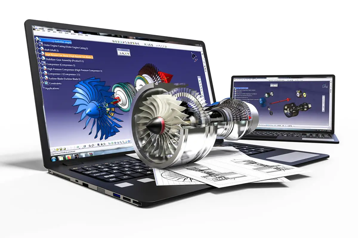
CAD/CAM involves the use of computers to generate and apply various digital information for product design and manufacturing. It is characterized by high intelligence, knowledge intensity, rapid updating, strong integration, and high efficiency. Its processing capacity continues to increase with the advancement of computer hardware and software technology.
CAD/CAM is commonly used in mechanical, electronic, textile, aviation, shipbuilding, and other industries for overall design, modeling, structural design, optimized design, simulation design of mechanism movement, pre and post-processing of finite element analysis, product quality characteristic computation, process design, numerical control processing, and more.
1.1 Computer Aided Design (CAD)
Computer Aided Design (CAD) involves using computer software to create and simulate the shape, structure, color, texture, and other features of newly developed products. As this technology continues to evolve, CAD is extensively used in various fields such as graphic printing and publishing.
The application range of CAD is broad, including architectural design drawing, mechanical drawing, circuit diagrams, and various other design methods.
Initially, CAD was primarily used in large companies in the automotive manufacturing, aerospace, and electronics industry. However, with the continuous decrease in computer manufacturing costs, its application range has expanded significantly.
Previously, drawing software was limited to flat design and lacked realism. With the ongoing development of computer technology, increased efficiency, and lower market prices, many companies have adopted three-dimensional drawing designs, making design blueprints much more intuitive.
1.2 Computer Aided Engineering (CAE)
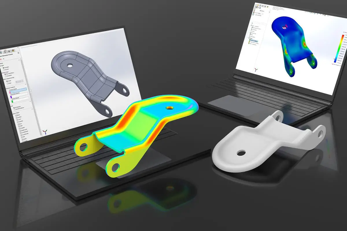
Computer Aided Engineering (CAE) is a numerical approximation method used to solve complex engineering and product structural strength, stiffness, buckling stability, dynamic response, heat conduction, three-dimensional multi-body contact, elasto-plasticity, and other analytical calculations, as well as structural performance optimization design issues.
The basic idea of CAE is to divide the solution area of a complexly shaped continuum into finite simple subregions, i.e., simplifying a continuum into an equivalent composite body composed of finite elements. By discretizing the continuum, the problem of solving field variables (stress, displacement, pressure, temperature, etc.) in the continuum is simplified to solving the field variable values on the finite element nodes.
The basic equations to be solved at this time are a set of algebraic equations, not the original differential equations that describe the real field variables of the continuum. The obtained solutions are approximate numerical solutions, and the degree of approximation depends on the type and number of elements used and the interpolation function of the elements.
CAE software can be divided into two categories:
1. Dedicated CAE software developed for specific types of engineering or products, used for product performance analysis, prediction, and optimization.
2. General-purpose CAE software that can analyze, simulate, predict, evaluate, and optimize the physical and mechanical properties of various types of engineering and products to achieve product technological innovation. The main body of CAE software is Finite Element Analysis (FEA) software.
The role of CAE in computer-aided design and manufacturing mainly manifests in the following aspects:
1. Enhancing design capabilities, ensuring the rationality of product design, and reducing design costs through computer analysis and calculation.
2. Shortening the design and analysis cycle.
3. The role of “virtual prototypes” played by CAE analysis largely replaces the resource-consuming “physical prototype validation design” process in traditional design. The role of “virtual prototypes” can predict product reliability throughout its lifecycle.
4. Using optimal design to find the best product design solution, reducing material consumption and costs.
5. Discover potential problems before product manufacturing or engineering construction.
6. Simulate various test schemes, reducing test time and expenses.
7. Conduct mechanical accident analysis to find the cause of accidents.
1.3 Computer Aided Process Planning (CAPP)
Computer Aided Process Planning, abbreviated as CAPP, refers to the use of computer hardware and software technology and environment to develop machining processes for parts through numerical calculations, logical judgments, and reasoning. With the help of a CAPP system, issues such as low efficiency of manual process design, poor consistency, unstable quality, and difficulty in optimization can be resolved.
CAPP is a technology that converts enterprise product design data into product manufacturing data. Through this computer technology, process designers are assisted to complete designs from raw materials to finished products. CAPP serves as a bridge connecting design and production in enterprise informatization construction, and also provides relevant data for the enterprise’s management department, acting as an intermediate link in enterprise information exchange.
The purpose of CAPP is to use computers to develop machining processes for parts, processing raw materials into parts required by engineering drawings. This is achieved by inputting geometric information (shape, size, etc.) and process information (materials, heat treatment, batch, etc.) of the parts to be processed into the computer, which then automatically outputs the process route and operation content of the parts.
1.4 Computer Aided Manufacturing (CAM)
Computer Aided Manufacturing, abbreviated as CAM, is the process of using computers for production equipment management, control, and operation. The input information is the process route and operation content of the parts, and the output information is the motion trajectory of the tool during processing (tool position file) and the numerical control program.
The core of computer-aided manufacturing is computer numerical control (CNC), which is the application of computers in the manufacturing process.
Computer-aided manufacturing systems generally have data conversion and process automation functions, and their scope includes computer numerical control and computer-aided process design.
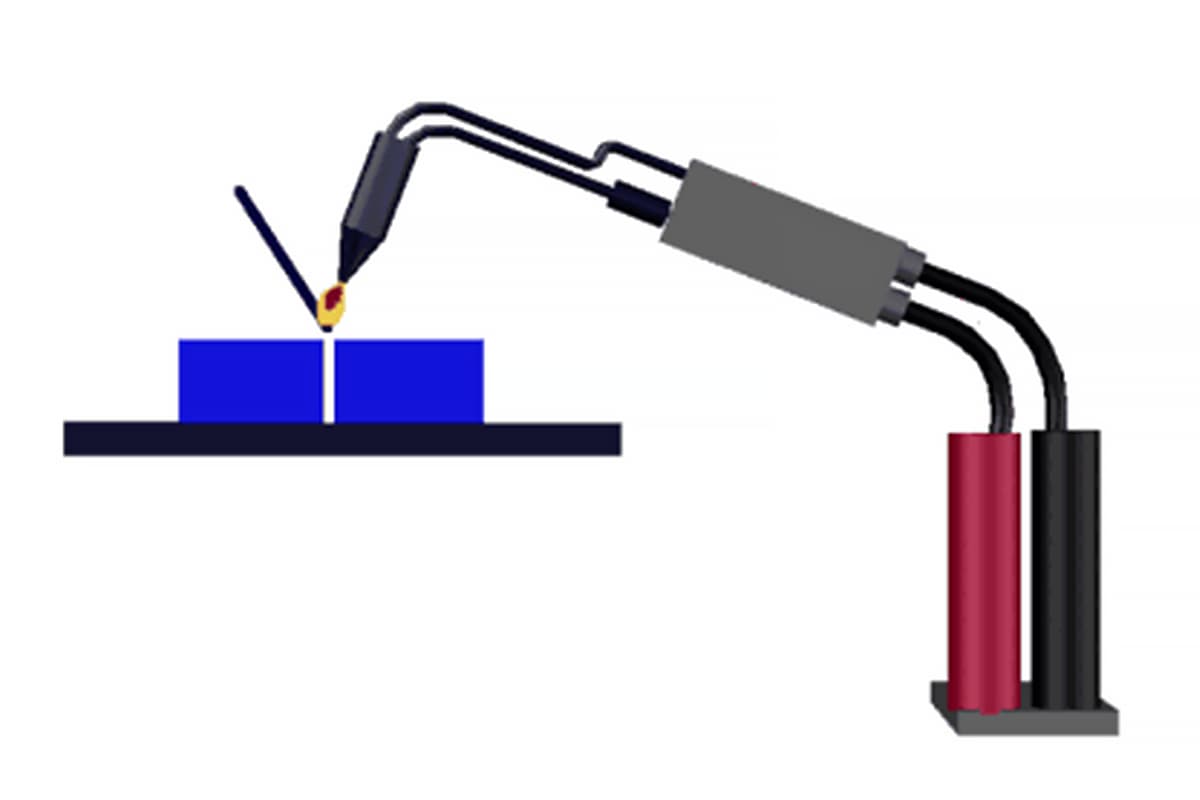
In addition to its application in CNC machine tools, computer-aided manufacturing is also widely used in the control of various other devices, such as presses, flame or plasma arc cutting, laser beam machining, automatic plotters, welding machines, assembly machines, inspection machines, automatic looms, computer embroidery, and garment cutting.
2. Application of Computer-Aided Design and Manufacturing Technology in Sheet Metal Parts
The use of computer-aided design and manufacturing technology in the design and production of sheet metal products and components significantly transforms the conventional methods of production companies for designing and manufacturing sheet metal parts, even impacting their management and competitive strength.
Therefore, any enterprise dealing with the production of sheet metal products and components must strive to research, develop, or use computer-aided design and manufacturing technologies to maintain their developmental advantage. Sheet metal parts are characterized by their light weight, high strength, conductivity (suitable for electromagnetic shielding), low cost, and excellent mass production capabilities.
Currently, they are widely used in fields such as electronics, communications, automotive industry, and medical equipment. For instance, sheet metal parts are essential components in computer cases, cell phones, and enclosures for power products.
With the increasingly widespread application of sheet metal parts, their design has become a crucial aspect of the product development process. This requires development designers to be proficient in the techniques of computer-aided design and manufacturing of sheet metal parts, ensuring that the designed parts meet the functional and aesthetic requirements of the product while also simplifying die manufacturing and reducing costs.
The process of computer-aided design and manufacturing of sheet metal parts starts with computer-aided design, goes through numerical simulation unfolding, nesting, cutting, stamping, bending, and other procedures, and ends with the computer automatically outputting the part’s process route, operation content, tooling motion trajectory (tool position file), and numerical control program.
The most important aspects are the calculation of the blank unfolding dimensions of sheet metal parts, graphic drawing, and the preparation of numerical control programs. The computer evaluates the individual features of the sheet metal parts and the relationships between them from mathematical analysis and manufacturing (sheet metal process parameters) perspectives, providing instant feedback to product designers for modifying any unreasonable structural designs.
2.1 Computer-Aided Sheet Metal Part Design and Unfolding
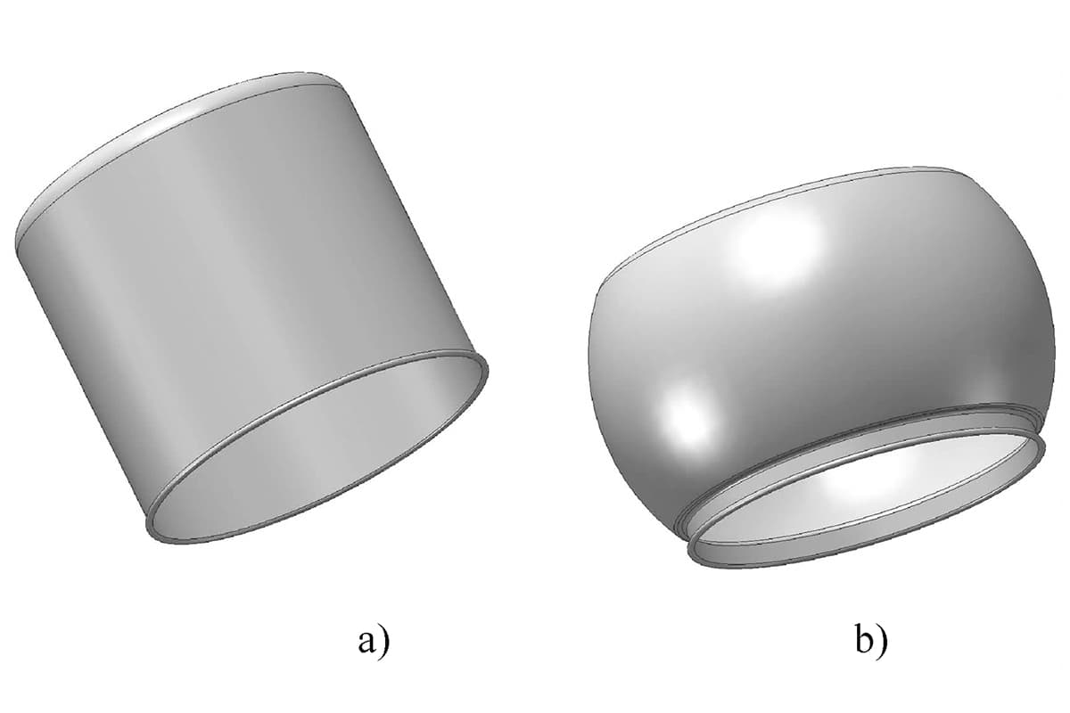
Sheet metal parts can generally be divided into three categories: flat parts (i.e., general flat stamping parts), bending parts (i.e., parts formed by sheet bending or bending processing), and forming parts (i.e., parts made by drawing and other forming methods, either regular or free-form surface parts). Sheet metal parts differ significantly from parts produced by common machining methods.
Among many processes in stamping sheet metal parts, bending deformation (press bending process) is the main method of creating complex spatial relationships. The design and unfolding of various regular or complex shaped sheet metal parts can be divided into two methods based on models and styling.
Traditional sheet metal cutting methods include drafting and calculation methods. Basic methods of drafting include parallel line, radiant line, and triangle line methods; calculation methods replace the laying out and drafting process in drafting methods, calculating the coordinates and line lengths of feature points in the unfolded drawing, and then drawing the calculated results.
Using a computer to complete these calculations is the most basic model-based sheet metal CAD method. For frequently used box-type, vertical shaft, door panel and other types of sheet metal parts, the design unfolding method based on the model requires a certain amount of work to build the model, but it is very reliable and efficient when used.
There are two geometric modeling methods for sheet metal parts: 2D sheet metal geometric modeling and 3D sheet metal geometric modeling. The former includes coding methods, facet assembly methods, and interactive size input methods; the latter includes bending transformation assembly methods, voxel assembly methods, etc.
The common drawback of these methods is that when the definition is incorrect, modifications are very cumbersome and may even require re-input to build the model. The most effective way to overcome these shortcomings is to use feature modeling techniques, such as SolidWorks, Pro/E, UG, CATIA, etc., which are design platforms that use feature modeling to build sheet metal product models.
The modeling functions and methods of various CAD/CAM systems are different. Simple modeling methods only use regular surfaces and solid modeling, while complex modeling methods have advanced surface modeling and solid modeling functions, such as part design applications that provide functions like scanning, deep drawing, ribbing, spiral, cutting, etc., and sheet metal design can automatically generate bending process holes, automatic unfolding, and simulation.
1. Assembly Modeling Operation Method
Using basic solid geometric elements such as thin sheet cubes and hollow cylinders, gradually combined to grow into the geometric model of the part, is the basic method of sheet metal modeling. The elements used in the assembly modeling method can be thickness-less surface elements or thick volume elements.
Many sheet metal parts are made of equal-thickness plates, which allows the use of thickness-less surface blocks in the modeling process to construct the basic structure of the sheet metal part and then specify the direction to grow out the thickness of the part. This method of first designing a thickness-less structural frame and then growing a thick part is also applicable to complex sheet metal parts such as overlays.
2. Methodology of Feature Modeling
A feature is a collection of product description information, not only presenting a specific shape formed according to certain topological relationships, but also reflecting specific engineering semantics, suitable for use in design, analysis, and manufacturing.
Features can be categorized into shape features, precision features, and material features. Among these, shape feature is key, serving as the carrier or base for other features and the core for implementing parametric feature modeling. It can define geometric bodies or entities with certain engineering significance.
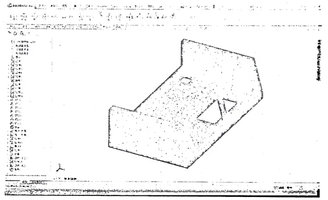
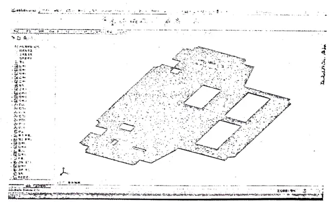
Sheet metal parts can be decomposed into one or more shape features. From the perspective of feature modeling, a sheet metal part comprises a series of features, and their interconnections form a complete component. An example of feature modeling of a sheet metal box is shown in Figure 10-1.
Based on the characteristics of sheet metal parts, the following main features can be summarized:
1) Planar features, which refer to the planar shape that makes up the component, are the basic parts of the component, the linking section of the bending parts, and the parent body for local forming and punching.
2) Bending features, which are shapes produced by bending processes. The simplest bending feature is represented by a cylindrical bending area.
3) Hole features, which act as general sub-features and attach to other features, such as punching on a plane or bending feature.
4) Local forming features, which are shapes produced by local forming processes on stampings, usually have fixed shape and feature parameter types, but the numerical values change, hence can be expressed by parameters.
3. Methodology of Unfolding
The basic principle of the sheet metal unfolding method is to record the topological relationships between each face block and its connected face blocks during the design process and use this as the basis for unfolding.
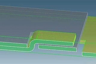
Simpler systems can first specify a reference plane, then each face to be unfolded, and step by step unfold the entire sheet metal part. Advanced CAD/CAM systems can unfold multiple surfaces in one operation. The unfolded diagram of the box in Figure 10-1 is shown in Figure 10-2.
Figure 10-1: Feature Modeling Diagram of a Specific Sheet Metal Enclosure
Figure 10-2: Unfolded View of the Enclosure from Figure 10-1
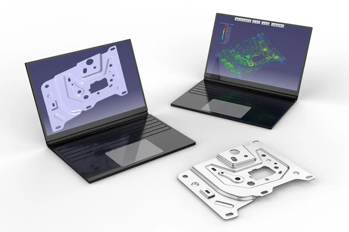
2.2 Computer-Aided Material Layout
The cost of producing sheet metal parts mainly includes material costs, design fees, and mold fees, with material costs accounting for a significant portion. Using a computer-aided layout system is an essential way to reduce material costs.
The optimization of the objective function method is a widely applied method for sheet metal layout. Its underlying principle is to use the parameters Δx (translational shift in the X direction), Δy (translational shift in the Y direction), and Δφ (rotation) during the replication of similar workpiece blocks as variables, and then construct a specific objective function based on the types of workpiece blocks participating in the layout, the shape and quantity of the corridors.
Iterations are performed based on a certain algorithm around the objective function, and when the objective function reaches a preset precision goal, the iteration stops, and the layout is performed based on the parameters at the time the iteration stops. To improve efficiency, the range of some parameter changes can be fixed.
When a variety of workpiece block types participate in the layout, and there are no restrictions on the Δx, Δy, and Δφ parameters for duplicating various workpiece blocks, the layout effect will greatly reduce.
At this time, some preparatory work can be done for the layout, such as judging the geometric properties of the workpiece blocks participating in the layout, or tolerating the workpiece blocks during the search for Δx, Δy, and Δφ, and using simple and fewer closed-loop contours to replace the original workpiece block contours.
Different layout systems (software) have different basic functions and operation modes, but the basic content includes:
1. Selecting sheet material: Choose the sheet material for the layout from the material library, including standard specifications and leftover material from previous use.
2. Specifying workpiece blocks: Specify the type and number of workpiece blocks to be duplicated from the workpiece block library established after the sheet metal parts are expanded.
3. Optimizing layout: Layout the specified workpiece blocks and their quantities on the selected sheet material. This menu level allows for selection of sub-items such as single row, head-to-head double row, mixed nesting, interactive layout, etc.
4. Layout editing: Preprocess the workpiece blocks participating in the layout or check the layout results for interference, manually adjust if necessary, and re-layout if needed.
5. Output of layout results: Output the layout result diagram and corresponding data files (including tool positions), material utilization rate, and a cutting plan report.
2.3 Numerical Control Instruction Compilation
Numerical control programming is currently one of the most beneficial aspects of the CAD/CAM system, playing a crucial role in achieving design and manufacturing automation, improving machining accuracy and quality, and shortening product development cycles.
Numerical control programming is the entire process of going from part drawings to obtaining numerical control machining programs. Its main tasks are to calculate machining cutter points (also known as CL points), determine the cutter path sequence, determine process parameters, and other process route designs, compile numerical control instruction files according to the specific format of the numerical control system, and control the motion content of the numerical control instruction files.
In the CAD/CAM of complex sheet metal parts, process design work is often very complicated and can be completed by a specialized CAP four system. The machining object of sheet metal cutting is flat sheet material, usually using cutting, shearing, and punching methods. The process design work is relatively simple and can be included in the numerical control programming system.
Among cutting, shearing, and punching, the numerical control punching instruction file is the most complex. The following will introduce numerical control programming for sheet metal expansion blanking based on numerical control punching.
1. Input of design information in numerical control punching instruction compilation: Sheet metal design, expansion, and layout can provide output such as graphics and data files, with dimensions marked on the graphics. The simplest method of compiling numerical control instructions is manual compilation, where humans read and analyze graphics and data.
Sheet metal expansion blanking generally only involves the processing of plane graphic information. Using the numerical control tool trajectory generation method based on points and lines, programming operations can be performed directly on the graphics in a visual way. Use the cursor to specify the graphic element closest to the cursor position, and the computer confirms the geometric information of this graphic element.
2. Process design in numerical control punching instruction compilation: The basic content of process design during numerical control punching mainly includes: selecting punches, determining the punching order of each graphic element, determining the step distance and sheet movement speed during step-by-step punching, setting the position of the claw, etc.
The same shape and size contours may use different punching methods due to the operator’s habits and technical level. For example, when punching large holes and slots, smaller punches can be used to punch out the contours of the holes and slots, then move the punch away, pause the machine, manually remove the remaining material in the hole, and then continue processing.
Alternatively, a larger punch can be used to punch out not only the contours of the holes and slots but also all the internal material into fragments. This choice can be handled by selecting different menu branches during the programming process. In more functional CAD systems, there can be two instruction methods: fragment punching and non-fragment punching.
3. Programming of Numerical Control Punching Instructions
Computer-aided programming is the process of using a computer to complete tasks related to programming that were originally done manually. In the process of writing instructions for sheet metal punching, the most basic operation is to specify the punch (tool) and the elements to be programmed, after which the programming system can automatically generate numerical control instruction files.
For more advanced instruction systems, programming operations also include whether to use grouped punching instructions, whether to call sub-programs, etc.
4. Optimization and Simulation of Numerical Control Punching Instructions
After the numerical control punching instruction file is generated, it requires post-processing, and the basic post-processing operations are optimization and simulation.
1) The optimization of punching instructions generally includes punch optimization and trajectory optimization.
The purpose of punch optimization is, on the one hand, to gather together the punching instructions completed by the same punch to reduce mold changes during processing. On the other hand, it is to arrange the punching order according to different types of punches, usually with smaller punches first and larger ones later. Trajectory optimization is mainly to reduce the length of the idle stroke during punching.
2) The simulation function can generally display the execution process of the punching instruction file, check whether the punching instruction is reasonable, and whether there may be interference with the gripper during the punch movement.
It can also reverse the punching instruction file into a graphic, and compare it with the graphic before programming, analyze the consistency of the two graphics, and thus judge the correctness of the punching instruction file.
As the founder of MachineMFG, I have dedicated over a decade of my career to the metalworking industry. My extensive experience has allowed me to become an expert in the fields of sheet metal fabrication, machining, mechanical engineering, and machine tools for metals. I am constantly thinking, reading, and writing about these subjects, constantly striving to stay at the forefront of my field. Let my knowledge and expertise be an asset to your business.
Have you ever wondered how metal can be shaped into intricate forms with precision and efficiency? This article dives into the fascinating world of metal expansion methods, explaining various techniques…
Have you ever wondered how sheet metal parts are joined together to create complex structures? In this blog post, we'll explore the fascinating world of sheet metal joining techniques. As…
How do you ensure the reliability of sheet metal connections in your projects? Understanding the various methods of threaded connections and riveting is essential. This article delves into the principles…
Have you ever wondered how everyday objects stay together? From the plastic toys we play with to the sturdy metal bridges we cross, joining techniques are at work. In this…
In this blog post, we'll dive into the intriguing terminology and techniques used in this essential manufacturing field. Our expert mechanical engineer will guide you through the key concepts, providing…
1. Cold Bending Forming Technology Cold bending forming technology is a continuous localized cold processing method, which involves applying external force to the metal at the bend angle through multiple…
Imagine a production line that not only boosts efficiency but also slashes costs and enhances safety. The automated steel door frame production line achieves just that by integrating advanced robotics…
Why is straightening parts in sheet metal fabrication so crucial? Imagine a car with wobbly wheels. Similarly, uneven metal parts can lead to inefficiencies and defects in production. This article…
How can the sheet metal fabrication industry stay ahead of rising labor costs and production challenges? Enter the Flexible Manufacturing System (FMS). This article explores how FMS integrates automated technologies…